Key Takeaways
- Definition: Slope stability is the evaluation of whether resisting shear strength along a potential slip surface is large enough to overcome the forces driving the soil or rock mass downhill.
- Main use case: Engineers apply slope stability to cuts, fills, embankments, levees, earth dams, natural hillsides, and sites where grading or nearby loading can trigger movement.
- What usually controls: Geometry, groundwater, shear strength assumptions, weak layers, and staged construction often matter more than any single equation.
- What you should leave with: You should understand the factor of safety concept, the typical workflow, the common failure modes, and why drainage is often the fastest path to a more stable slope.
Table of Contents
Introduction
Direct answer: Slope stability is the geotechnical check used to determine whether soil or rock on an incline will remain in place or slide along a likely failure surface. Engineers compare driving forces to resisting shear strength, then adjust geometry, drainage, reinforcement, or loading until the slope meets an acceptable factor of safety.
This page is for engineering students, FE/PE exam candidates, and practicing engineers who need a clear, practical understanding of how slope stability works in design. The goal is not just to define the topic, but to show how engineers think through real slopes: what data they need, what usually controls performance, where simplified methods are useful, and where judgment matters more than a neat textbook answer.
Slope Stability infographic
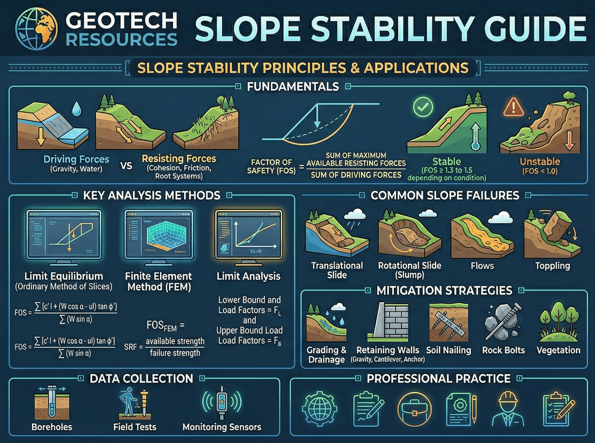
Start by noticing how water, geometry, and the location of the slip surface interact. A steeper slope, a higher groundwater table, or a weak layer passing through the critical zone can all reduce stability dramatically even when the soil type itself has not changed.
What is slope stability?
Slope stability is the branch of geotechnical engineering that asks a straightforward but high-stakes question: will this sloping ground stay in place, or will it move? The answer depends on whether the material along a possible failure surface has enough shear resistance to overcome the forces trying to drive it downhill. In design terms, that means engineers compare resisting and driving actions and express the result as a factor of safety.
The topic applies to far more than dramatic landslides. It matters in routine highway cuts, building pads near descending terrain, retaining wall backslopes, landfill side slopes, embankments, levees, and excavations. A slope can also “fail” without a sudden collapse. Progressive cracking, excessive deformation, localized sloughing, and long-term creep can all be unacceptable even if the slope has not yet experienced a large slide.
A useful mental model is this: slope stability is not a soil classification problem alone, and it is not only a geometry problem. It is an interaction problem. The behavior comes from how soil strength, stress level, pore pressure, stratigraphy, and construction history combine at the same time.
Core principles, variables, and units
Most slope stability work is built around shear strength, effective stress, pore pressure, and geometry. In many projects, the soil does not fail because the total weight is suddenly larger than expected. It fails because water pressure rises, effective stress falls, and the available shear resistance along part of the slope drops below what the geometry demands.
Key variables and typical ranges
The exact values depend on site conditions and whether the analysis is drained, undrained, static, or seismic. Still, engineers should have a feel for the core quantities and what they mean physically before trusting any software output.
- FS Factor of safety, dimensionless; the ratio of resisting to driving effects along a potential failure surface.
- c′ Effective cohesion intercept, usually in kPa or psf; often small for clean sands and highly interpretation-sensitive for many soils.
- ϕ′ Effective friction angle, in degrees; a major control on drained slope behavior, especially in granular soils and compacted fills.
- su Undrained shear strength, usually in kPa or psf; commonly used for short-term stability in saturated clays.
- u Pore water pressure, in kPa or psf; rising pore pressure reduces effective stress and can sharply reduce stability.
- γ Unit weight, commonly kN/m³ or pcf; changes with material type, moisture condition, and compaction.
- β Slope angle, usually in degrees from horizontal; steeper slopes generally require stronger materials, better drainage, or reinforcement.
Before refining material parameters, first ask whether the slope geometry and groundwater assumptions make sense. An elegant analysis with the wrong water table is usually less useful than a simple analysis with the right drainage picture.
Decision logic and design workflow
A good slope stability workflow starts with the ground model, not the software. Engineers first define the slope geometry, stratigraphy, groundwater conditions, loading, and likely failure mechanisms. Only after that do they choose the analysis method and strength assumptions.
1) Define the slope type: natural slope, cut, fill, embankment, dam, levee, or temporary excavation.
2) Build the ground model: layers, weak seams, groundwater, seepage direction, and staged loading.
3) Select strength assumptions: drained effective parameters, undrained strength, or both depending on timing.
4) Screen likely failure modes: shallow translational, circular, composite, toe failure, base failure, or rock-controlled modes.
5) Run stability checks for the critical cases: end of construction, steady seepage, rapid drawdown, surcharge, and seismic where applicable.
6) If the factor of safety is inadequate, improve drainage, flatten the slope, reduce load, reinforce the mass, stabilize the toe, or improve the ground.
7) Re-check constructability, maintenance, and whether the design assumptions can actually be achieved in the field.
This workflow matters because slope stability is highly case-dependent. The “right” method is the one that captures the governing condition, not the one with the most inputs.
Equations and calculations
The main equation readers should remember is the factor of safety concept. The exact formulation depends on the chosen method, but the core idea does not change.
In limit-equilibrium analysis, the slope is treated as a potential sliding mass, and the engineer evaluates whether the available strength along the failure surface is enough to resist movement. Many methods are used in practice, including ordinary method of slices, Bishop simplified, Janbu, Spencer, and Morgenstern-Price. For many introductory and routine problems, the difference between them is less important than having the right geometry, pore pressure distribution, and material model.
Mohr-Coulomb strength in slope stability
When effective stress parameters are used, the available shear strength is often described by the Mohr-Coulomb relation:
Here, \( \tau_f \) is the shear strength at failure, \( c’ \) is the effective cohesion intercept, \( \sigma’ \) is the effective normal stress on the potential failure surface, and \( \phi’ \) is the effective friction angle. The key practical point is that \( \sigma’ \) depends on pore pressure. When pore pressure rises, effective stress falls, and so does the available shear resistance.
Practical units and sanity checks
Keep units consistent. In SI work, shear strength and pore pressure are commonly tracked in kPa, geometry in meters, and unit weight in kN/m³. In US customary work, strength and pressure may be in psf or ksi depending on context, geometry in feet, and unit weight in pcf. A surprisingly common mistake is mixing lab values, report values, and software defaults without confirming they all live in the same unit system.
Worked example
Example: conceptual check for a compacted fill slope
Suppose a project includes a 7 m high compacted fill slope at 2.5H:1V supporting a roadway shoulder. The fill is a sandy silt over a softer native layer, and seasonal groundwater can perch near the interface after heavy rain. The first-pass static analysis using drained parameters shows a factor of safety of about 1.38. On paper that may look acceptable for some routine cases, but the section deserves more scrutiny because the perched water condition is not steady year-round and the weaker interface can localize the failure surface.
The engineer then evaluates a wet-season condition with elevated pore pressure along the interface and finds the factor of safety drops to about 1.17. That result changes the design conversation completely. Instead of relying on the dry-condition check, the team may flatten the slope, add chimney and toe drainage, improve compaction control near the face, and move any surcharge farther back from the crest. In many real projects, drainage and load management provide the needed improvement faster and more economically than jumping directly to structural reinforcement.
The takeaway is that the critical case is often not the “average” condition. It is the short period when water, loading, and geometry align in the least favorable way.
Engineering judgment and field reality
Field conditions rarely match the neat profile implied by a single cross-section. Slopes often contain variable fill, desiccation cracks, root channels, loose pockets, buried topsoil, old slide debris, or seams that are hard to map with limited exploration. This is why experienced engineers spend so much time on reconnaissance, aerial imagery, construction history, drainage patterns, and evidence of past movement.
Water deserves special emphasis. In slope work, drainage is not a detail added near the end of design. It is often one of the main design variables. Surface runoff can infiltrate from the crest, seepage can daylight on the face, and toe erosion can remove support from below. A slope that performs acceptably in dry months may become marginal after prolonged rainfall or rapid reservoir drawdown.
Construction sequence also matters. A cut slope may be stable long term but unsafe during excavation before drainage measures are installed. A fill slope may look adequate in the final geometry but become vulnerable if compaction near the face is poor or if the fill is placed faster than pore pressures can dissipate in soft foundation soils.
The most common reason slope analyses miss the real problem is not the math. It is an incomplete site model that underestimates water, weak layers, or construction-stage conditions.
Where this method breaks down
Simplified slope stability methods are powerful, but they are not universal. They become less reliable when the material behavior is strongly three-dimensional, when deformations control more than collapse, when cracking changes the water path, or when reinforcement, creep, or strain-softening govern the response. Very heterogeneous slopes, anisotropic strength conditions, and rock slopes controlled by joint sets may require more specialized modeling or a completely different framework.
Limit-equilibrium methods are especially vulnerable to bad pore pressure assumptions. They can give a very polished result while still missing the critical condition if the groundwater model is oversimplified. The same caution applies when a single undrained strength value is used across a clay profile that actually changes significantly with depth or stress history.
Another breakdown point occurs when users treat the computed critical surface as a physical certainty. It is better viewed as the most critical surface within the assumptions and search limits that were supplied. If the search space, geology, or loading cases are incomplete, the “critical” result may not be critical at all.
Common pitfalls and engineering checks
- Using drained strength parameters for a short-term saturated clay problem where undrained behavior governs.
- Ignoring perched water, seepage exit points, or seasonal groundwater rise.
- Checking only the final slope and skipping end-of-construction or rapid drawdown cases.
- Assuming compaction quality and drainage details will be perfect without tying them to construction QA/QC.
- Placing surcharges, buildings, or traffic too close to the crest without rechecking global stability.
- Focusing only on factor of safety and not watching for serviceability issues like cracking, erosion, or progressive movement.
A dangerous mistake is to “fix” a slope by adding strength assumptions instead of fixing the water problem that is actually causing the instability.
Ask what controls the slope if the water table rises, if the toe erodes, if the crest gets loaded later, and if the as-built geometry differs slightly from the design section. Those quick questions often reveal whether the design is robust or fragile.
| Issue | Main signal | Why it matters | Typical response |
|---|---|---|---|
| High pore pressure | Wet zones, seepage, softening, movement after storms | Reduces effective stress and available shear strength | Improve surface and subsurface drainage, review seepage assumptions |
| Weak layer or interface | Movement concentrated at one elevation | Can create a low-strength slip path | Refine investigation, flatten slope, stabilize or remove the weak zone |
| Crest surcharge | New load near top of slope | Increases driving forces and can shift the critical surface | Set back the load, reduce weight, or reinforce the slope |
| Toe erosion or excavation | Loss of support at the base | Can trigger rotational or translational failure | Protect the toe, revise geometry, evaluate staging carefully |
How engineers visualize slope behavior
A helpful way to picture slope stability is to imagine several possible failure surfaces being tested through the soil mass rather than just one obvious slip line. The critical surface is the one that produces the lowest acceptable factor of safety under the assumed conditions. In a homogeneous embankment that may look roughly circular, but in layered soils it often bends to follow weaker strata, interfaces, or seepage-controlled zones.
Engineers also visualize where the water goes. Surface runoff, ditch flow, infiltration from the crest, and pore pressure at the toe all affect the shape of the real problem. That is why a cross-section with groundwater and drainage details is often more useful than a beautifully rendered soil-only sketch.
This section stays text-only because the main infographic already covers the core visual concept and does not need duplication.
Relevant standards and design references
Slope stability design usually sits at the intersection of geotechnical manuals, transportation guidance, dam or levee criteria, and project-specific risk requirements. The exact reference set depends on the project type, but these are the kinds of documents engineers routinely lean on:
- FHWA geotechnical manuals: Commonly used for highway embankments, cuts, reinforced soil slopes, and landslide mitigation workflows.
- USACE engineering manuals: Especially important for levees, dams, seepage-sensitive earth structures, and staged loading problems where water is central to performance.
- AASHTO transportation guidance: Relevant when slope decisions affect roadway embankments, retaining systems, drainage coordination, and infrastructure safety factors.
- Local DOT or agency geotechnical manuals: These often control acceptable target factors of safety, drainage details, and required investigation depth more directly than a general textbook.
- Project-specific geotechnical reports and construction specifications: These are the real source of truth for the site because they define subsurface assumptions, material properties, and the field QA/QC requirements that the design depends on.
Frequently asked questions
The factor of safety is the ratio of resisting shear strength to the forces or stresses driving the slope toward movement along a potential failure surface. A value above the required target suggests acceptable stability for the assumed geometry, groundwater, and loading case, but it is only as reliable as the site model behind it.
The most common causes are rising pore pressure, toe erosion, surcharge loading near the crest, construction-stage changes, and weak layers that were missed or underestimated during investigation. In many real slopes, water is the key trigger because it lowers effective stress and changes seepage forces at the same time.
Slope stability is the analysis and design check used to evaluate whether failure is likely, while landslide mitigation is the set of actions used to reduce that risk once the governing mechanism is understood. In practice, the analysis should explain whether the best fix is drainage, flattening, reinforcement, toe support, or some combination.
No. Circular surfaces are common for homogeneous soil slopes and introductory analyses, but many real failures are translational, composite, wedge-shaped, or controlled by weak seams, rock discontinuities, or reinforcement geometry. The assumed surface must match the material behavior and site geology.
It shows up in highway cuts, embankments, retaining wall backslopes, building sites near descending terrain, landfill side slopes, levees, dams, and temporary excavations. Any project that changes grade, drainage, or loading near sloping ground can become a slope stability problem whether or not it is called one at the start.
Summary and next steps
Slope stability is the discipline of checking whether a sloping mass of soil or rock has enough resistance to remain in place under the conditions that actually matter: geometry, water, loading, material strength, and construction sequence. The factor of safety is the familiar summary metric, but the real engineering value comes from understanding what controls that number and how it can change over time.
The strongest slope designs are usually the ones built on a defensible ground model and a realistic water model. In practice, drainage, slope shaping, toe support, staged construction, and reinforcement all have their place, but they only work well when they are matched to the real failure mechanism. That is why slope stability is as much about field judgment and investigation quality as it is about analysis.
Where to go next
Continue your geotechnical learning path with these closely connected topics.
-
Study Soil Mechanics
Build the strength, effective stress, seepage, and shear concepts that sit underneath every slope analysis.
-
Read Landslide Mitigation next
Extend this topic into practical stabilization strategies such as drainage, grading changes, toe support, and reinforcement.
-
Compare with Retaining Wall Design
Useful when slope geometry, earth pressure, and global stability start overlapping with wall selection and detailing.