Key Takeaways
- Core idea: A water distribution system delivers treated water from storage or treatment facilities to customers through a controlled network of pipes, pumps, tanks, valves, hydrants, and service connections.
- Engineering use: Engineers use distribution system planning to maintain service pressure, meet peak demand, support fire flow, protect water quality, and keep the network maintainable.
- What controls it: Pipe size, demand, elevation, storage level, pump head, pressure zones, valve status, and pipe roughness all affect how water moves through the system.
- Practical check: A system can meet normal demand and still perform poorly if it has dead ends, excessive water age, weak valve isolation, poor pressure control, or inadequate fire-flow capacity.
Table of Contents
Introduction
A water distribution system is the network of pipes, pumps, storage tanks, valves, hydrants, meters, and service lines that delivers treated water from a source or treatment plant to customers. Engineers design these systems to maintain pressure, provide enough flow for normal and fire demand, preserve water quality, and keep service reliable during maintenance or emergencies.
How a Water Distribution System Works
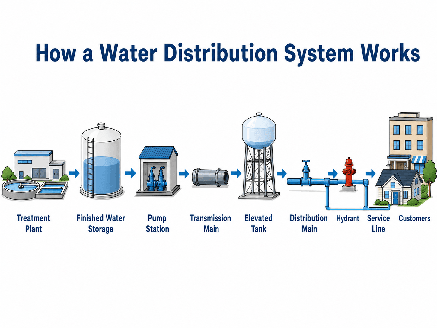
Notice that the system is not just a pipe network. Storage, pumping, elevation, and control devices all work together to keep water available at usable pressure as demand changes.
What Is a Water Distribution System?
A water distribution system is the delivery side of a potable water supply network. After water is treated or otherwise made suitable for its intended use, the distribution system carries it through mains, valves, pumps, tanks, hydrants, meters, and service connections to the points where people actually use it.
In water resources engineering, the distribution system sits between water treatment and water use. It has to do more than move a volume of water from one location to another. It must deliver the right amount of water at the right pressure, preserve water quality, remain serviceable during repairs, and provide redundancy when a pipe, pump, or valve is out of service.
The basic question is not only “Can water reach the customer?” A better engineering question is “Can the system meet normal demand, peak demand, fire-flow demand, pressure limits, water quality goals, and maintenance needs at the same time?”
Water Distribution System Components
Water distribution system components work together to deliver flow, maintain pressure, isolate repairs, support fire protection, and protect water quality. The network only performs well when those components are sized, located, operated, and maintained as a system.
| Component | Primary function | What engineers check |
|---|---|---|
| Finished water storage | Stores treated water before or within the distribution network. | Storage volume, turnover, water age, tank mixing, emergency reserve, and level control. |
| Pump station | Adds energy to move water through the system or into a higher pressure zone. | Pump head, flow capacity, redundancy, power reliability, controls, and surge risk. |
| Transmission main | Moves larger volumes between major facilities, storage tanks, or pressure zones. | Pipe diameter, head loss, material, isolation valves, and criticality if the main fails. |
| Distribution main | Moves water through neighborhoods, streets, campuses, or service districts. | Looping, dead ends, fire flow, residual pressure, pipe age, and available maintenance access. |
| Elevated or ground storage tank | Provides balancing storage, emergency supply, and pressure support. | Hydraulic grade, operating range, fill/drain cycling, mixing, inspection access, and overflow routing. |
| Valves and pressure control devices | Control flow direction, isolate repairs, reduce pressure, or separate pressure zones. | Valve spacing, accessibility, pressure settings, maintenance history, and whether closure creates dead zones. |
| Hydrants | Support fire protection, flushing, and field testing. | Hydrant spacing, available flow, residual pressure, valve isolation, and accessibility. |
| Service lines and meters | Connect the distribution main to individual users. | Service material, meter sizing, backflow risk, pressure, leakage, and customer-side demand patterns. |
Types of Water Distribution Systems
The phrase “types of water distribution systems” can refer to either the network layout or the way pressure is created. Both meanings matter. A municipal water distribution system may use a grid or looped pipe layout while also relying on a combination of gravity storage, pumps, and pressure control valves.
Gravity, pumped, and combined systems
A gravity distribution system uses elevation difference and storage height to provide pressure. A pumped distribution system relies more heavily on mechanical energy from pumps. Most real systems are combined systems, using pumps to move water into tanks or pressure zones and then using storage elevation to help provide service pressure.
Branched, grid, looped, and radial systems
Pipe layouts describe how mains are connected. Branched systems are simple but have dead ends. Grid and looped systems provide multiple flow paths and better redundancy. Radial systems distribute water outward from a central source or storage point and are often discussed in conceptual planning or older educational classifications.
| System type | How it works | Best use or concern |
|---|---|---|
| Gravity system | Uses elevated storage or source elevation to create pressure. | Efficient when terrain and storage location support reliable service pressure. |
| Pumped system | Uses pumps to create the pressure needed to serve customers. | Useful where elevation does not provide enough head, but power and pump redundancy become critical. |
| Combined system | Uses pumps, tanks, valves, and pressure zones together. | Common in real utilities because demand, terrain, and growth rarely fit one simple method. |
| Branched system | Water moves along a main line and into dead-end branches. | Simple and lower cost, but weaker for redundancy and water age control. |
| Grid or looped system | Mains are interconnected so water can reach a point from multiple directions. | Better for reliability, fire flow, and maintenance flexibility. |
| Radial system | Water is supplied outward from a central source or storage point. | Useful as a planning concept, but real systems often evolve into hybrids. |
Water Distribution System Layouts
Water distribution system layout controls redundancy, water age, fire-flow reliability, and how much of the network must be shut down during repairs. In practice, many systems are hybrids because cities expand in phases, older mains remain in service, and terrain forces pressure-zone boundaries.
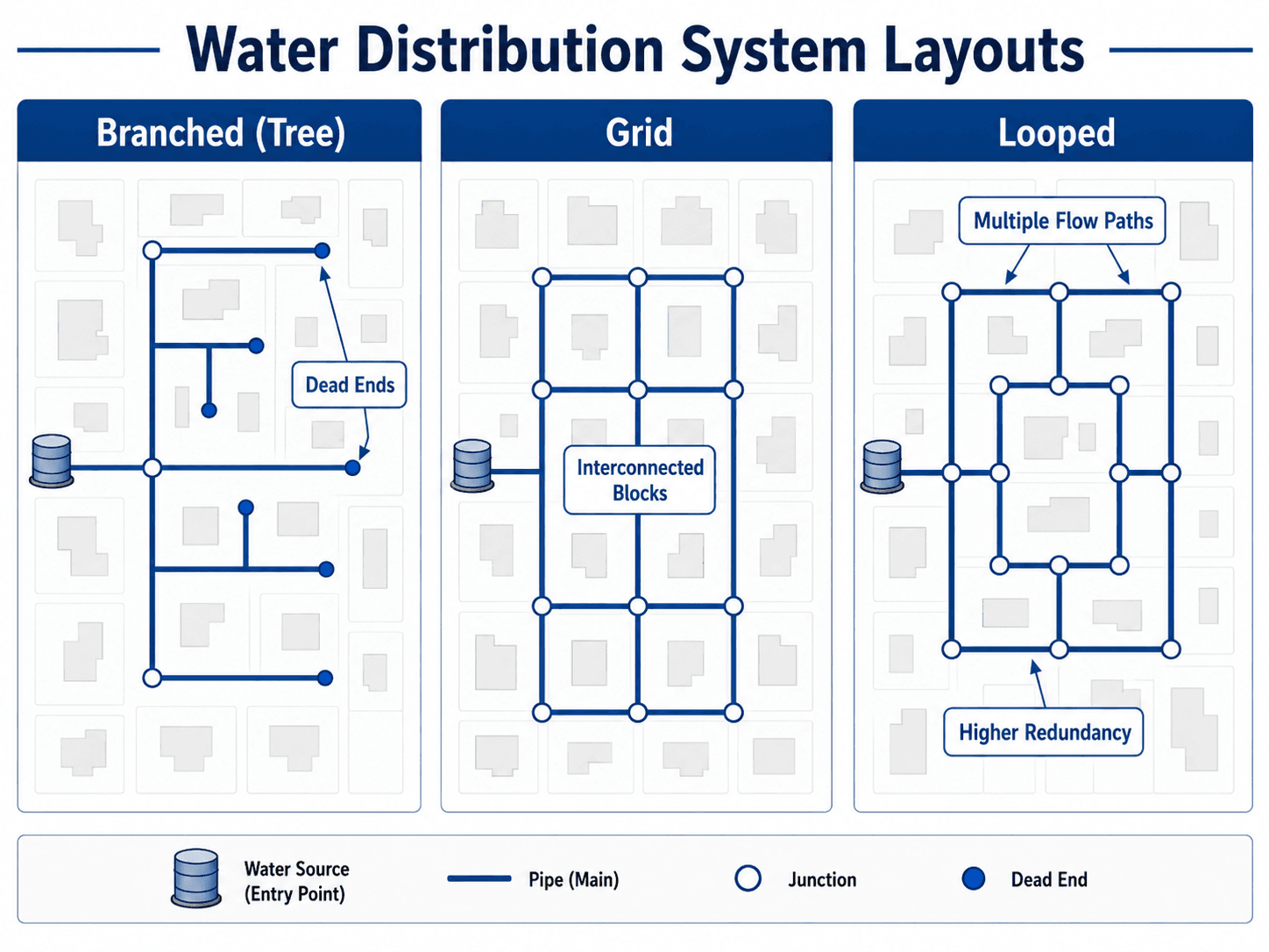
| Layout type | Where it is commonly seen | Strength | Common concern |
|---|---|---|---|
| Branched or tree layout | Small systems, rural extensions, older developments, and cul-de-sacs. | Simple to construct and easy to understand hydraulically. | Dead ends can increase water age, reduce redundancy, and require more flushing. |
| Grid layout | Urban street networks and planned developments. | Interconnected blocks allow more than one path for water movement. | Hydraulic behavior depends on valve status, demand distribution, and pipe condition. |
| Looped layout | Critical service areas, fire-flow corridors, campuses, and commercial districts. | Better redundancy and more reliable flow during maintenance or high demand. | Higher installation cost and more complex valve management. |
Transmission Mains, Distribution Mains, and Service Lines
A water system contains several pipe categories that are easy to confuse. The difference is not only pipe size; it is also the pipe’s role in the system. Transmission mains move water between major facilities, distribution mains serve neighborhoods and hydrants, and service lines connect individual users.
| Pipe category | Main role | Typical engineering concern |
|---|---|---|
| Transmission main | Moves large volumes between a treatment plant, storage tank, pump station, or pressure zone. | Criticality, large head loss impact, isolation options, surge, and service disruption if the main fails. |
| Distribution main | Moves water through streets, neighborhoods, campuses, or service districts. | Looping, fire flow, residual pressure, dead ends, pipe age, and valve spacing. |
| Service line | Connects the distribution main to a customer meter, building, or property connection. | Material, meter size, backflow control, leakage, pressure, and customer-side demand. |
A transmission main failure can affect an entire pressure zone or storage facility. A service line issue usually affects one customer or property. Distribution mains sit between those extremes and are often the focus of fire-flow, looping, and neighborhood pressure checks.
Pressure, Flow, Storage, and Pressure Zones
Water distribution systems are pressurized networks. Pressure comes from elevation, storage level, pump energy, and the hydraulic grade line. As water flows through pipes, friction losses reduce available pressure, especially during peak demand or fire-flow conditions.
In practical distribution work, engineers think in terms of tank water level, ground elevation, pump head, pipe losses, and residual pressure at the service point. A customer at a higher elevation needs more hydraulic grade to receive the same service pressure as a customer at a lower elevation.
Why storage tanks matter
Storage tanks help balance the difference between supply and demand. When demand is low, the system can refill storage. When demand rises, stored water can help maintain service. Elevated tanks also provide gravity pressure, which is why tank water level and ground elevation are so important.
Why pumps matter
Pumps add head to the system. They may move water out of a treatment facility, fill a tank, supply a pressure zone, or boost water to higher elevations. Pump selection is tied to the system curve, required flow range, operating controls, and backup capacity.
For pipe friction checks, engineers commonly use head-loss methods such as the Hazen-Williams equation. For energy relationships involving pressure, velocity, and elevation, Bernoulli’s equation is a useful supporting concept.
Pressure Zones and Elevation Changes
A single pressure setting rarely works across a large or hilly service area. Lower areas can experience excessive pressure while higher areas may not receive enough pressure. Pressure zones divide the network into manageable hydraulic regions so each area can operate within a practical pressure range.
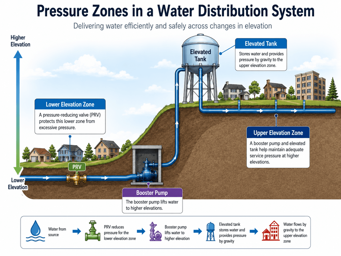
The terms “upper elevation zone” and “lower elevation zone” are often clearer than “high pressure” and “low pressure” because higher ground does not automatically mean higher pressure. In many systems, the upper elevation zone actually needs pumping or elevated storage to maintain adequate service pressure, while the lower elevation zone may need a pressure-reducing valve to prevent excessive pressure.
Pressure-zone boundaries are not just lines on a plan. They depend on valve positions, tank levels, pump controls, pressure-reducing valve settings, and whether operators can isolate areas without interrupting too many customers.
Water Distribution System Design Criteria Engineers Check
Water distribution system design criteria vary by utility, local standards, fire protection requirements, and project type. Still, the same categories are commonly checked: demand, pressure, fire flow, storage, head loss, pipe sizing, water age, redundancy, and maintenance access.
| Design criterion | What it affects | What engineers usually verify |
|---|---|---|
| Average day demand | Normal operating flow and storage turnover. | The system has reasonable flow paths without excessive water age in low-demand areas. |
| Maximum day demand | High seasonal or daily water use. | Pumps, tanks, and mains can support higher demand without unacceptable pressure loss. |
| Peak hour demand | Short-duration high demand. | Critical nodes maintain adequate residual pressure during the highest-use periods. |
| Fire-flow demand | Emergency flow available at hydrants. | Hydrants, mains, pumps, and storage can support fire flow while maintaining required residual pressure. |
| Pressure range | Customer service, pipe stress, leakage, and PRV needs. | High and low elevations are served within the utility’s allowable pressure range. |
| Pipe head loss | Available pressure at downstream users. | Pipe diameters and materials keep friction losses acceptable under controlling demand cases. |
| Storage volume | Reliability, pressure support, emergency supply, and operational flexibility. | Storage supports equalization, emergency needs, and fire protection while avoiding poor turnover. |
| Water age | Disinfectant residual, taste, odor, and water quality stability. | Dead ends, oversized mains, and tank cycling do not create avoidable stagnation problems. |
| Valve isolation | Maintenance and outage size. | Repairs can be isolated without shutting down an unnecessarily large service area. |
Fire Flow, Peak Demand, and Reliability
Fire flow is one of the most important practical checks in a water distribution system. A main that works well for normal household demand may not provide enough flow and pressure when a hydrant is flowing during a fire event.
Engineers often evaluate normal demand, maximum day demand, peak hour demand, and fire-flow scenarios separately. The controlling case may change depending on pipe size, tank level, pump operation, elevation, and how close the demand point is to a strong looped main.
- Normal demand: Checks everyday service and water age conditions.
- Peak hour demand: Checks pressure when many users draw water at the same time.
- Fire-flow demand: Checks whether hydrants can deliver emergency flow while residual pressure remains acceptable.
- Valve-closed condition: Checks whether maintenance or a main break removes a critical flow path.
Looped mains often perform better for fire flow because water can approach the hydrant from more than one direction. A dead-end main may experience larger pressure losses and less reliable flow during emergency demand.
Water Quality, Water Age, and Dead Ends
A water distribution system can change water quality after treatment. Water may sit in storage tanks, dead-end mains, oversized pipes, or low-demand areas long enough for disinfectant residual to decline. Sediment, corrosion products, biofilm, temperature, and pressure disturbances can also affect delivered water quality.
This is why distribution design includes more than hydraulic capacity. Engineers and operators consider water age, tank turnover, flushing access, dead-end management, backflow prevention, pipe material, and pressure stability. Maintaining positive pressure is especially important because pressure loss can increase vulnerability to contamination pathways.
| Water quality issue | Common distribution-system cause | Practical response |
|---|---|---|
| Low disinfectant residual | Long residence time, low demand, poor tank turnover, or dead ends. | Review flushing routes, tank operation, system turnover, and demand assumptions. |
| Taste or odor complaint | Stagnation, warm water, dead-end mains, or sediment disturbance. | Check water age, temperature, recent valve operations, and flushing history. |
| Discolored water | Flow reversal, main break repair, hydrant use, corrosion products, or sediment release. | Review recent field operations and develop a controlled flushing response. |
| High water age in storage | Oversized tanks, poor mixing, low cycling, or operating levels that stay too constant. | Evaluate tank mixing, fill-draw cycles, and storage volume relative to demand. |
| Backflow vulnerability | Pressure loss, cross-connections, or inadequate backflow prevention. | Maintain pressure, review backflow controls, and identify high-risk service connections. |
Oversizing every pipe can backfire. Larger pipes may reduce head loss, but if demand is low, they can also increase residence time and make it harder to maintain water quality in parts of the network.
Modeling Water Distribution Systems
Water distribution system modeling helps engineers evaluate pressure, flow, tank levels, pump operation, fire flow, water age, and system response under different operating conditions. A model represents the network as nodes, pipes, tanks, reservoirs, pumps, valves, elevations, and demands.
The model is only as good as the data behind it. Pipe diameter, material, roughness, valve status, pump curves, tank levels, elevations, and demand allocation can all change the result. That is why field calibration using hydrant tests, pressure logging, SCADA trends, tank data, and pump records is so important.
| Model element | What it represents | Common QA/QC check |
|---|---|---|
| Junction or node | A demand point, pipe connection, or hydraulic calculation location. | Elevation, demand allocation, and pressure output are reasonable. |
| Pipe | A water main with length, diameter, material, and roughness. | GIS length, diameter, connectivity, and roughness assumptions match available records. |
| Pump | A device that adds head to move water or serve a pressure zone. | Pump curve, controls, operating status, and backup assumptions are correct. |
| Tank or reservoir | A storage boundary that affects hydraulic grade and available supply. | Water level range, volume curve, overflow elevation, and controls are correct. |
| Valve | A flow control, isolation, pressure-reducing, or check device. | Valve status, setting, location, and zone boundary function are verified. |
For a broader modeling context, see Water Resources Modeling.
How Engineers Use Distribution System Analysis
Engineers evaluate water distribution systems during planning, design, expansion, rehabilitation, operations, and emergency response. The work may involve a spreadsheet check for a small extension or a calibrated hydraulic model for a full municipal network.
- New development review: Confirm that new demands can be served without reducing pressure or fire-flow availability elsewhere.
- Capital improvement planning: Identify undersized mains, aging pipes, weak pressure zones, and locations where looping improves reliability.
- Operations support: Test valve closures, tank operating levels, pump controls, and flushing plans before field changes are made.
- Water quality management: Evaluate dead ends, storage turnover, disinfectant residual trends, and areas with long water age.
Distribution analysis should include both hydraulic performance and operational reality. If a model assumes all valves are open and all pumps are available, it may miss the conditions that actually control reliability during maintenance or emergencies.
Simple Water Distribution System Design Example
Consider a new subdivision proposed on ground that is higher than the existing neighborhood. The existing main may provide enough flow during normal demand, but a peak-hour plus fire-flow check may show low residual pressure at the highest lots.
What the engineer checks
The engineer reviews the connection point, ground elevations, peak demand, fire-flow requirement, existing pipe diameter, tank operating level, pump capacity, and whether the new area can be looped back to another main. The analysis may show that a larger main alone is not enough if elevation is the controlling issue.
Possible design responses
The solution might be a looped connection, a booster pump, a new pressure zone, a higher storage operating level, or a combination of improvements. The right answer depends on whether the limiting problem is head loss, elevation, storage, fire-flow capacity, valve isolation, or water age.
Senior Engineer Review Checklist for Distribution Systems
A useful review does not stop at pipe diameter. The best checks ask whether the network can deliver flow, maintain pressure, preserve water quality, survive maintenance conditions, and be operated by real crews with real constraints.
Start with demand and service pressure, then check fire flow, elevation zones, storage, pump capacity, head loss, valve isolation, water age, and maintainability. If one condition fails, the fix may be a larger main, a looped connection, a different pressure-zone boundary, storage improvements, or operational controls.
| Review check | What to look for | Why it matters |
|---|---|---|
| Demand basis | Average day, maximum day, peak hour, and fire-flow assumptions are clearly separated. | Different demand cases can control different parts of the system. |
| Residual pressure | Critical nodes still have acceptable pressure during peak demand and fire-flow cases. | Low residual pressure can indicate undersized mains, excessive head loss, or weak pressure-zone support. |
| Storage operation | Tanks have practical operating levels, turnover, emergency reserve, and controls. | Storage supports pressure, demand balancing, and resilience, but poor turnover can harm water quality. |
| Pressure-zone boundary | PRVs, closed valves, booster pumps, and tanks define zones that can be operated and maintained. | Unclear zone boundaries can create pressure complaints, operational confusion, and hard-to-diagnose flow paths. |
| Looping and redundancy | Critical customers and hydrants are not served by a single fragile path where avoidable. | Looped mains improve reliability when valves close or pipe breaks occur. |
| Water age and dead ends | Low-demand areas, oversized pipes, dead-end mains, and poorly mixed tanks are identified. | Hydraulic success does not guarantee water quality success. |
| Valve isolation | Repair shutdowns affect a reasonable number of customers and leave critical routes available. | Good valve layout limits outage size and makes maintenance safer and faster. |
| Model calibration | Modeled pressures and flows are checked against hydrant tests, tank levels, pump data, or SCADA trends. | Uncalibrated models can look precise while representing the real system poorly. |
Water Distribution System Operation and Maintenance
Operation and maintenance determine whether the designed system continues to perform over time. Pipe networks age, valves seize, hydrants need testing, tanks require inspection, pumps wear, and demand patterns change as communities grow.
| Maintenance activity | Purpose | Distribution-system value |
|---|---|---|
| Valve exercising | Confirms valves can open and close when needed. | Reduces repair outage size and improves emergency response. |
| Hydrant testing and flushing | Checks flow availability and removes stagnant or sediment-laden water. | Supports fire protection, water quality, and model calibration. |
| Leak detection | Identifies hidden water loss and pipe deterioration. | Improves pressure management, asset planning, and non-revenue water control. |
| Tank inspection and cleaning | Checks structural condition, coating condition, sediment, and sanitary protection. | Protects storage reliability and delivered water quality. |
| Pump maintenance | Maintains capacity, efficiency, and reliable operation. | Protects pressure zones and critical supply routes. |
| Pressure monitoring | Tracks high pressure, low pressure, transients, and zone performance. | Helps diagnose complaints, leakage risk, and pressure-control problems. |
For related leakage and pressure-management context, see Water Loss Control.
Common Water Distribution System Problems
Water distribution system problems often appear as pressure complaints, discolored water, main breaks, hydrant flow limitations, storage turnover issues, or repeated leaks. The visible symptom is rarely the full cause, so engineers look at hydraulics, operations, materials, age, and recent field changes together.
| Observed problem | Likely engineering causes | Practical checks |
|---|---|---|
| Low pressure at high elevations | Insufficient hydraulic grade, booster pump limitations, high head loss, or weak pressure-zone definition. | Check tank level, pump operation, node elevation, valve position, and peak-demand conditions. |
| Excessive pressure in low areas | Large elevation drop, missing PRV, incorrect PRV setting, or pressure-zone leakage. | Review pressure logger data, PRV settings, zone boundaries, and customer complaints. |
| Discolored water after flow changes | Sediment disturbance, corrosion products, flow reversal, hydrant use, or main break repair. | Review recent flushing, hydrant use, valve operations, and affected pipe materials. |
| Repeated pipe breaks | Aging material, pressure cycling, corrosive soil, poor bedding, surge, or excessive operating pressure. | Compare break history, pressure transients, pipe age, soil conditions, and repair records. |
| Poor fire-flow results | Undersized mains, closed valves, long dead-end runs, weak storage, or pump capacity limits. | Check hydrant test data, model fire-flow scenarios, valve status, and available storage. |
| High water age | Dead ends, oversized mains, low demand, excessive storage volume, or poor tank mixing. | Review demand patterns, flushing routes, storage turnover, and disinfectant residual trends. |
Engineering Judgment and Field Reality
Real water distribution systems rarely behave exactly like clean textbook diagrams. Some valves may be closed without being updated in a model, old pipes may have unknown roughness, customer demand may differ from planning assumptions, and field crews may need isolation options that were not obvious during design.
Older systems also tend to include mixed pipe materials, abandoned connections, historical pressure-zone changes, and extensions added as development grew. A technically correct design drawing is not enough unless the system can be operated, maintained, flushed, repaired, and expanded without creating new problems.
The most important distribution system problems often occur during abnormal conditions: a tank is low, a pump is offline, a valve is closed, a hydrant is flowing, a main breaks, or demand peaks during hot weather. Good review checks those cases, not only the average-day condition.
When This Breaks Down
Simplified explanations of water distribution systems break down when the network becomes large, old, hilly, highly looped, or operationally complex. At that point, a simple source-to-customer diagram is useful for learning, but it does not capture every hydraulic path or operating constraint.
- Multiple pressure zones: A single pressure assumption can be misleading when ground elevations vary significantly.
- Closed or partially closed valves: Actual flow paths may differ from the mapped network if valve status is wrong.
- Fire-flow events: High flow can cause much larger head losses than normal customer use.
- Low-demand areas: Hydraulic capacity may be adequate while water age and disinfectant residual become the controlling issues.
- Aging infrastructure: Pipe roughness, tuberculation, leakage, and break history can dominate system performance.
Common Mistakes and Practical Checks
The most common mistakes come from treating the distribution system as either a simple pipe-sizing problem or a generic network diagram. In practice, the system is a hydraulic, operational, water quality, and maintenance asset all at once.
- Ignoring fire flow: Normal customer demand may not control the required pipe size or storage need.
- Overlooking dead ends: Dead-end mains can create low turnover and require planned flushing.
- Assuming all storage improves performance: Storage helps reliability, but poor turnover or mixing can increase water age.
- Forgetting valve isolation: A main may be hydraulically adequate but difficult to repair without shutting down a large area.
- Using a model without calibration: A model should be checked against field data such as hydrant tests, pressure logging, tank levels, or pump records.
Do not evaluate a distribution system using only average demand. Peak hour, maximum day, fire-flow, pump-outage, and valve-closed conditions often reveal the real weaknesses.
Useful References and Design Context
Water distribution system design and operation depend on local criteria, utility standards, fire protection requirements, health regulations, and field data. A national reference is most useful for understanding distribution-system water quality issues and the types of tools agencies use to evaluate them.
- U.S. Environmental Protection Agency: EPA drinking water distribution system tools and resources provides distribution-system resources related to water quality, operation, and system management.
- Project-specific criteria: Final design decisions usually depend on utility standards, fire-flow requirements, local review criteria, pressure-zone plans, and available field data.
- Engineering use: Engineers combine reference guidance with hydraulic modeling, hydrant testing, pressure monitoring, asset condition, and operator knowledge to evaluate real distribution networks.
Frequently Asked Questions
A water distribution system is the network of pipes, pumps, storage tanks, valves, hydrants, meters, and service lines that delivers treated water from a source or treatment plant to customers. Engineers design these systems to maintain pressure, provide enough flow for normal and fire demand, preserve water quality, and keep service reliable during maintenance or emergencies.
The main components include finished water storage, pump stations, transmission mains, distribution mains, elevated or ground storage tanks, valves, hydrants, pressure control devices, meters, and service lines. Each part supports a different role, such as moving large flows, maintaining pressure, isolating repairs, supporting fire protection, or connecting individual users.
Common types include branched systems, grid systems, looped systems, radial systems, gravity systems, pumped systems, and combined systems. Real municipal systems are often hybrids because service areas grow over time and must adapt to terrain, storage, pressure zones, fire-flow needs, and existing infrastructure.
Pressure is maintained through storage elevation, pump head, booster stations, pressure zones, and control valves. Elevated tanks provide gravity pressure, pumps add energy where elevation or distance requires it, and pressure-reducing valves protect lower areas from excessive pressure.
Water age matters because treated water can lose disinfectant residual, warm up, stagnate, or develop taste, odor, and water quality problems as it remains in the system. Dead ends, oversized pipes, low demand, and poorly mixed tanks can all increase water age.
Summary and Next Steps
Water distribution systems are the delivery networks that connect treated water to actual users. Their performance depends on pipes, pumps, tanks, valves, pressure zones, hydrants, and service lines working together as one hydraulic and operational system.
The most important design and review issues are pressure, flow, fire protection, storage, head loss, water age, redundancy, valve isolation, modeling accuracy, and maintainability. A strong system is not only capable of moving water; it is also reliable, controllable, repairable, and protective of water quality.
Where to go next
Continue your learning path with related Turn2Engineering resources.
-
Water Infrastructure
See how distribution systems fit into the larger water infrastructure network of treatment, storage, conveyance, and management.
-
Water Loss Control
Learn how leakage, pressure management, and non-revenue water affect real distribution system performance.
-
Hazen-Williams Equation
Review the common empirical equation used to estimate friction head loss in pressurized water pipes.