Key Takeaways
- Core idea: Power transmission moves large amounts of electrical energy from generation sources to substations and load centers, usually at high voltage.
- Engineering use: Transmission planning connects generation, bulk loads, substations, interties, and regional grids while maintaining voltage, stability, reliability, and thermal limits.
- What controls it: Voltage level, current, conductor resistance, line reactance, distance, power factor, thermal rating, stability margin, and right-of-way constraints all affect transmission performance.
- Practical check: High voltage reduces current and losses, but real transmission design is also limited by insulation, clearances, sag, reactive power, protection, permitting, and system stability.
Table of Contents
Introduction
Power transmission is the bulk movement of electrical energy from generating sources to substations and major load centers, usually through high-voltage transmission lines. Transmission systems use higher voltage to reduce current, limit \(I^2R\) losses, and move power efficiently over long distances before voltage is stepped down for distribution.
How Power Transmission Works
Notice that transmission is not just the wire between towers. It includes transformers, substations, switching equipment, protection devices, and the operating controls that keep power flowing safely.
What Is Power Transmission?
Power transmission is the bulk transfer stage of an electric power system. It carries energy from generating resources to substations and regional networks before that energy is delivered to homes, commercial buildings, industrial facilities, and other end users through lower-voltage distribution systems.
In practical electrical engineering, transmission is about more than moving energy from one point to another. Engineers must maintain voltage, limit losses, prevent overloaded conductors, isolate faults, preserve system stability, and coordinate many pieces of equipment across long distances. A transmission line that looks simple in the field may represent a major system constraint in a load flow model.
The Transmission Path from Source to Load
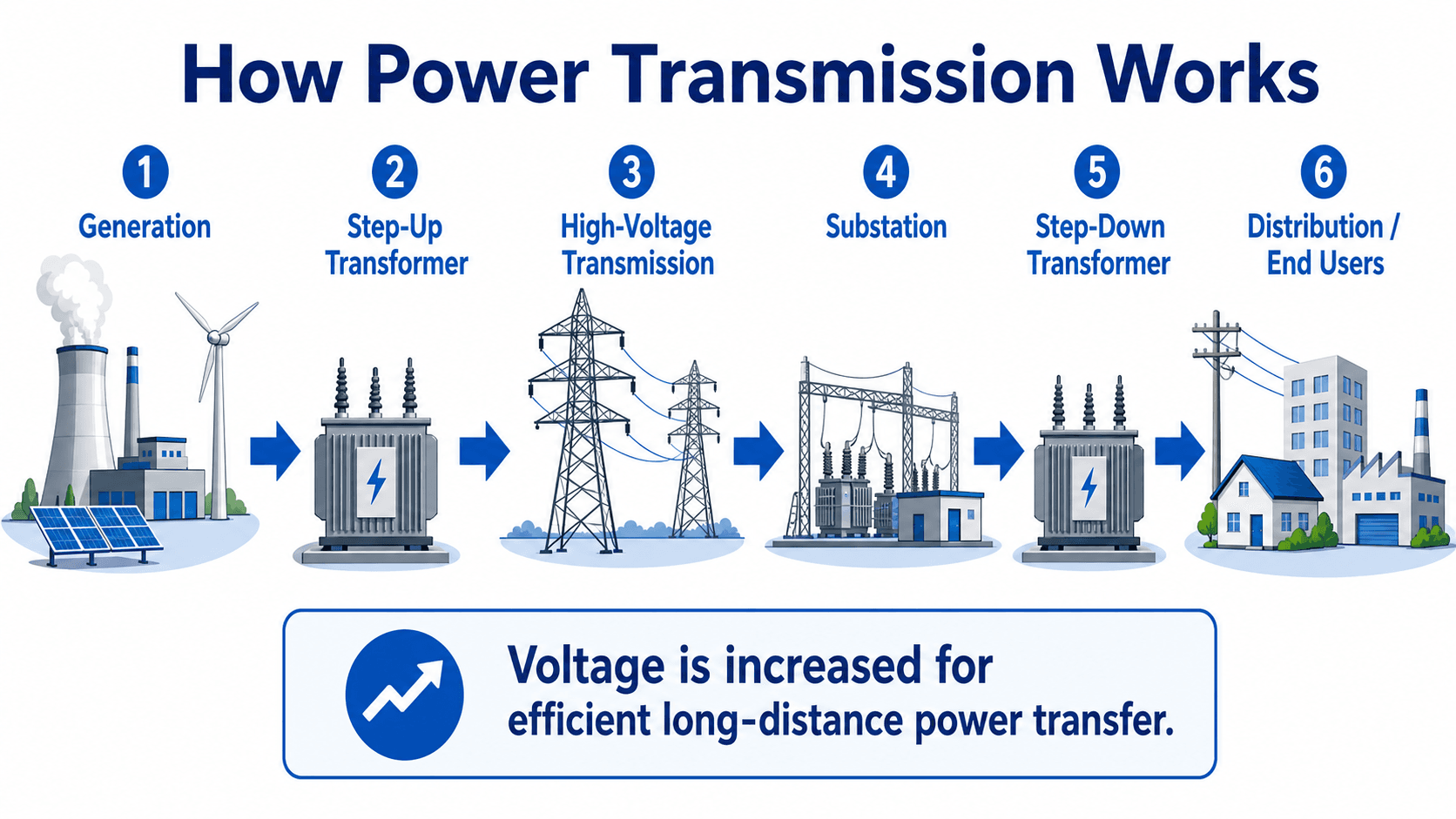
A typical power transmission path starts at a generating plant or renewable energy facility. The generator output is stepped up to a higher voltage, transmitted across overhead lines or cables, routed through switching substations, and eventually stepped down for distribution. The reason for stepping voltage up is simple: for the same power transfer, higher voltage means lower current.
Generation and Step-Up Transformation
Generators usually produce power at voltages lower than the long-distance transmission level. A step-up transformer increases voltage so the same megawatts can be moved with less current. This reduces conductor heating, improves efficiency, and allows power to travel farther before voltage support or additional infrastructure is required.
Transmission Lines and Substations
Transmission lines carry power between buses, substations, generating plants, and interconnections. Substations transform voltage, switch circuits, connect lines, monitor system conditions, and isolate faults. In a real grid, substations are not passive waypoints; they are operating nodes that control how power can be routed and protected.
Step-Down Transformation and Distribution Interface
Near the load area, step-down transformers reduce voltage to subtransmission or distribution levels. From there, the distribution line network delivers power locally. This boundary matters because transmission planning focuses on bulk transfer, while distribution planning focuses on feeders, service reliability, customer connections, and final utilization voltage.
Why High Voltage Reduces Transmission Losses
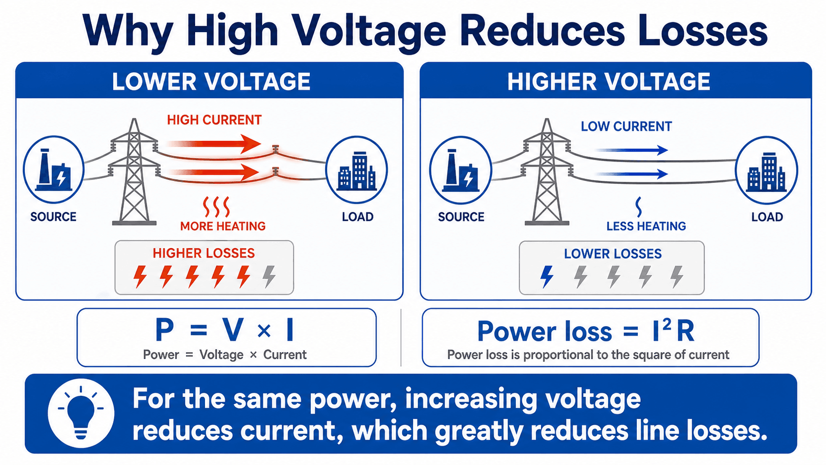
The most important power transmission concept is that current drives resistive heating. For a given amount of real power, increasing voltage allows current to decrease. Since line losses rise with the square of current, a modest reduction in current can create a large reduction in heat loss.
In three-phase transmission, the same idea is usually written in terms of line-to-line voltage:
This is why a transmission voltage increase can sharply reduce current and line heating. It does not mean higher voltage is always the only answer; it means voltage, insulation, clearances, equipment cost, line routing, and substation design have to be balanced together.
- P Real power transferred, usually in watts, kilowatts, or megawatts.
- V Voltage. In three-phase transmission, line-to-line voltage is commonly used.
- I Line current. Lower current reduces conductor heating and voltage drop.
- R Conductor resistance over the relevant line length and temperature condition.
- \(\cos(\theta)\) Power factor, which affects how much useful real power is delivered for a given voltage and current.
Power Transmission vs Power Distribution
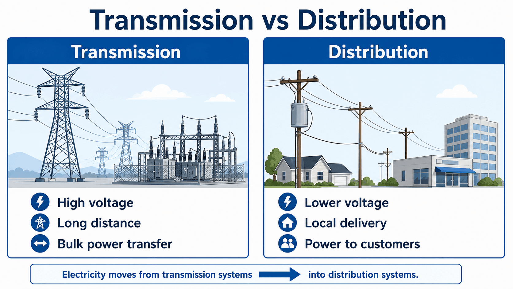
Transmission and distribution are often grouped together, but they solve different engineering problems. Transmission is the high-voltage backbone that moves bulk power across regions. Distribution is the lower-voltage local network that delivers power to individual customers and smaller facilities.
| Category | Power Transmission | Power Distribution |
|---|---|---|
| Primary role | Bulk transfer between generation, substations, grid regions, and large load centers. | Local delivery from distribution substations to customers and end-use equipment. |
| Typical voltage | High voltage, extra-high voltage, or HVDC depending on system design. | Medium-voltage feeders stepped down to low-voltage service levels. |
| Main equipment | Transmission towers, high-voltage conductors, substations, transformers, relays, breakers, reactors, and compensation equipment. | Feeders, poles, pad-mounted transformers, service drops, reclosers, fuses, meters, and customer service equipment. |
| Engineering focus | Thermal limits, voltage stability, angular stability, reactive power, fault clearing, congestion, and interconnection planning. | Voltage drop, feeder loading, protection coordination, service reliability, customer growth, and local equipment ratings. |
For a deeper look at local delivery equipment and lower-voltage network behavior, see the related Turn2Engineering guide on distribution lines.
Types of Power Transmission
Power transmission can be classified by current type, construction method, voltage level, and grid role. These categories help engineers compare efficiency, cost, reliability, right-of-way needs, maintenance access, and long-term operating flexibility.
| Type | Where it is used | Key engineering tradeoff |
|---|---|---|
| Overhead AC transmission | Most long-distance grid corridors and regional bulk power paths. | Usually cost-effective and maintainable, but requires right-of-way, clearances, structures, and vegetation management. |
| Underground transmission | Dense urban corridors, constrained routes, and visually sensitive areas. | Reduces visual impact but increases cost, thermal design complexity, and repair difficulty. |
| Submarine transmission | Island connections, offshore wind export, and underwater crossings. | Often favors HVDC for long distances because AC cable charging current becomes limiting. |
| HVDC transmission | Long-distance point-to-point transfer, asynchronous interties, and offshore applications. | Provides controllable power flow but requires expensive converter stations and specialized controls. |
Common Transmission Voltage Categories
Voltage categories vary by country, utility, and system standard, so exact breakpoints should not be treated as universal. In practice, transmission systems are grouped by function and voltage class rather than by one global voltage table.
| Category | Typical use | Practical note |
|---|---|---|
| Subtransmission | Regional transfer between transmission and distribution levels. | Often bridges the gap between the bulk grid and local distribution substations. |
| High-voltage transmission | Bulk transfer across utility networks and load regions. | Used where distribution voltage would create excessive current, voltage drop, and loss. |
| Extra-high-voltage transmission | Large regional transfer, long corridors, and major interconnections. | Requires larger clearances, stronger insulation coordination, and more complex substations. |
| HVDC transmission | Long-distance, submarine, or controllable point-to-point transmission. | Voltage selection depends heavily on converter design, power level, distance, route, and project economics. |
Main Components of a Power Transmission System
A transmission system is a coordinated network of conductors, structures, substations, transformers, protection equipment, monitoring systems, and operating procedures. The visible towers and wires are only part of the system.
| Component | What it does | Why it matters |
|---|---|---|
| Conductors | Carry phase current between transmission nodes. | Resistance, ampacity, temperature, sag, and mechanical strength affect losses and clearances. |
| Towers and structures | Support conductors, insulators, shield wires, and clearances. | They control span length, right-of-way width, ground clearance, wind loading, and constructability. |
| Insulators | Electrically separate energized conductors from grounded structures. | They must withstand voltage stress, contamination, weather, and mechanical loading. |
| Transformers | Step voltage up or down between system levels. | They make efficient AC transmission practical and often become major system assets with long lead times. |
| Substations | Switch, transform, protect, meter, and route power. | They form the grid nodes where lines, transformers, breakers, relays, and control systems interact. |
| Protection systems | Detect faults and trip breakers quickly. | Correct protection prevents equipment damage and helps avoid cascading outages. |
| Reactive power equipment | Controls voltage and reactive power flow. | Capacitor banks, reactors, STATCOMs, and other equipment help maintain voltage stability. |
Protection equipment is especially important because a transmission fault can affect more than one local feeder. For a deeper look at fault detection and clearing, see transmission line protection.
Transmission Line Parameters
Transmission lines are modeled using resistance, inductance, capacitance, and conductance. These parameters explain why a real line does more than simply carry current from one point to another. They also help engineers understand losses, voltage drop, charging current, reactive power, and stability behavior.
| Parameter | What it represents | Why it matters in transmission |
|---|---|---|
| Resistance, R | Opposition to current flow in the conductor. | Creates real power loss and conductor heating. |
| Inductance, L | Magnetic field energy storage around conductors. | Creates reactance and affects voltage drop, reactive power, and power transfer limits. |
| Capacitance, C | Electric field coupling between conductors and ground. | Creates charging current, especially important for long lines, underground cables, and submarine cables. |
| Conductance, G | Leakage path through insulation, air, or surrounding medium. | Usually small, but relevant for insulation performance, leakage, contamination, and detailed modeling. |
Short, medium, and long transmission lines are not modeled with the same level of detail. As line length increases, capacitance and reactive effects become harder to ignore.
AC Transmission, HVDC Transmission, and When Each Makes Sense
Most electric grids use AC transmission because transformers make voltage conversion efficient and because generation, substations, and distribution systems are largely built around AC. High-voltage direct current, or HVDC, is used when its controllability or loss profile justifies the added cost and complexity of converter stations.
| Transmission type | Best fit | Important tradeoff |
|---|---|---|
| AC transmission | Interconnected grids, regional networks, standard substation interfaces, and most bulk power systems. | Long AC lines are affected by reactance, reactive power, charging current, voltage control, and stability limits. |
| HVDC transmission | Very long-distance transfer, submarine cables, asynchronous grid ties, offshore wind export, and controllable point-to-point power flow. | Converter stations are expensive and complex, so HVDC usually needs a strong technical or economic reason. |
| Underground or submarine transmission | Urban corridors, sensitive routes, underwater crossings, or places where overhead lines are impractical. | Thermal limits, charging current, repair access, installation cost, and route constraints become major design issues. |
To compare the broader behavior of alternating-current and direct-current systems, see AC vs DC power systems.
Do not assume HVDC is automatically better because it sounds more advanced. The decision depends on route length, power level, controllability needs, converter cost, land constraints, losses, reliability requirements, and how the project connects to the surrounding AC grid.
What Controls Transmission Line Performance?
Transmission line performance is controlled by electrical, thermal, mechanical, environmental, and operational limits at the same time. A line may be acceptable by ampacity but constrained by voltage stability, reactive power, sag clearance, relay settings, or regional power flow.
| Factor | Why it matters | Engineering implication |
|---|---|---|
| Voltage level | Higher voltage reduces current for a given power transfer. | Lower current reduces \( I^2R \) losses, but insulation, clearances, structures, and equipment ratings become more demanding. |
| Conductor resistance | Resistance creates real power loss and heating. | Material, size, temperature, and line length directly affect efficiency and thermal loading. |
| Line reactance | Reactance affects voltage drop, reactive power, and power transfer limits. | Long AC lines are often limited by stability and voltage behavior, not just conductor heating. |
| Thermal rating | Current heats the conductor and increases sag. | Excessive temperature can violate ground clearance or reduce equipment life. |
| Power factor and reactive power | Reactive power occupies current capacity and affects voltage. | Voltage support may require capacitor banks, reactors, synchronous condensers, STATCOMs, or operating changes. |
| Fault duty and protection | Transmission faults must clear quickly and selectively. | Breaker ratings, relay settings, communication channels, and coordination affect system reliability. |
Basic Power Transmission Equations
Transmission analysis can become complex, but several equations explain the core behavior. These equations are not a substitute for full load flow, short-circuit, stability, or protection studies, but they help readers understand why voltage, current, resistance, and reactance matter.
Apparent power \(S\) describes the voltage-current capacity involved in a three-phase system. Real power depends on power factor, while reactive power affects voltage support and system stability.
For a balanced three-phase line, total resistive loss is approximately three times the per-phase \(I^2R\) loss. If current doubles, resistive loss increases by about four times.
A simplified power-angle relationship shows why line reactance and phase angle matter for AC transmission. In real planning studies, engineers evaluate thermal ratings, voltage limits, contingency cases, reactive power, and stability margins together.
Power Transmission Design Review Checklist
A practical transmission review should check more than whether the line can carry the expected current. Engineers review electrical loading, voltage behavior, stability, protection, constructability, and the field conditions that can change the answer.
Start with the power transfer need, choose a feasible voltage class, model load flow and contingencies, check thermal and voltage limits, review fault duty and protection, evaluate structure and conductor constraints, then confirm right-of-way, permitting, access, and maintainability.
| Check or decision | What to look for | Why it matters |
|---|---|---|
| Voltage class selection | Power transfer level, route length, interconnection voltage, equipment availability, and expansion plans. | Voltage drives current, losses, insulation, clearances, substation cost, and future capacity. |
| Thermal loading | Normal and contingency current compared with conductor, transformer, breaker, switch, and terminal ratings. | A line rating is only as useful as the weakest series element in the path. |
| Voltage and reactive power | Receiving-end voltage, voltage stability margin, reactive support, shunt reactors, capacitor banks, and switching strategy. | Long AC lines can be voltage-limited even when conductors are not thermally overloaded. |
| Protection coordination | Line relays, breaker interrupting ratings, communication channels, reclosing logic, and backup protection. | Faults must clear quickly without tripping more of the grid than necessary. |
| Sag and clearance | Maximum conductor temperature, span length, terrain, wind, ice, and required clearances. | A thermally loaded conductor can sag enough to create a safety or reliability problem. |
| Right-of-way and access | Route constraints, vegetation, roads, structures, environmental limits, and maintenance access. | A technically sound line still needs a buildable, maintainable corridor. |
For studies that evaluate power flow, bus voltage, line loading, and system constraints, see the related guide on load flow analysis.
Worked Example: Why Current Reduction Matters
Consider a simplified balanced three-phase transmission case. Suppose a line must transfer 100 MW at a power factor of 0.95. Compare the approximate current at 69 kV and 230 kV.
Current at 69 kV
Current at 230 kV
Engineering Meaning
The 230 kV case carries the same real power at roughly 30 percent of the current. Since resistive losses scale with current squared, the loss reduction can be significant. In real projects, the higher-voltage option also brings higher equipment cost, larger clearances, more insulation requirements, and different substation constraints.
Why Power Transmission Matters for the Modern Grid
Transmission is becoming more important as generation and load patterns change. Renewable generation is often located far from major load centers, large data centers can create concentrated demand growth, and aging grid corridors may not have enough capacity for new interconnections.
- Remote wind, solar, hydro, and other generation resources often need long transmission paths to reach load centers.
- Transmission congestion can prevent lower-cost generation from reaching customers even when generation exists.
- Large new loads can require transmission upgrades, voltage support, or new substations before service is practical.
- HVDC links, dynamic line ratings, advanced power electronics, and grid-enhancing technologies can improve controllability and transfer capability in some systems.
- Transmission planning must account for reliability, contingency performance, future growth, permitting, and long equipment lead times.
A power project is not useful to the grid unless transmission capacity exists to move its output. Interconnection studies often reveal that the limiting issue is not generation equipment but the transmission network around it.
What Readers Commonly Confuse
Power transmission uses familiar words like voltage, current, power, capacity, and losses, but these terms are easy to mix up. A few distinctions make the topic much easier to understand.
| Confusion | Correct explanation | Practical check |
|---|---|---|
| Transmission vs distribution | Transmission is bulk high-voltage transfer; distribution is local lower-voltage delivery. | Ask whether the system is moving regional power or serving local customers. |
| Voltage vs power | High voltage does not mean more power by itself; power depends on voltage, current, and power factor. | Use the three-phase power equation when evaluating power transfer. |
| Line rating vs system capacity | A conductor rating is not the same as transfer capability; voltage stability and contingency limits may control. | Check thermal, voltage, stability, and protection constraints together. |
| AC vs HVDC | HVDC is not automatically better; it depends on distance, controllability, converter cost, and interconnection needs. | Compare the full project, not only line losses. |
Engineering Judgment and Field Reality
Textbook explanations often make power transmission look like a clean source-to-load path. Real grids are meshed, constrained, and operated under changing conditions. Load changes hour by hour, generators dispatch differently, renewable output varies, outages remove lines from service, and one overloaded interface can redirect power through unexpected paths.
A transmission corridor that works under normal conditions may fail a contingency review. Engineers often design and operate for the loss of a major line, transformer, or generator, not just the expected everyday flow.
Field conditions also affect physical line behavior. Hot weather can reduce thermal margins, wind can cool conductors but load structures, ice can increase mechanical loading, vegetation can threaten clearances, and difficult access can delay restoration after storms. Good transmission design connects electrical calculations with the physical realities of the route.
When This Breaks Down
The simple explanation “raise voltage to reduce current and losses” is useful, but it is incomplete. Transmission performance can break down when the system is limited by stability, voltage control, protection, thermal sag, short-circuit duty, or practical route constraints.
- Very long AC lines can require reactive compensation because capacitance, inductance, and voltage stability become dominant.
- High current can create conductor heating and sag problems before equipment appears overloaded on a simple power calculation.
- Fault current and relay coordination can limit how a line or substation can be connected and operated.
- Permitting, right-of-way, environmental constraints, and constructability can control the final design as much as electrical calculations.
- Underground or submarine transmission may be limited by thermal dissipation, cable charging current, repair access, and installation cost.
Common Mistakes and Practical Checks
Power transmission is often oversimplified because the basic high-voltage idea is easy to remember. The most common mistakes happen when readers ignore the difference between real power, apparent power, reactive power, physical conductor limits, and system operating limits.
- Confusing transmission with distribution and using local feeder assumptions for bulk power lines.
- Using \(P = VI\) without considering three-phase systems, power factor, or line-to-line voltage.
- Assuming conductor ampacity is the only limit when voltage stability, relay settings, or contingency performance may control.
- Ignoring temperature effects on resistance, sag, and line ratings.
- Assuming HVDC is always better without accounting for converter stations, interconnection needs, operating objectives, and project economics.
Do not evaluate a transmission path using only one equation. A real transmission decision should consider losses, voltage, thermal limits, stability, protection, clearances, right-of-way, reliability criteria, and the surrounding grid.
Useful References and Design Context
Power transmission references are most useful when they clarify how the grid moves electricity from generation to customers and where transmission ends and distribution begins. Detailed project design still depends on utility standards, interconnection requirements, planning criteria, and applicable codes.
- U.S. Energy Information Administration: EIA electricity delivery to consumers is a useful plain-language authority reference for how electricity moves from generating stations through high-voltage transmission lines and then into lower-voltage distribution systems.
- Project-specific criteria: Utility planning standards, interconnection requirements, operating guides, protection philosophy, environmental permits, and route constraints often control the final transmission design.
- Engineering use: Engineers use these references with load flow studies, stability studies, short-circuit analysis, insulation coordination, line rating calculations, and protection coordination.
Frequently Asked Questions
Power transmission is the bulk movement of electrical energy from generating sources to substations or major load centers, usually through high-voltage overhead lines, underground cables, or HVDC links. It is the grid stage between power generation and lower-voltage distribution.
Electricity is transmitted at high voltage because higher voltage allows the same power to move with lower current. Since conductor heating losses are proportional to current squared, reducing current greatly reduces line losses and makes long-distance transfer more practical.
Transmission moves bulk power over long distances at high or extra-high voltage, while distribution delivers lower-voltage power from substations to homes, businesses, and local loads. Transmission is the backbone network; distribution is the local delivery network.
Power transmission losses are mainly caused by conductor resistance, transformer losses, corona effects, leakage, reactive power flow, and equipment inefficiencies. The most important simple loss relationship is \(I^2R\), which means resistive line losses rise with the square of current.
Most grid transmission is AC because transformers make voltage conversion efficient and economical. HVDC transmission is used when controllable long-distance transfer, submarine cables, asynchronous grid ties, or lower losses over very long routes justify converter station cost.
Summary and Next Steps
Power transmission is the high-voltage stage of the electric grid that moves bulk energy from generation sources to substations, interconnections, and major load centers. Its central engineering idea is that higher voltage reduces current for the same power transfer, which can greatly reduce resistive losses.
A strong understanding of transmission requires more than the loss equation. Engineers also review voltage behavior, reactive power, stability, thermal ratings, sag, protection, line parameters, equipment ratings, right-of-way, and contingency performance. The best transmission decisions balance efficiency, reliability, constructability, maintainability, and long-term grid flexibility.
Where to go next
Continue your learning path with related Turn2Engineering resources.
-
Power Generation
Learn how electrical energy is produced before it enters the transmission network.
-
AC vs DC Power Systems
Compare AC and DC behavior, applications, advantages, and limitations in electrical power systems.
-
Transmission Line Protection
Learn how relays, breakers, and communication systems detect and isolate transmission faults.