
Key Takeaways
- Core idea: Septic tank design determines the tank volume, internal layout, inlet and outlet details, and drainfield connection needed to treat household wastewater onsite.
- Engineering use: Designers use estimated wastewater flow, tank storage, baffle layout, soil conditions, and drainfield capacity together instead of treating the tank as an isolated box.
- What controls it: Bedroom count, daily design flow, detention time, local minimum tank size, sludge and scum accumulation, groundwater, soil loading rate, and available drainfield area usually control the design.
- Practical check: A larger tank can improve storage and settling, but it does not fix a poor drainfield, shallow groundwater, compacted soil, failed baffles, or missing maintenance access.
Table of Contents
Introduction
Septic tank design determines the tank volume, internal layout, inlet and outlet details, and drainfield connection needed to treat household wastewater onsite. A complete design estimates daily flow, provides detention time for settling, stores sludge and scum, protects the outlet from solids, and verifies that the soil absorption area can accept the effluent.
Septic Tank Design Process Diagram
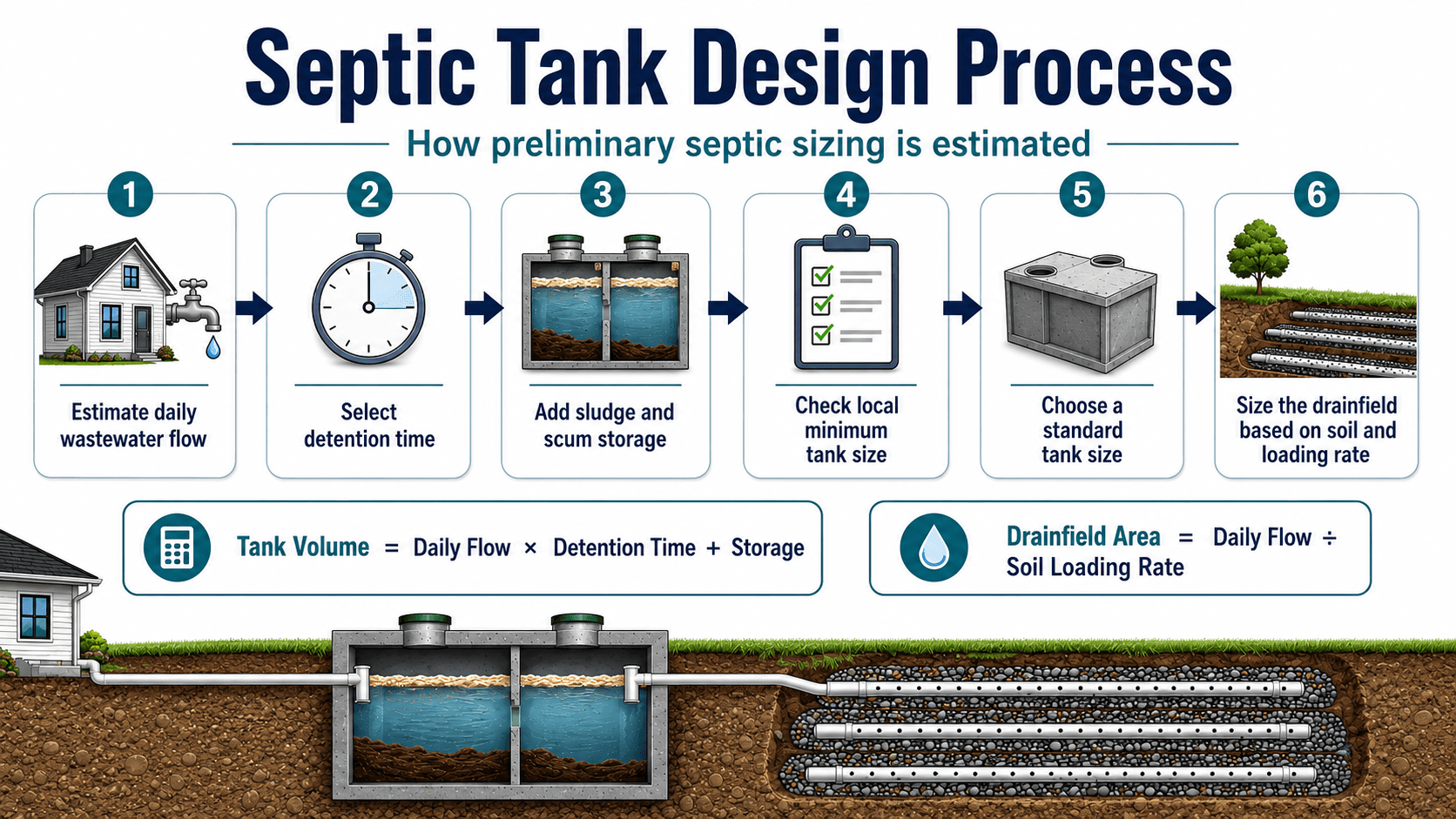
Notice that the tank and drainfield are part of the same design path. The tank separates solids from liquid, but the soil absorption area controls whether the clarified effluent can be dispersed without surfacing, backing up, or reaching groundwater too quickly.
What is Septic Tank Design?
Septic tank design converts a wastewater demand into a physical onsite treatment layout. The tank receives sewage from the building, slows the flow, allows heavier solids to settle as sludge, allows fats and grease to float as scum, and sends clarified liquid effluent toward a soil absorption system.
In water resources engineering, septic tank design sits between hydraulics, wastewater treatment, soil infiltration, and groundwater protection. The tank is not a complete treatment plant by itself. It is the primary settling and separation unit in a larger onsite wastewater system that also depends on the distribution box, drainfield trenches, soil profile, groundwater separation, and long-term maintenance access.
A good septic tank design is not simply the biggest tank that fits. It is a coordinated design that gives solids time to separate while protecting the downstream soil absorption system from clogging and hydraulic overload.
Septic Tank Components and Cross-Section
A septic tank cross-section shows how the tank separates wastewater into floating scum, liquid effluent, and settled sludge. The important design details are not only the tank volume, but also where the wastewater enters, where effluent leaves, how the tank is divided, and how the tank can be accessed for maintenance.
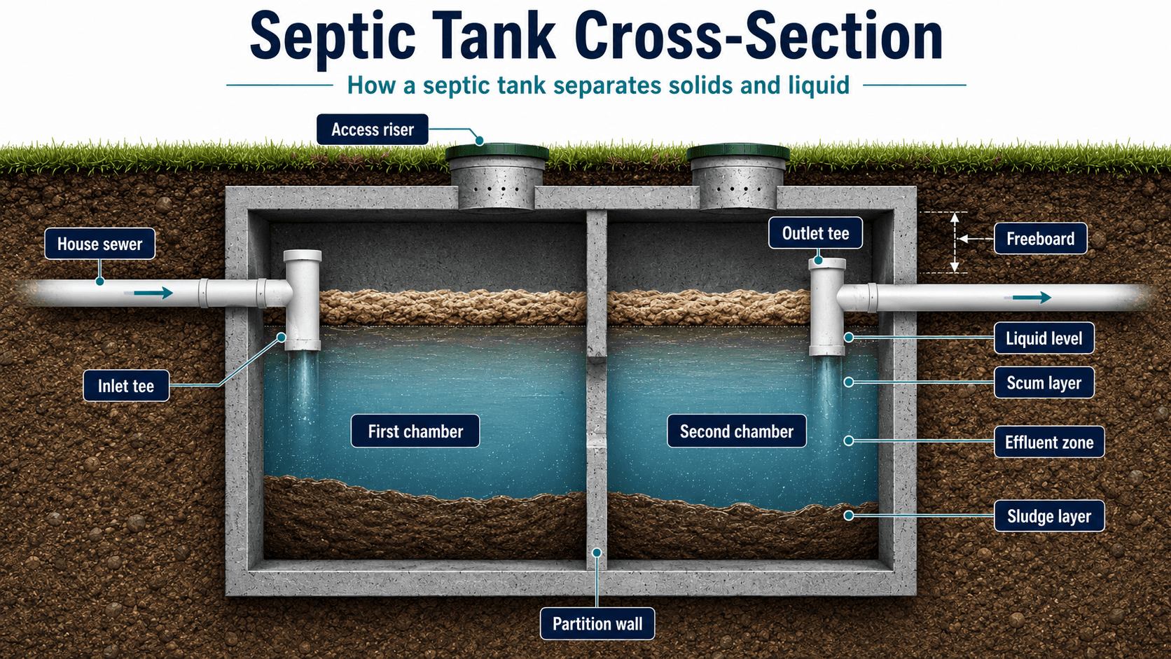
A septic tank design drawing is usually shown as both a plan view and a section view. The section view explains liquid level, freeboard, inlet tee, outlet tee, scum layer, sludge layer, and chamber separation, while the plan view shows tank location, pipe routing, access lids, distribution box, and drainfield alignment.
| Tank component | Design purpose | What goes wrong if it is overlooked |
|---|---|---|
| Inlet tee | Reduces turbulence and directs incoming wastewater below the floating scum layer. | Incoming flow can disturb settled solids and short-circuit toward the outlet. |
| Outlet tee | Draws effluent from the clearer middle liquid zone. | Floating scum or suspended solids can leave the tank and clog the drainfield. |
| Partition wall | Improves flow control and solids retention by separating the tank into chambers. | Poor chamber layout can reduce settling performance and increase solids migration. |
| Access riser | Allows inspection, pumping, and maintenance without excavating buried lids. | Maintenance is delayed or skipped because access is difficult. |
| Effluent filter | Provides extra outlet protection by catching solids before they enter the drainfield. | A clogged or missing filter can cause backups or send solids into the distribution system. |
| Freeboard | Provides space above the operating liquid level inside the tank. | Incorrect elevations can reduce working volume or create backup risk. |
Scum, effluent, and sludge zones
The scum layer contains floating fats, oils, grease, and light solids. The sludge layer contains settled solids. The effluent zone between them is the liquid layer that should leave the tank. Septic tank design tries to keep the outlet drawing from this middle zone, not from the floating or settled solids layers.
Why baffles and tees matter
Inlet and outlet tees are small compared with the tank volume, but they strongly affect performance. The inlet tee reduces direct jetting and turbulence. The outlet tee helps keep scum from entering the drainfield pipe. If either detail is missing, damaged, or submerged incorrectly, the tank may still have enough volume but perform poorly.
Septic System Layout from House to Drainfield
The tank layout only makes sense when it is connected to the full onsite system. Wastewater leaves the house through a building sewer, enters the septic tank, exits as clarified effluent, passes through a distribution box or header, and then spreads into perforated pipes placed in gravel or approved drainfield media.
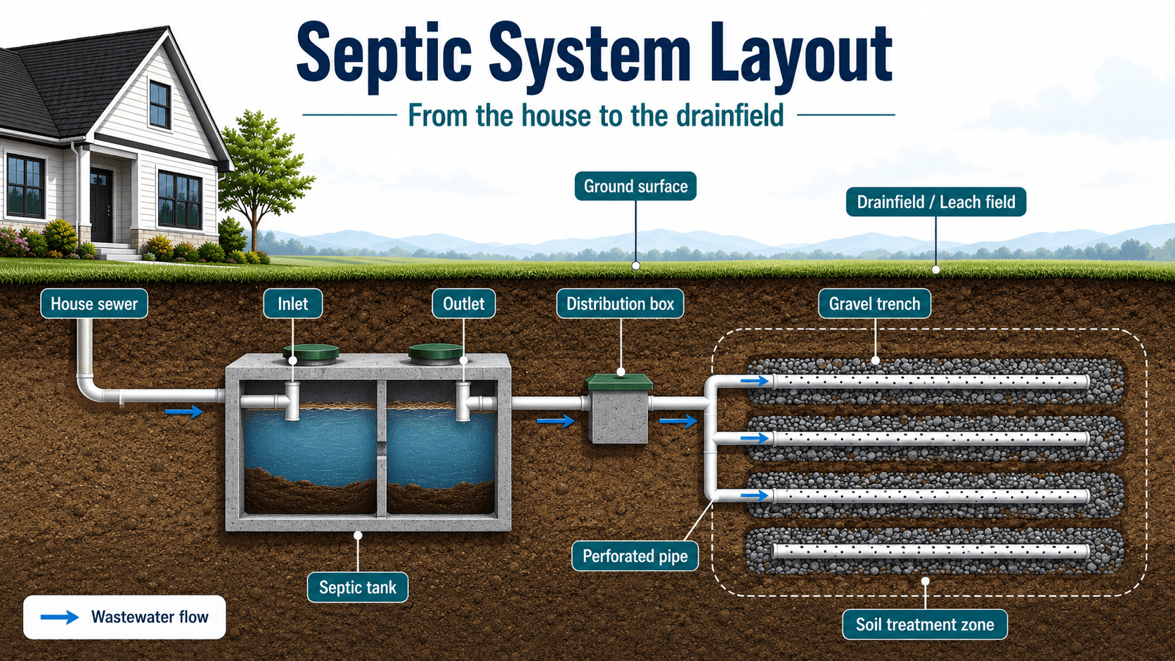
Tank design and drainfield design are connected
A septic tank can reduce solids loading to the drainfield, but it cannot create soil capacity. If the soil loading rate is low, the groundwater table is shallow, the site is steep, or the drainfield area is too small, simply increasing tank volume will not solve the disposal problem.
Why distribution matters
A drainfield depends on even effluent distribution. If one trench receives most of the flow, it can become saturated while other trenches remain underused. The distribution box, pipe slopes, trench elevations, and flow split details are therefore part of the practical design review.
What Makes a Good Septic Tank Design?
A good septic tank design gives wastewater enough time and space to separate while protecting the downstream drainfield. It should be easy to inspect, large enough for the design flow, coordinated with site soils, and detailed well enough that construction does not undermine the intended flow path.
- Enough tank volume for design flow and detention time.
- Additional capacity for sludge and scum accumulation between maintenance intervals.
- Correct inlet tee and outlet tee placement to reduce turbulence and solids carryover.
- A chamber layout that improves settling and protects the outlet.
- Outlet protection, such as an effluent filter where required or appropriate.
- A gravity flow path with pipe slopes and elevations that prevent backup.
- A drainfield sized to the approved soil loading rate.
- Setbacks from wells, buildings, property lines, surface water, and traffic areas.
- Accessible risers and lids for inspection and pumping.
- Protection from stormwater, compaction, root damage, and vehicle loading.
Inputs Needed for Septic Tank Design
Septic tank design starts with flow, but it does not end there. A complete design uses building information, site conditions, soil evaluation, local requirements, and maintenance access to select a tank and locate the rest of the system.
| Design input | Typical source | How it affects the design |
|---|---|---|
| Number of bedrooms | Building plan, permit basis, or residential design criteria. | Often controls preliminary residential design flow. |
| Fixture count | Plumbing plan or fixture-unit method. | May increase the design flow beyond the bedroom-based estimate. |
| Occupancy and use pattern | Residential use, rental pattern, commercial use, or assembly occupancy. | Changes peak loading, wastewater strength, and short-term flow variation. |
| Soil loading rate | Soil evaluation, percolation data, or local onsite wastewater criteria. | Controls required drainfield area and whether a conventional layout is feasible. |
| Groundwater and bedrock depth | Site evaluation, test pit, soil profile, or local records. | Controls vertical separation and may require an alternative system layout. |
| Slope and surface drainage | Site survey, grading plan, and field observation. | Affects tank placement, pipe routing, drainfield geometry, and stormwater conflicts. |
| Local minimum tank size | State, county, or local onsite wastewater requirements. | Sets the minimum acceptable tank volume regardless of a simplified calculation. |
Why local design criteria matter
Septic tank design requirements vary because soil, groundwater, climate, water use, and public health rules vary by location. Local criteria may control minimum tank volume, bedroom-based flow, fixture-unit flow, setbacks, drainfield loading rate, reserve area, and whether an alternative system is required.
What Controls Septic Tank Size and Layout?
Septic tank design is controlled by both hydraulic loading and field constraints. The design starts with estimated wastewater generation, but the final layout is shaped by site soils, available space, access for pumping, local minimum tank sizes, and the ability to keep solids out of the drainfield over the long term.
| Design control | Why it matters | Engineering implication |
|---|---|---|
| Daily design flow | Represents the wastewater volume the tank and drainfield must handle under expected occupancy and fixture use. | Higher flow increases required tank volume, outlet loading, and drainfield area. |
| Detention time | Controls how long wastewater remains in the tank for settling and separation. | Short detention time can increase solids carryover, especially during peak water use. |
| Sludge and scum storage | Accumulated solids reduce the effective liquid volume available for treatment. | Storage allowance and pumping access must be considered, not just initial tank volume. |
| Inlet and outlet configuration | Baffles and tees control turbulence, short-circuiting, and solids migration. | Poor fittings can damage performance even when the tank is large enough by volume. |
| Soil loading rate | Controls how much effluent the drainfield can accept per unit area. | Low-permeability or seasonally wet soils often require larger or different absorption systems. |
| Groundwater and bedrock separation | Controls the available unsaturated treatment depth below the drainfield. | Shallow limiting layers may require alternative layouts, raised systems, or site-specific review. |
| Maintenance access | Tanks must be inspectable and pumpable over the life of the system. | Access risers, lid locations, and surface access are part of good design, not afterthoughts. |
Septic Tank Size by Number of Bedrooms
Bedroom count is often used as a residential design-flow proxy because it reflects potential occupancy better than a short-term water bill. The table below is a preliminary planning guide only; final sizing depends on local criteria, fixture count, design flow, tank type, soil conditions, and drainfield capacity.
| Bedrooms | Common preliminary tank size | Design note |
|---|---|---|
| 1–2 bedrooms | 750–1,000 gallons | Many jurisdictions still require a minimum residential tank size even for small homes. |
| 3 bedrooms | 1,000 gallons | Common baseline residential tank size for preliminary planning. |
| 4 bedrooms | 1,250 gallons | Often selected when design flow increases beyond a typical 3-bedroom basis. |
| 5 bedrooms | 1,500 gallons | Provides additional hydraulic volume and solids storage for larger residential use. |
| 6+ bedrooms | 1,750+ gallons | Usually requires closer site-specific review of flow, tank configuration, and drainfield area. |
Bedroom-based sizing is a starting point, not a universal rule. Local onsite wastewater criteria may require a different minimum tank size, a different design-flow basis, or additional capacity for special fixtures and site conditions.
Typical Septic Tank Dimensions
Septic tank dimensions vary by manufacturer, material, shape, burial rating, inlet and outlet elevations, and access riser configuration. The same nominal tank volume can have different footprints depending on whether the tank is concrete, fiberglass, or plastic.
| Nominal tank size | Approximate design use | Dimension note |
|---|---|---|
| 1,000 gallons | Small to typical residential systems. | Often used as a baseline size, but actual length, width, and depth vary by tank model. |
| 1,250 gallons | Common preliminary size for larger residential layouts. | May be selected when 1,000 gallons does not provide enough design capacity or storage. |
| 1,500 gallons | Larger homes, higher reserve capacity, or more conservative designs. | Requires attention to excavation footprint, access riser placement, and pipe elevations. |
| 2,000+ gallons | Large residences, special uses, or larger onsite wastewater systems. | Often needs more detailed layout review, traffic protection, and maintenance planning. |
For construction, use the approved tank submittal or manufacturer drawing rather than assuming a generic dimension. The design drawing should confirm inlet invert, outlet invert, liquid depth, access openings, riser height, burial limitations, and structural loading conditions.
Septic Tank Design Equations and Sizing Logic
Septic tank sizing is usually performed with a local code method, a bedroom-based method, a fixture-based method, or a calculated design-flow method. The equations below are useful for understanding the logic, but final sizing should be checked against the governing local criteria for the project.
In a bedroom-based approach, the daily design flow \(Q_d\) is estimated from the number of bedrooms \(N_b\) and an assumed flow allowance per bedroom \(q_b\). Some jurisdictions also compare this with fixture-unit flow or occupant-based flow and use the more conservative result.
The tank volume \(V_{tank}\) must provide enough hydraulic detention time \(t\) plus added storage for sludge and scum accumulation. The calculated volume is then rounded up to a standard tank size, such as a commonly available 1,000 gallon, 1,250 gallon, 1,500 gallon, or larger tank where appropriate.
The drainfield area \(A_{drainfield}\) is estimated by dividing daily design flow by an allowable soil loading rate \(L_s\). This is why septic tank design cannot be separated from soil evaluation: the same tank may be acceptable on one site and inadequate as a system layout on another.
- \(Q_d\) Daily design flow, commonly expressed in gallons per day or liters per day.
- \(N_b\) Number of bedrooms used as a residential occupancy proxy.
- \(q_b\) Design flow allowance per bedroom, based on local or project-specific criteria.
- \(t\) Hydraulic detention time used to estimate how long wastewater remains in the tank.
- \(V_{storage}\) Additional volume for sludge and scum accumulation between inspection or pumping intervals.
- \(L_s\) Allowable soil loading rate for drainfield sizing, based on soil and local design criteria.
Worked Example: Preliminary Septic Tank Sizing
A preliminary example helps show how the design pieces fit together. Assume a 4-bedroom residence, a design flow allowance of 150 gallons per bedroom per day, a detention time of 2 days, and an example soil loading rate of 0.6 gallons per day per square foot for preliminary drainfield area illustration.
Step 1: Estimate daily design flow
The preliminary design flow is 600 gallons per day. This value represents a planning flow, not a measured average water bill flow, because onsite systems are usually sized for expected occupancy and peak use patterns.
Step 2: Estimate hydraulic volume
A two-day detention assumption gives 1,200 gallons of hydraulic volume before considering local minimums, solids storage, manufacturer availability, and drainfield constraints.
Step 3: Select the next practical tank size
A designer would typically round up to a standard manufactured tank size and compare the result with local minimums. For this example, a 1,250 gallon tank may be a reasonable preliminary selection, while a 1,500 gallon tank may be selected when local rules, usage assumptions, future expansion, or solids storage warrant additional capacity.
Step 4: Estimate drainfield area
If the allowable soil loading rate were 0.6 gal/day/ft², the preliminary absorption area would be about 1,000 square feet. A lower approved loading rate would require a larger drainfield area, while a higher approved loading rate may reduce the required area.
The tank sizing result is only one checkpoint. The same 600 gallon per day flow also has to be checked against the soil loading rate, trench configuration, groundwater separation, and drainfield reserve area so the effluent can be accepted by the site over time.
Residential vs Commercial Septic Tank Design
Most septic tank sizing examples focus on single-family homes, but the design logic changes for rentals, restaurants, offices, schools, and other small facilities. Commercial or high-strength wastewater may require pretreatment, grease control, different design-flow assumptions, or closer operational review.
| Design context | Main design issue | Why it changes the tank or system |
|---|---|---|
| Single-family home | Bedroom count and typical residential occupancy. | Often uses bedroom-based design flow and standard residential tank sizes. |
| Rental or vacation home | Peak occupancy and intermittent heavy use. | May create higher short-term hydraulic loading than a typical residence. |
| Restaurant or food service | Grease and higher-strength wastewater. | May require grease control, pretreatment, and more conservative outlet protection. |
| Office | Fixture count, employee count, and daytime peak use. | Flow pattern may be concentrated during working hours rather than spread over a full day. |
| School or assembly use | Intermittent high loading and event-based peaks. | Peak flow, recovery time, and drainfield loading become especially important. |
Septic Tank Setbacks and Site Constraints
Setbacks are a major part of septic tank design because onsite wastewater systems must protect drinking water, structures, property boundaries, surface water, and the drainfield itself. Exact setback values vary by jurisdiction, but the design drawing should clearly show the features that control placement.
| Setback concern | Why it matters | Design implication |
|---|---|---|
| Wells and drinking water sources | Reduces the risk of wastewater contamination reaching potable water. | Often one of the most important layout controls on rural lots. |
| Buildings and foundations | Protects structures and preserves access for maintenance or replacement. | Tank and drainfield placement must avoid undermining or access conflicts. |
| Property lines | Avoids encroachment and permitting conflicts. | The system footprint must fit within the legal parcel and approved easements. |
| Streams, lakes, wetlands, and drainageways | Protects surface water quality and sensitive receiving environments. | May force the drainfield to a different location or require alternative treatment. |
| Driveways and traffic areas | Prevents tank damage, pipe crushing, and drainfield compaction. | Traffic-rated tanks or relocation may be required if loads cannot be avoided. |
| Trees and large roots | Reduces pipe interference, root intrusion, and trench disturbance. | Layout should consider long-term root growth, not only current vegetation. |
Septic Tank Design Review Checklist
A strong septic tank design review checks more than tank capacity. It confirms that the hydraulic assumptions, internal tank details, soil absorption system, and maintenance access all work together as a complete onsite wastewater system.
Start with design flow, compare it to local sizing criteria, select a practical tank size, confirm inlet and outlet elevations, check baffle and riser details, size the drainfield from soil loading, and then review setbacks, groundwater separation, slope, surface drainage, and long-term access.
| Design review check | What to look for | Why it matters |
|---|---|---|
| Design flow basis | Bedroom count, fixture count, occupancy, water-use assumptions, and any unusual wastewater sources. | Undercounting flow can undersize both the tank and the drainfield. |
| Tank volume selection | Calculated volume, local minimum size, standard tank availability, and reserve capacity. | Rounding down can reduce detention time and solids storage. |
| Inlet and outlet tees | Correct tee locations, vertical extension, clearance, and connection to the flow path. | Bad tee geometry can send scum or sludge toward the drainfield. |
| Liquid level and freeboard | Outlet elevation, operating water level, available air space, and access riser locations. | Incorrect elevations can reduce operating volume or cause backups. |
| Drainfield loading | Soil loading rate, trench area, distribution method, groundwater separation, and reserve area. | The drainfield is often the limiting part of the septic system. |
| Maintenance access | Risers, lids, pump-out access, surface grading, and protection from traffic loads. | A tank that cannot be inspected or pumped reliably will not perform as designed. |
Engineering Judgment and Field Reality
Real septic tank design is shaped by field conditions that do not show up in a clean diagram. Shallow groundwater, compacted fill, tree roots, slope, poor access, undersized lots, seasonal wetness, and old undocumented system components can all change the practical design. The tank may be easy to size on paper, while the drainfield and site constraints drive the actual layout.
Maintenance changes the effective design volume
A tank loses effective working volume as sludge and scum accumulate. If inspection and pumping are neglected, the actual detention volume becomes smaller than the design volume, increasing the risk of solids carryover to the drainfield.
A septic system often fails at the interface between the tank and the soil, not inside the tank alone. Solids carryover, overloaded drainfield trenches, poor distribution, and saturated soil can create backups or surfacing even when the tank volume seems adequate.
Common Septic Tank Design Mistakes and When Designs Break Down
Simplified septic tank design methods break down when the assumed wastewater flow, soil conditions, or system layout do not match the real site. A volume equation can estimate a tank size, but it cannot verify soil treatment capacity, seasonal groundwater separation, construction quality, or long-term maintenance behavior.
- High water use, short peak-flow events, or leaking fixtures can reduce effective detention time and increase solids movement.
- Grease, wipes, sanitary products, or non-biodegradable solids can increase scum and sludge accumulation beyond typical assumptions.
- Compacted, saturated, or poorly drained soils can limit the drainfield even when the septic tank itself is properly sized.
- Broken baffles, missing outlet tees, or clogged effluent filters can send solids into the drainfield and shorten its service life.
- Uncontrolled roof runoff, surface drainage, or vehicle loading over the drainfield can change how the soil absorption area behaves.
| Common mistake | Why it causes problems | Practical check |
|---|---|---|
| Using tank volume as the only design criterion | The tank may settle solids, but the drainfield still controls effluent dispersal. | Check soil loading rate, trench area, groundwater separation, and reserve area. |
| Ignoring sludge and scum storage | Accumulated solids reduce the working liquid volume and can reach the outlet zone. | Review storage assumptions and provide accessible lids or risers for inspection and pumping. |
| Undervaluing baffle details | Missing or damaged tees allow turbulence, scum, or sludge to reach the outlet. | Confirm inlet tee, outlet tee, and effluent filter details before installation approval. |
| Placing the drainfield where surface water collects | Extra water can saturate the soil and reduce oxygen and treatment capacity. | Review grading, runoff paths, roof drainage, and low spots before final layout. |
| Failing to plan for future access | Buried or inaccessible lids discourage inspection and increase maintenance difficulty. | Show riser locations, pumping access, and protected surface areas on the plan. |
If the outlet tee, effluent filter, or distribution box is overlooked, the system can fail by sending solids to the drainfield long before the tank appears full.
Relevant Manuals, Data Sources, and Design References
Septic tank design is usually governed by state, county, or local onsite wastewater rules. Those rules may define minimum tank volume, bedroom-based flow, fixture-unit flow, setback distances, soil evaluation procedures, drainfield loading rates, and inspection requirements.
For a deeper public technical reference, the U.S. Environmental Protection Agency provides the EPA onsite wastewater treatment and disposal systems design manual. Use that type of source to understand system design principles, then check the applicable local design criteria for project-specific sizing and approval.
Septic Tank Design FAQ
Septic tank design is the process of estimating wastewater flow, selecting a tank volume, arranging inlet and outlet details, providing storage for sludge and scum, and connecting the tank to a drainfield that can accept and treat the effluent.
A 3-bedroom house is often associated with a preliminary septic tank size of about 1,000 gallons, but the final requirement depends on local code, design flow, fixture count, soil conditions, and drainfield capacity.
A 4-bedroom house is commonly associated with a preliminary septic tank size of about 1,250 gallons, although some sites or jurisdictions may require 1,500 gallons or more depending on design flow, storage allowance, and local rules.
A simple preliminary sizing relationship is tank volume equals daily design flow multiplied by detention time, plus additional storage for sludge and scum. The final value is then checked against local minimum tank sizes and standard manufactured tank sizes.
No. The septic tank settles solids and separates scum, while the drainfield distributes effluent into soil for further treatment and dispersal. A properly sized tank cannot make up for an undersized, saturated, compacted, or poorly drained soil absorption area.
Septic tank depth depends on the tank model, inlet and outlet elevations, burial depth, frost considerations, groundwater conditions, and manufacturer requirements. The tank’s liquid depth is not the same as the total burial depth below ground.
The main controls are daily design flow, number of bedrooms or occupants, fixture loading, detention time, sludge and scum storage, local tank size rules, groundwater depth, soil conditions, available drainfield area, and access for inspection and pumping.
The septic tank is the buried treatment unit that separates solids, scum, and liquid effluent. The drainfield is the soil absorption area that distributes the effluent into the ground for additional treatment and dispersal.
Summary and Next Steps
Septic tank design combines wastewater flow, tank volume, detention time, solids storage, baffle layout, and drainfield coordination into one onsite treatment system. The strongest designs do not stop at tank capacity. They check how the tank protects the outlet, how effluent reaches the drainfield, how the soil accepts flow, and how the system can be inspected and maintained over time.