Key Takeaways
- Core idea: GD&T is a standardized drawing language for controlling part geometry, not just a different way to write tolerances.
- Engineering use: Mechanical designers use GD&T to communicate function, assembly fit, inspection requirements, and allowable manufacturing variation.
- What controls it: The most important decisions are the datum scheme, feature control frame, tolerance zone shape, material modifier, and inspection method.
- Practical check: A GD&T callout is only useful if a machinist, inspector, and designer can interpret it the same way.
Table of Contents
Introduction
GD&T, or Geometric Dimensioning and Tolerancing, is a symbolic engineering drawing system used to define allowable variation in part geometry. In mechanical design, it communicates how features must be shaped, oriented, located, and inspected so parts assemble correctly, function reliably, and avoid unnecessary manufacturing cost.
How a GD&T Feature Control Frame Communicates Design Intent
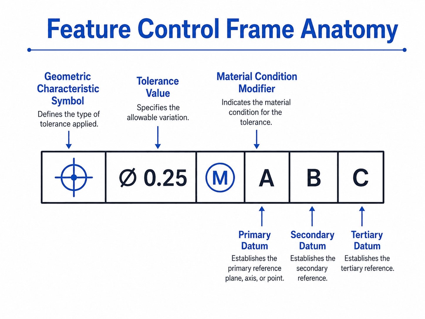
Read the frame from left to right: the symbol tells you what is controlled, the tolerance value tells you how much variation is allowed, the modifier changes how the tolerance behaves, and the datum letters define the inspection reference frame.
What Is GD&T?
GD&T is a standardized method for specifying geometric requirements on engineering drawings and digital product definitions. Instead of only saying that a dimension can vary by a plus/minus amount, GD&T defines the allowable variation of surfaces, axes, center planes, hole patterns, profiles, and other part features relative to functional references.
The practical purpose is to preserve design intent. A drawing may show the nominal size and location of a hole, but the design usually cares about whether a bolt fits, whether a bearing seat aligns, whether a sealing surface is flat enough, or whether an assembly can be inspected repeatably. GD&T provides a compact way to communicate those geometric requirements.
Good GD&T starts with function. The question is not “Which symbol can I add?” but “Which geometric variation would prevent this part from assembling, sealing, rotating, locating, or being inspected correctly?”
GD&T Symbols Quick Reference
GD&T symbols are grouped by the type of geometric variation they control. Some controls manage the shape of a single feature, while others define how a feature relates to datums, mating parts, or an inspection setup.
| Category | Common GD&T controls | What they control | Typical mechanical design use |
|---|---|---|---|
| Form | Straightness, flatness, circularity, cylindricity | The shape of an individual feature without requiring a datum reference. | Flat sealing faces, straight guide features, round turned diameters, and cylindrical bores. |
| Orientation | Parallelism, perpendicularity, angularity | The angular relationship between a feature and one or more datums. | Mounting faces, drilled holes, guide rails, machined shoulders, and bracket interfaces. |
| Location | Position, concentricity/coaxiality, symmetry | The allowable location variation of a feature relative to a datum reference frame. | Bolt holes, dowel holes, slots, locating pins, bores, and center planes. |
| Profile | Profile of a line, profile of a surface | The allowable boundary variation of a 2D line or 3D surface from the true profile. | Castings, molded parts, aerodynamic surfaces, contoured housings, and complex machined surfaces. |
| Runout | Circular runout, total runout | The variation observed as a feature rotates about a datum axis. | Shafts, hubs, bearing seats, pulleys, rotating flanges, and cylindrical assemblies. |
Some older drawings use concentricity and symmetry more often than modern practice usually requires. Depending on function, designers often use position, runout, or profile controls instead because they are usually easier to interpret, manufacture, and inspect consistently.
How to Read a GD&T Feature Control Frame
A feature control frame is read as a structured instruction. It does not only state a tolerance value; it tells the reader what feature is controlled, what geometric variation is allowed, which tolerance zone applies, and which datums establish the reference system.
Identify the controlled feature, read the geometric characteristic symbol, interpret the tolerance value and zone shape, check for MMC/LMC/RFS modifiers, read datum references in order, and confirm how the feature would be inspected.
| Reading step | What to check | Why it matters |
|---|---|---|
| 1. Controlled feature | Determine whether the frame applies to a hole, slot, surface, axis, center plane, pattern, or profile. | The feature type determines how the tolerance zone is interpreted. |
| 2. Geometric characteristic | Read the first symbol to identify position, flatness, profile, perpendicularity, runout, or another control. | The symbol defines the kind of variation being limited. |
| 3. Tolerance value and zone | Check the value and whether the zone is planar, cylindrical, parallel planes, profile boundary, or another shape. | A circular hole location often needs a cylindrical zone, not separate X and Y tolerance boxes. |
| 4. Material modifier | Look for MMC, LMC, or no modifier. No modifier usually means the stated geometric tolerance applies regardless of feature size. | Modifiers affect bonus tolerance, functional gauging, and worst-case assembly boundaries. |
| 5. Datum references | Read datum letters in order, such as A, B, C. | Datum order controls how the part is oriented and located during interpretation and inspection. |
| 6. Inspection method | Ask how the requirement would be checked by CMM, fixture, functional gauge, surface plate, or production inspection method. | A callout that cannot be measured repeatably will not protect quality in production. |
Why GD&T Is Used in Mechanical Design
Mechanical components are never manufactured perfectly. Every surface has some variation in size, flatness, location, orientation, and form. GD&T gives designers a way to control the variation that matters while allowing harmless variation where it does not affect function.
This matters because tight tolerances are expensive, but vague tolerances create scrap, rework, inspection disputes, and assembly problems. GD&T helps connect the design model to manufacturing and quality inspection by stating what must be controlled and what reference frame should be used to verify it.
| Mechanical design need | How GD&T helps | Typical example |
|---|---|---|
| Assembly fit | Controls the location and orientation of mating features relative to functional datums. | Bolt-hole pattern position relative to a mounting face and locating edge. |
| Repeatable inspection | Defines datums so the part is held and measured from the same references each time. | CMM inspection of a machined housing using primary, secondary, and tertiary datum features. |
| Functional surface control | Controls form, orientation, profile, or runout based on how the surface works in the assembly. | Flatness of a sealing face or runout of a rotating shaft diameter. |
| Cost control | Allows variation that does not affect function instead of forcing unnecessarily tight coordinate dimensions. | Using position tolerance on clearance holes instead of overly tight plus/minus X-Y dimensions. |
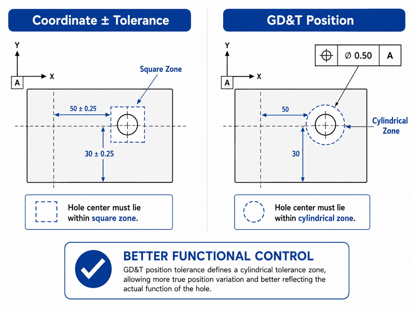
GD&T vs Plus/Minus Tolerancing
Plus/minus tolerancing is simple and useful for many size dimensions, but it can be weak when the functional requirement is geometric. A hole located by separate X and Y plus/minus dimensions creates a square tolerance region. A GD&T position callout can define a circular or cylindrical tolerance zone that better matches how round holes, pins, bolts, and gauges actually function.
The key difference is the shape and meaning of the allowed variation. Coordinate tolerancing controls separate dimensional directions, while GD&T can control the feature’s relationship to a datum reference frame.
When plus/minus tolerancing still makes sense
Plus/minus tolerancing is still appropriate for many simple size dimensions, stock lengths, non-critical clearances, and features where independent dimensional variation is acceptable. GD&T should not be added just to make a drawing look more advanced.
When GD&T is usually stronger
GD&T becomes more useful when the requirement depends on form, orientation, location, profile, runout, or a relationship to datums. Examples include shaft runout, perpendicularity of a mounting face, profile of a contoured surface, and true position of holes in a bolt pattern.
Which GD&T Control Should You Use?
The right GD&T control depends on the functional risk. Start by identifying how the part can fail: poor fit, leakage, misalignment, vibration, uneven wear, bad rotation, or inspection ambiguity. Then choose the control that targets that type of variation.
| Design problem | Likely GD&T control | Why it fits |
|---|---|---|
| A machined surface must seal against a gasket. | Flatness or profile of a surface | The functional risk is surface variation that can create leakage or uneven compression. |
| A bolt-hole pattern must accept fasteners without forcing assembly. | Position | The functional risk is hole location relative to the mounting datums and mating pattern. |
| A shaft or hub must rotate smoothly about an axis. | Circular runout or total runout | The functional risk is wobble, eccentric rotation, vibration, or uneven bearing loading. |
| A drilled hole must be square to a mounting face. | Perpendicularity | The functional risk is angular misalignment that affects fastener seating, pin fit, or assembly stack-up. |
| A molded or cast surface must stay within an envelope. | Profile of a surface | The functional risk is shape variation over a complex contour rather than one simple linear dimension. |
| A locating tab must remain centered between mating walls. | Position, profile, or symmetry depending on function | The control should match the way the tab is located and inspected, not just the fact that it appears centered on the drawing. |
Datums and the Datum Reference Frame
Datums are the reference system behind most useful GD&T callouts. A datum feature is the physical part feature identified on the drawing, such as a flat mounting face, bore, slot, or edge. A datum is the theoretically exact plane, axis, or point established from that physical feature for measurement and interpretation.
In the diagram below, notice how the part is progressively constrained by Datum A, Datum B, and Datum C. That sequence matters because it defines how the part is located before the controlled feature is evaluated.
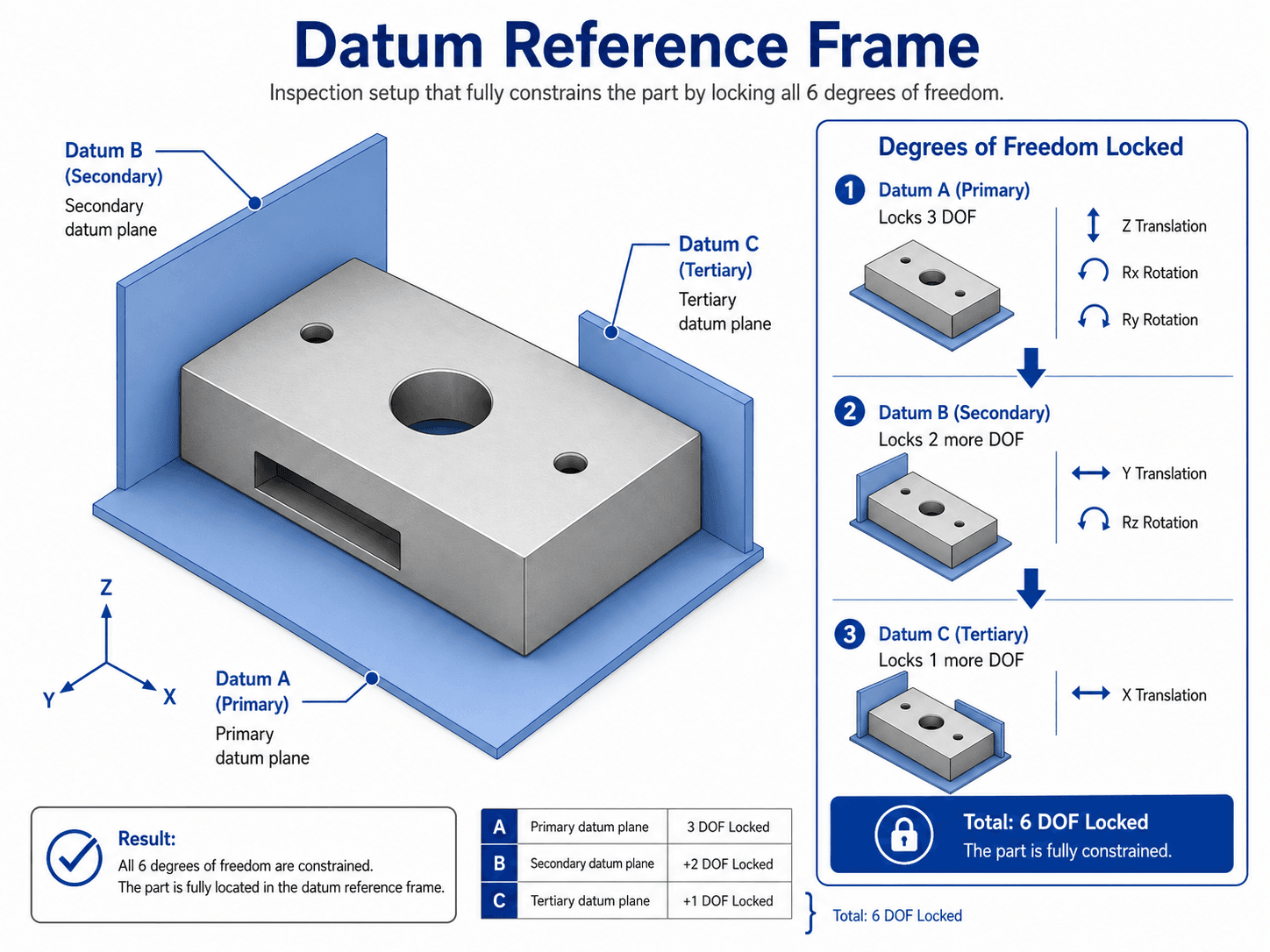
Primary, secondary, and tertiary datums
Datum order matters. The primary datum is contacted or established first and usually constrains the most important orientation. The secondary datum constrains additional movement, and the tertiary datum completes the setup. Changing the order can change the measured result, even if the same datum letters appear in the callout.
Choosing functional datums
The best datum features are usually the features that locate the part in the real assembly or inspection fixture. For a bracket, that may be a mounting face and two locating holes. For a rotating component, it may be a bearing diameter or central axis. Datum choices should not be based only on which surfaces are easy to see on the drawing.
True Position, Position Tolerance, MMC, and Bonus Tolerance
True position and position tolerance are related, but they are not the same thing. True position is the theoretically exact location of a feature. Position tolerance is the allowable tolerance zone around that exact location. For a round hole, that zone is commonly cylindrical.
MMC means maximum material condition. For an internal feature such as a hole, MMC is the smallest allowed hole size because that leaves the most material in the part. For an external feature such as a pin, MMC is the largest allowed size. When the MMC modifier is applied correctly, a feature can gain bonus tolerance as it departs from MMC.
| Term | Plain-language meaning | Why designers use it |
|---|---|---|
| Basic dimension | A theoretically exact dimension used to locate or orient a tolerance zone. | It defines the nominal target without adding plus/minus tolerance directly to that dimension. |
| True position | The theoretically exact location of a feature based on basic dimensions and datums. | It provides the nominal target location for holes, pins, slots, and patterns. |
| Position tolerance | The allowed zone around true position where the feature axis, center point, or center plane may vary. | It defines how much geometric location error is acceptable. |
| MMC | The feature size condition containing the maximum amount of material. | It supports functional gauging and can allow bonus tolerance when size variation improves assembly clearance. |
| RFS | Regardless of feature size; the geometric tolerance does not increase as feature size changes. | It is used when the geometric requirement should not loosen with size departure. |
| Virtual condition | The worst-case boundary combining size and geometric tolerance for assembly. | It helps determine whether mating parts or functional gauges will clear. |
Mini example: MMC bonus tolerance for a hole
Suppose a hole has a size tolerance of Ø0.500 to Ø0.510 and a position tolerance of Ø0.010 at MMC. For a hole, MMC is the smallest hole size, so MMC is Ø0.500. If the actual hole measures Ø0.506, the hole has departed from MMC by 0.006.
| Item | Value | Interpretation |
|---|---|---|
| Hole size range | Ø0.500 to Ø0.510 | The hole is allowed to vary within this size range. |
| MMC for the hole | Ø0.500 | The smallest allowed hole contains the maximum amount of material. |
| Stated position tolerance at MMC | Ø0.010 | This is the geometric tolerance available when the hole is at MMC. |
| Actual hole size | Ø0.506 | The actual hole is larger than MMC by 0.006. |
| Bonus tolerance | 0.006 | The extra clearance can be added to the position tolerance. |
| Total available position tolerance | Ø0.016 | Ø0.010 stated tolerance plus 0.006 bonus tolerance. |
MMC is powerful when the functional question is “Will this pin, bolt, or mating feature assemble?” It is not automatically correct for every location tolerance, especially where alignment, sealing, balance, or motion accuracy is more important than clearance.
Senior Engineer GD&T Drawing Review Checklist
A good GD&T review checks more than symbol placement. It asks whether the drawing communicates function, whether the datum scheme matches reality, and whether the requirement can be manufactured and inspected without guesswork.
Start with the assembly function, identify the features that locate or constrain the part, choose datums from those functional interfaces, apply geometric controls only where variation affects performance, then verify that the callouts can be inspected with available methods.
| GD&T review check | What to look for | Why it matters |
|---|---|---|
| Governing standard | The drawing clearly states the applicable GD&T standard or company drafting standard. | ASME and ISO-based practices are not always interpreted identically, so the standard prevents ambiguity. |
| Functional datum scheme | Datum A, B, and C correspond to surfaces, axes, or features that actually locate the part in the assembly or inspection setup. | Poor datum selection can make inspection repeatable but functionally meaningless. |
| Correct datum order | The primary datum constrains the most important orientation before secondary and tertiary references are applied. | Changing datum order can change the measured result and create drawing disputes. |
| Appropriate tolerance zone | The control creates the right zone shape: planar, cylindrical, parallel planes, profile boundary, or runout boundary. | The tolerance zone should match the way the feature fails or succeeds in the assembly. |
| Modifier intent | MMC, LMC, or RFS is used intentionally rather than copied from an older drawing. | Modifiers affect inspection, bonus tolerance, functional gauging, and assembly clearance. |
| Manufacturing capability | The tolerance is realistic for the process, material, machine setup, and production volume. | Unnecessarily tight GD&T increases cost and may create scrap without improving function. |
| Inspection method | The requirement can be verified by CMM, gauge, surface plate method, fixture, or agreed inspection process. | A tolerance that cannot be measured consistently will not protect quality in production. |
How Engineers Apply GD&T on Real Drawings
GD&T should be applied after the designer understands the part’s function, mating interfaces, manufacturing process, and inspection strategy. The strongest drawings usually control a small number of function-critical features very clearly rather than applying complex symbols everywhere.
- Mounting plates: use flatness, perpendicularity, or position to control how the plate seats and how fasteners align.
- Machined housings: use datums from mounting faces and bores so bearing seats, shafts, covers, and bolt patterns align.
- Rotating parts: use runout or position controls to manage wobble, vibration, bearing fit, and concentricity-related issues.
- Molded or cast parts: use profile tolerance when complex surfaces need a boundary rather than many local plus/minus dimensions.
Design sequence that works
First define what the part must do. Next identify how it is located in the assembly. Then choose datum features from that functional setup. After that, select geometric controls for the features that actually affect fit, function, movement, sealing, or inspection. Finally, review the drawing with manufacturing and quality before release.
If the drawing has a GD&T callout, ask: “What bad part would this reject, and what good part would this allow?” If that question is hard to answer, the callout may not be tied closely enough to function.
What GD&T Does Not Do
GD&T improves the way geometry is specified, but it does not automatically make a part manufacturable, inexpensive, or easy to inspect. It is a communication system, not a substitute for process capability, tolerance analysis, supplier feedback, or design validation.
| GD&T does not automatically… | Why | Engineering action |
|---|---|---|
| Reduce part cost | Overly tight or unnecessary controls can increase machining and inspection effort. | Apply GD&T only where it protects function or clarifies inspection. |
| Guarantee manufacturability | The drawing may specify geometry that is difficult for the selected process or fixture setup. | Review tolerances with manufacturing before release. |
| Replace tolerance stack-up review | Individual feature controls do not automatically prove the full assembly will work. | Review critical assemblies, interfaces, clearances, and worst-case boundaries. |
| Resolve vague design intent | A symbol cannot fix unclear functional requirements. | Define the function first, then choose the GD&T control. |
Engineering Judgment and Field Reality
In real design work, GD&T lives between the ideal CAD model and the physical production floor. CAD geometry is perfect, but machined, molded, cast, welded, and printed parts are not. Tool deflection, fixture repeatability, thermal effects, casting variation, burrs, surface finish, and inspection setup can all influence whether a GD&T requirement is practical.
The best GD&T is usually developed with manufacturing and inspection input. A designer may intend to control a feature from a datum face, but the machinist may create the feature in a different setup, and the inspector may measure it with a different fixturing sequence. When those assumptions conflict, the drawing can become a source of cost and rework instead of clarity.
A tolerance that looks reasonable in CAD can be expensive in production if it requires extra setups, special fixtures, slow inspection, or a tighter process than the part function actually needs.
When This Breaks Down
GD&T breaks down when symbols are added without a functional reason, when the datum scheme does not represent the assembly or inspection setup, or when the specified tolerance cannot be verified consistently. The problem is usually not the GD&T language itself; it is the mismatch between the drawing, the manufacturing process, and the intended function.
- Wrong datum features: the part is measured from surfaces that do not control how it works in the assembly.
- Overcontrolled geometry: non-critical surfaces receive tight controls that add machining and inspection cost.
- Unclear inspection setup: quality teams cannot reproduce the datum reference frame consistently.
- Misused modifiers: MMC or LMC is applied without understanding bonus tolerance, virtual condition, or functional gauging.
- Mixed standard assumptions: teams interpret the same callout differently because the drawing does not clearly define the governing practice.
Common GD&T Mistakes and Practical Checks
Many GD&T errors come from treating symbols as drafting decoration instead of engineering requirements. A clear drawing should make the feature requirement easier to understand, not harder.
| Common mistake | Why it causes problems | Practical check |
|---|---|---|
| Adding GD&T to every feature | It increases drawing complexity and may create unnecessary inspection burden. | Control only features where geometric variation affects function, assembly, inspection, or reliability. |
| Using datums that are easy to draw instead of functional | The part may pass inspection but fail to assemble or perform correctly. | Trace how the part contacts mating components and how it is constrained in service. |
| Confusing size tolerance with position tolerance | A hole can be the correct diameter but still be in the wrong location. | Control size separately from location when both affect function. |
| Copying MMC from a similar part | Bonus tolerance may be inappropriate for alignment-sensitive or motion-critical features. | Use MMC when clearance or functional gauging is the controlling concern. |
| Ignoring inspection capability | The requirement may be theoretically correct but difficult to verify consistently. | Review the callout with quality before release, especially for tight or complex controls. |
The most expensive GD&T mistake is a callout that appears precise but does not match part function. It can drive cost, create inspection disputes, and still fail to protect the assembly.
GD&T Standards and Design References
GD&T should be interpreted through the governing standard or company drafting practice stated on the drawing. In U.S.-based mechanical design, ASME Y14.5 is the main reference family for geometric dimensioning and tolerancing language. ISO GPS standards use related concepts, but ASME and ISO interpretations are not always interchangeable.
- ASME Y14.5: ASME Y14.5 Dimensioning and Tolerancing standard describes the symbols, rules, definitions, requirements, defaults, and recommended practices used for stating and interpreting GD&T on drawings, digital product definitions, and related documents.
- Project-specific criteria: company drafting standards, customer requirements, inspection plans, supplier agreements, and industry practices may add requirements for how GD&T is applied and documented.
- Engineering use: designers use the standard for drawing language, but final callout choices still require engineering judgment about part function, manufacturability, inspection, and cost.
Frequently Asked Questions
GD&T stands for Geometric Dimensioning and Tolerancing. It is a symbolic engineering drawing language used to define allowable variation in part geometry, including form, orientation, location, profile, and runout.
GD&T is often better when a feature must function relative to datums, mating parts, or an assembly condition. It can define tolerance zones that better match function, such as a cylindrical position tolerance zone for a hole instead of a square coordinate tolerance box.
A feature control frame is the rectangular GD&T callout that tells the reader which geometric characteristic is controlled, how much variation is allowed, whether a modifier applies, and which datums establish the reference frame.
Datums are theoretically exact references established from physical datum features on a part. They create the coordinate reference frame used to orient, locate, and inspect controlled features.
MMC means maximum material condition. For a hole, it is the smallest allowed hole size; for a pin or shaft, it is the largest allowed outside size. When used correctly, MMC can allow bonus tolerance as the actual feature departs from maximum material condition.
Summary and Next Steps
GD&T is a mechanical design language for controlling real geometric variation in manufactured parts. It helps designers communicate how features must relate to datums, tolerance zones, mating parts, and inspection setups so that drawings protect function instead of simply listing dimensions.
The most important GD&T decisions are the feature control frame, datum reference frame, tolerance zone, material modifier, and inspection method. A strong drawing uses these tools selectively and ties each callout to assembly fit, motion, sealing, alignment, reliability, or quality control.
Where to go next
Continue your learning path with related Turn2Engineering resources.
-
Mechanical Design
Explore mechanical design concepts that connect part function, manufacturing, analysis, and drawing requirements.
-
Engineering Calculators
Use engineering calculators for related design, mechanics, and analysis workflows.
-
Engineering Equations
Review engineering equation references that support design calculations and technical analysis.