
Direct Answer
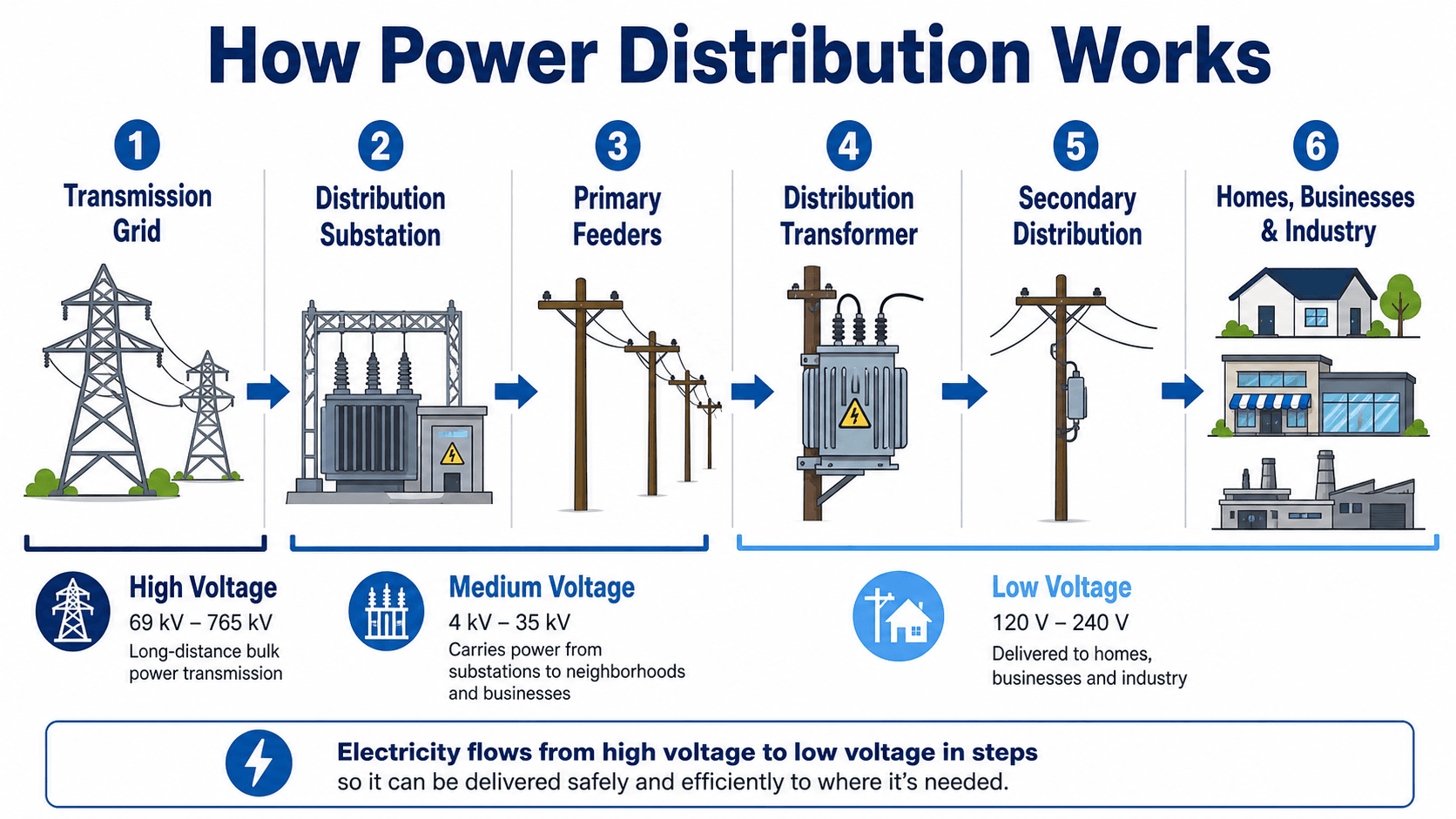
Power distribution is the local-delivery portion of the electric grid. It carries electricity from distribution substations through primary feeders and laterals, steps voltage down through distribution transformers, and delivers usable voltage to homes, businesses, and industrial facilities through secondary circuits and service conductors.
A distribution system must do more than carry load. Engineers also manage voltage, losses, fault current, protective-device coordination, switching, phase balance, restoration, power quality, load growth, and distributed energy resources such as rooftop solar, batteries, and EV charging.
How Power Distribution Works From Substation to Customer
The distribution path begins where the bulk grid is stepped down to a local feeder voltage and ends at the customer service connection.
A distribution substation receives power from the transmission or subtransmission system and supplies one or more medium-voltage feeders.
Primary feeders, laterals, switches, reclosers, regulators, capacitor banks, and distribution transformers move and condition power locally.
Secondary circuits and service conductors deliver usable voltage to residential, commercial, and industrial loads.
Distribution Substation
The distribution substation is the source point for local feeders. It typically contains transformers, buses, breakers, protective relays, CTs and VTs, voltage-control equipment, station batteries, and SCADA or automation systems. The substation establishes feeder voltage, protection zones, source capacity, and switching flexibility for the local service area.
Primary Feeder and Laterals
A primary feeder carries medium-voltage power away from the substation. Main trunks are often three-phase, while laterals may be single-phase or three-phase depending on the load served. Reclosers, fuses, switches, regulators, and capacitor banks are placed along the feeder to improve protection, voltage performance, and restoration capability.
Distribution Transformer and Secondary Service
Distribution transformers step primary voltage down to customer utilization voltage. Secondary conductors then supply service drops or underground service laterals. Keeping low-voltage secondary runs relatively short helps limit current, voltage drop, conductor size, and losses.
The U.S. Energy Information Administration describes the grid as a system of substations, transformers, and power lines, with lower-voltage distribution lines delivering electricity locally to customers after voltage is reduced: EIA — Delivery to Consumers.
Main Components of a Power Distribution System
Distribution systems combine source equipment, feeders, transformers, switching, protection, voltage control, metering, and communications so local loads can be served safely and reliably.
| Component | Main function | Important engineering checks |
|---|---|---|
| Distribution substation | Steps voltage down and supplies local feeders | Transformer MVA, bus rating, breaker duty, protection, voltage control, source redundancy |
| Primary feeder | Carries medium-voltage power through the service area | Ampacity, voltage drop, phase balance, losses, protection, loading, future growth |
| Lateral | Branches from the feeder to serve smaller load groups | Conductor rating, fuse/recloser coordination, phase loading, restoration path |
| Distribution transformer | Steps primary voltage down to customer utilization voltage | kVA, load diversity, thermal loading, impedance, service voltage, efficiency, access |
| Recloser | Interrupts faults and automatically recloses for temporary disturbances | Pickup, timing, shot sequence, coordination, fault level, communications |
| Fuse cutout | Protects laterals or transformers and isolates localized faults | Fuse curve, transformer protection, upstream coordination, fault current |
| Voltage regulator / LTC | Adjusts voltage as load and feeder conditions change | Setpoint, bandwidth, line-drop compensation, reverse power, control coordination |
| Capacitor bank | Supplies reactive power and supports voltage or power factor | kVAR, switching strategy, harmonics, resonance, overvoltage, protection |
| Switch / tie point | Sections the feeder and enables maintenance or load transfer | Rating, normal-open/closed status, restoration loading, interlocks, automation |
| Metering / SCADA / sensors | Measures load, voltage, events, status, and system operation | Accuracy, communications, cybersecurity, time synchronization, data quality |
Swipe horizontally to view all table columns.
For the broader system relationship between these devices and upstream transmission equipment, see Power System Components.
Primary vs. Secondary Power Distribution
Primary distribution is the medium-voltage network between the substation and local distribution transformers; secondary distribution is the lower-voltage network between those transformers and customer service equipment.
Primary Distribution
Medium-voltage feeders and laterals carry power efficiently across a local service territory. Common equipment includes reclosers, fuses, switches, voltage regulators, capacitor banks, and distribution transformers.
Secondary Distribution
Low-voltage conductors connect distribution transformers to customer services. Residential, commercial, and industrial service voltages vary by utility and application.
Customer Service
The utility/customer ownership boundary may occur at the meter, service point, transformer, or another defined location depending on the utility and service arrangement.
Typical Voltage Levels
Exact voltage classifications vary by utility, country, system age, and service type. In North America, primary distribution commonly uses medium-voltage classes such as 4.16 kV, 12.47 kV, 13.2 kV, 13.8 kV, 24.9 kV, or 34.5 kV. Common secondary services include 120/240 V split-phase, 208Y/120 V, and 480Y/277 V. These are examples, not universal limits.
Long low-voltage runs create high current, larger conductors, higher voltage drop, and greater losses. That is why utilities generally keep power at medium voltage until relatively close to the customer.
DOE’s current distribution-transformer definition under 10 CFR 431.192 covers certain transformers with input voltage of 34.5 kV or less and output voltage of 600 V or less, subject to the detailed regulatory definition and exclusions: DOE — Distribution Transformers.
Radial, Loop, and Network Distribution Systems
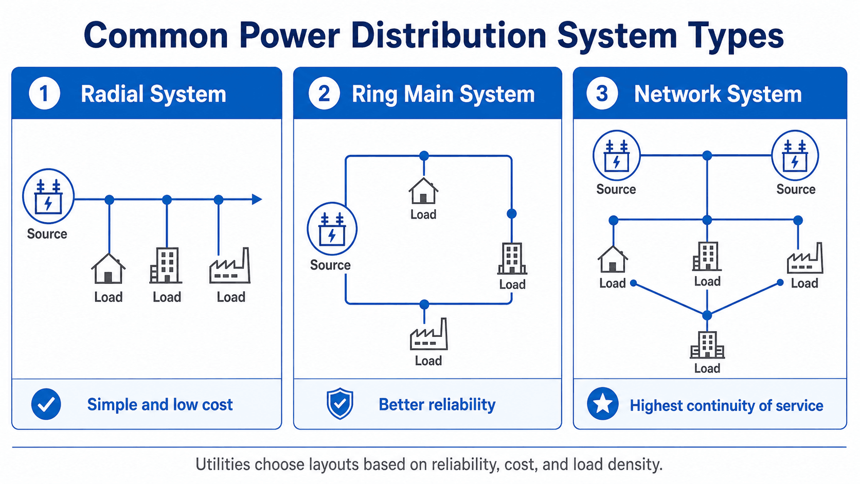
Distribution topology determines how many alternate paths exist between the source and the load, which directly affects cost, protection complexity, switching flexibility, and service continuity.
| Topology | Best fit | Primary advantage | Main tradeoff |
|---|---|---|---|
| Radial | Residential, rural, and lower-density systems | Simple, economical, straightforward protection | Single upstream faults can interrupt all downstream loads |
| Loop / ring main | Suburban, campus, commercial, and underground systems | Alternate source path and better restoration flexibility | More switches, more operating complexity, protection considerations |
| Parallel feeders | Large or critical loads requiring redundancy | Multiple supply paths and increased service continuity | Higher cost and more complex coordination and loading |
| Secondary network | Dense urban districts and very high-reliability load areas | High continuity through multiple interconnected sources | Specialized network protectors, higher cost, greater complexity |
Swipe horizontally to view all table columns.
Overhead vs. Underground Distribution
Overhead systems are generally easier to inspect, repair, expand, and build at lower initial cost, but they are more exposed to wind, vegetation, lightning, ice, vehicles, and wildlife. Underground systems reduce many overhead exposures and visual impacts but usually cost more to install and can take longer to fault-locate and repair.
Voltage Drop, Volt-VAR Control, and Power Quality
Distribution feeders must maintain usable voltage as load, power factor, feeder length, conductor impedance, transformer taps, capacitor status, and distributed generation change throughout the day.
Simplified Voltage-Drop Relationship
- ΔV Approximate voltage change along the modeled circuit section.
- I Load current through the circuit section.
- R Effective circuit resistance for the modeled section.
- X Effective circuit reactance for the modeled section.
- φ Load power-factor angle.
This is a simplified instructional relationship, not a substitute for a full unbalanced three-phase feeder model. Real distribution studies may need phase-specific loads, transformer models, regulators, capacitors, DER, service transformers, line sections, and time-varying conditions.
Volt-VAR Control
Voltage regulators, transformer load-tap changers, capacitor banks, and smart inverters can influence feeder voltage and reactive power. Their settings must be coordinated so one device does not repeatedly counteract another or create excessive switching.
Power Quality
Distribution power quality can include voltage sags, swells, flicker, phase unbalance, interruptions, and harmonics. Large motors, variable-frequency drives, nonlinear loads, capacitor switching, EV chargers, and inverter-based resources can all affect local power quality.
Distribution Losses
Engineering meaning: High current, long feeders, poor power factor, unbalanced phase loading, and overloaded equipment can all increase losses or voltage problems. Higher primary distribution voltage can reduce current for the same transferred power, but system voltage selection is a broader utility-planning decision.
Distribution Protection, Switching, and Reliability
Distribution protection aims to isolate the smallest practical faulted section while keeping unaffected customers energized and allowing service to be restored safely.
-
Detect the abnormal condition.
Feeder relays, reclosers, fuses, or other protective devices respond to fault current, voltage conditions, or programmed logic.
-
Isolate the faulted section.
The protection scheme should clear the fault with the smallest reasonable customer interruption consistent with equipment protection and safety.
-
Determine whether the fault is temporary or permanent.
Reclosers can restore service after temporary faults; permanent faults require isolation and repair before the affected section is re-energized.
-
Restore unaffected load.
Tie switches, alternate feeders, automated switching, or manual sectionalizing may allow healthy sections to be back-fed within equipment and voltage limits.
| Device | Typical role | Key coordination issue |
|---|---|---|
| Substation feeder breaker | Protects and switches the feeder source | Must coordinate with downstream reclosers and fuses while providing backup protection |
| Recloser | Clears temporary faults and can automatically restore service | Pickup, curve, fast/slow operations, lockout, downstream fuse coordination |
| Fuse | Isolates laterals, transformers, or localized faults | Must operate selectively relative to upstream reclosers and breakers |
| Sectionalizer | Opens during an upstream de-energized interval after counting fault operations | Sequence must coordinate with upstream recloser operation |
| Tie switch | Transfers healthy load to an alternate feeder or source | Alternate path must have acceptable loading, voltage, protection, and operating status |
Swipe horizontally to view all table columns.
A stronger feeder is not automatically a more reliable feeder. Reliability also depends on sectionalizing, protection selectivity, alternate source paths, automation, vegetation exposure, equipment condition, restoration access, and operating procedures.
How Engineers Plan and Review Distribution Systems
Distribution planning connects load forecasts and physical feeder layouts to electrical models so utilities can determine when new transformers, feeders, conductor upgrades, voltage-control equipment, switching, or substations are needed.
Peak demand, hourly shape, seasonal variation, EV charging, electrification, distributed generation, future development, and large new customers.
Normal and contingency loading, end-of-line voltage, phase balance, losses, transformer loading, and thermal limits.
Available fault current, fuse/recloser/breaker coordination, DER impact, transformer protection, and switching configuration.
Outage exposure, tie points, restoration paths, automation, vegetation, underground cable risk, critical loads, and equipment condition.
| Study / check | Question answered | Typical outputs |
|---|---|---|
| Load flow / feeder model | Are feeder voltage and equipment loading acceptable? | Phase voltage, current, transformer loading, losses, regulator/capacitor operation |
| Short-circuit study | What fault current is available throughout the feeder? | Fault current, equipment duty, protection sensitivity |
| Protection coordination | Will breakers, reclosers, and fuses operate selectively? | Pickup settings, time-current coordination, fuse-saving or fuse-blowing behavior |
| Voltage / Volt-VAR study | Can voltage stay acceptable as load and DER vary? | Voltage profile, regulator taps, capacitor switching, inverter reactive-power needs |
| Hosting-capacity / DER study | How much DER can connect before constraints require mitigation? | Voltage rise, thermal constraints, protection impacts, reverse flow, upgrade triggers |
| Reliability / restoration review | How can healthy load be restored after faults or planned outages? | Switching plans, alternate feed capacity, critical customer exposure, sectionalizing needs |
Swipe horizontally to view all table columns.
DOE’s Distribution Grid Transformation program identifies integrated distribution system planning, distributed resource utilization, and future distribution-system design as key areas because DER, policy changes, customer behavior, and electrification are increasing distribution-grid complexity: DOE — Distribution Grid Transformation.
How DER, EVs, Automation, and Electrification Are Changing Distribution
Modern distribution systems increasingly operate as active networks rather than one-way delivery circuits because rooftop solar, batteries, EV charging, smart inverters, automated switches, demand response, and large new loads can change both power flow and operating requirements.
Distributed Energy Resources
Solar PV, batteries, generators, and other distributed resources can reduce net load or export power back toward the substation. Reverse flow can change regulator behavior, transformer loading, voltage profiles, fault-current contribution, and the assumptions behind older protection schemes.
EV Charging and Electrification
Electric vehicles, heat pumps, industrial electrification, and new data or computing loads can create rapid local load growth. The limiting asset may be a service transformer, lateral, feeder trunk, substation transformer, or upstream source rather than the customer equipment itself.
Distribution Automation
SCADA, feeder sensors, smart meters, automated switches, fault indicators, advanced distribution management systems, and coordinated Volt-VAR controls can improve visibility and restoration. Automation is valuable only when the underlying equipment ratings, protection logic, communications, cybersecurity, and operating procedures are sound.
DOE states that full utilization of distributed energy resources requires advances in how the distribution grid is planned, operated, and designed, and identifies integrated planning and coordinated DER utilization as major areas of current grid transformation: DOE — Distribution Grid Transformation.
DOE also identifies distribution transformers as critical grid components and continues to address transformer supply-chain constraints and long lead times: DOE — Distribution Transformers.
Distribution bottlenecks are often local. A system may have adequate generation and transmission capacity while one feeder, transformer, switch, underground cable section, or substation transformer limits a new customer or DER connection.
Power Distribution Engineering References
These sources support the page’s grid-delivery, distribution-transformer, modernization, DER, and planning context. Final distribution design still depends on current utility standards, service manuals, equipment data, interconnection rules, local codes, and project-specific studies.
- U.S. Energy Information Administration — Delivery to Consumers Transmission/distribution relationship, substations, transformers, and local electricity delivery.
- U.S. Department of Energy — Distribution Grid Transformation Integrated distribution planning, distributed-resource utilization, and changing distribution-system design.
- U.S. Department of Energy — Distribution Transformers Federal distribution-transformer definition and current DOE efficiency-standard context.
- U.S. Department of Energy — Distribution Transformers Distribution-transformer supply-chain and availability context.
- U.S. Department of Energy — Grid Systems and Components Grid modernization and next-generation electricity-delivery hardware/software context.
Frequently Asked Questions
What is power distribution in electrical engineering?
Power distribution is the local portion of the electric grid that delivers electricity from distribution substations to end users through feeders, laterals, distribution transformers, secondary circuits, service conductors, switching, protection, and metering equipment.
What is the difference between power transmission and power distribution?
Transmission moves bulk power through the high-voltage backbone between generation, major substations, and load regions. Distribution delivers power locally at medium and low voltage from substations to customers.
What is a distribution feeder?
A distribution feeder is a medium-voltage circuit leaving a distribution substation and serving a local area. It may include main trunks, laterals, reclosers, switches, fuses, regulators, capacitor banks, and distribution transformers.
What are primary and secondary distribution?
Primary distribution is the medium-voltage portion between the substation and local distribution transformers. Secondary distribution is the lower-voltage portion from those transformers to customer service equipment.
What are the main types of distribution systems?
Common distribution topologies include radial systems, loop or ring-main systems, parallel feeders, and secondary networks. The topology affects cost, protection complexity, switching flexibility, and service continuity.
How does rooftop solar affect a distribution feeder?
Rooftop solar can reduce local net load or export power upstream. Higher DER penetration can affect voltage, regulator and capacitor operation, transformer loading, reverse power flow, protection sensitivity, and the amount of additional generation the feeder can accommodate without upgrades.
Summary and Next Step
Power distribution is the local-delivery system that connects substations to customers through feeders, laterals, transformers, service conductors, switching, protection, voltage-control equipment, and monitoring systems.
Strong distribution engineering balances capacity, voltage, losses, fault current, protection coordination, restoration flexibility, phase balance, power quality, asset condition, load growth, and DER. The controlling constraint may be electrical, operational, or physical—and it can change as the feeder evolves.