
Direct Answer
Power generation is the conversion of primary energy—such as natural gas, nuclear heat, flowing water, wind, sunlight, geothermal heat, or stored energy—into electrical power. Most large power plants use a turbine or engine to turn a generator, while solar photovoltaic systems and batteries connect through power electronics and inverters.
For the grid, producing electricity is only the first requirement. A generation resource must also operate within voltage and frequency limits, satisfy protection and interconnection requirements, provide the required real and reactive power behavior, and produce power when and where the system needs it.
Main Power Generation Methods and What They Do
Start by separating the energy source from the electrical conversion technology. Different fuels and natural resources can use similar rotating equipment, while solar PV produces electricity without a turbine-generator set.
Fuel, nuclear heat, water, wind, sunlight, geothermal heat, biomass, or stored electrical energy.
Turbine, engine, synchronous generator, induction generator, PV module, converter, or inverter.
Energy production, peak capacity, load following, reserve, voltage support, local resilience, or variable renewable output.
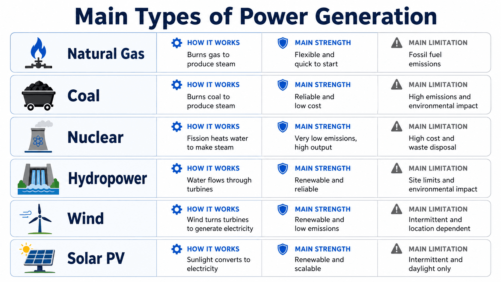
| Generation type | How electricity is produced | Typical operating role | Important engineering limitation |
|---|---|---|---|
| Natural gas | Gas turbine, steam turbine, combined cycle, or reciprocating engine drives a generator | Baseload, intermediate, load following, peaking, reserve | Fuel availability and price, emissions, ambient derating, ramp/start constraints |
| Coal | Fuel heat produces steam that drives a turbine-generator | Historically steady thermal generation | Emissions controls, slower cycling, fuel handling, water and environmental requirements |
| Nuclear | Fission heat produces steam that drives a turbine-generator | High-capacity, high-capacity-factor generation | Capital intensity, licensing, cooling, refueling outages, safety systems |
| Hydropower | Moving or falling water turns a hydraulic turbine-generator | Energy, peaking, regulation, reserve where reservoir control exists | Hydrology, reservoir constraints, geography, environmental requirements |
| Wind | Wind turbine rotor drives a generator through direct-drive or geared equipment with power electronics | Variable renewable generation | Wind availability, interconnection strength, controls, transmission availability |
| Solar PV | PV modules convert sunlight directly to DC; inverters convert and control AC output | Variable renewable generation | Solar resource, weather, curtailment, inverter controls, interconnection capability |
| Geothermal | Geothermal heat drives steam or binary-cycle generation equipment | Steady renewable generation where resources are suitable | Location, drilling, reservoir performance, corrosion/scaling |
| Battery energy storage | Stored DC energy is converted through a bidirectional inverter | Fast response, reserve, peak shifting, grid services | Energy duration, state of charge, degradation, controls, charging source |
Swipe horizontally to view all table columns.
Nameplate MW alone is not enough to compare generation resources. Engineers also evaluate annual MWh, dependable capacity, dispatchability, ramp rate, minimum output, outage risk, reactive capability, fault behavior, interconnection limits, fuel or resource availability, and where the plant connects.
How Electricity Is Produced From Energy Sources
Most utility-scale electricity is produced by either rotating an electromagnetic generator with a turbine or engine, or by converting DC electricity from PV modules, batteries, or other DC sources through power electronics.
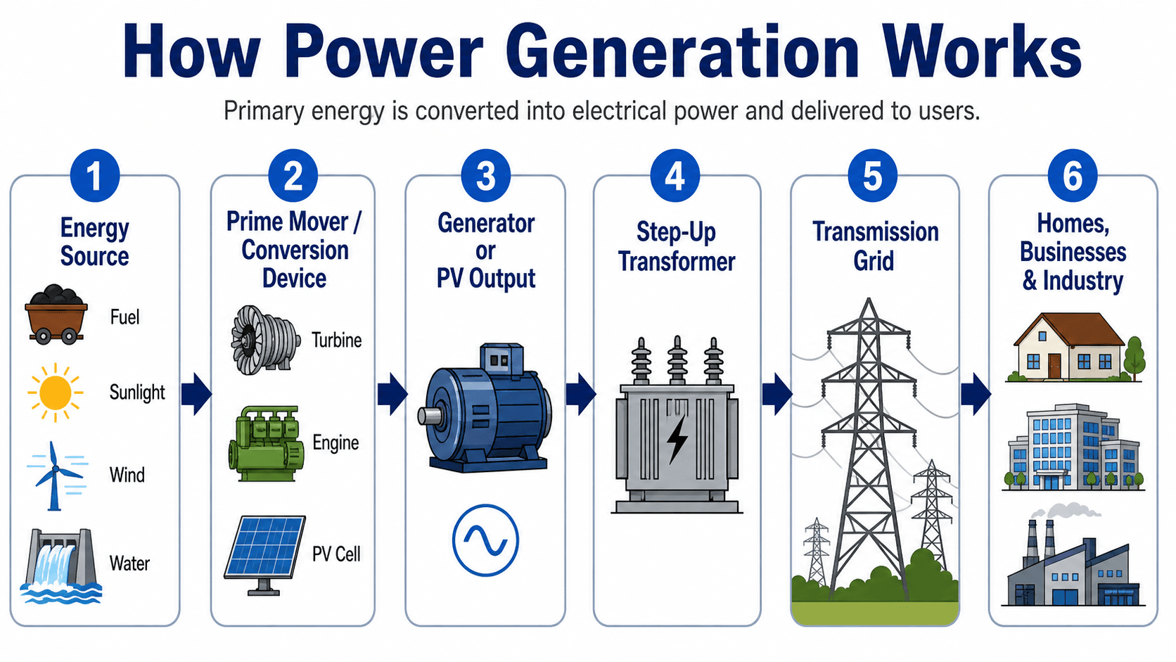
Thermal Generation
Natural-gas steam plants, coal plants, nuclear plants, biomass plants, and some geothermal plants first convert primary energy into heat. Steam or hot combustion gas then expands through a turbine. The turbine shaft turns the generator rotor, producing electrical output at the generator terminals.
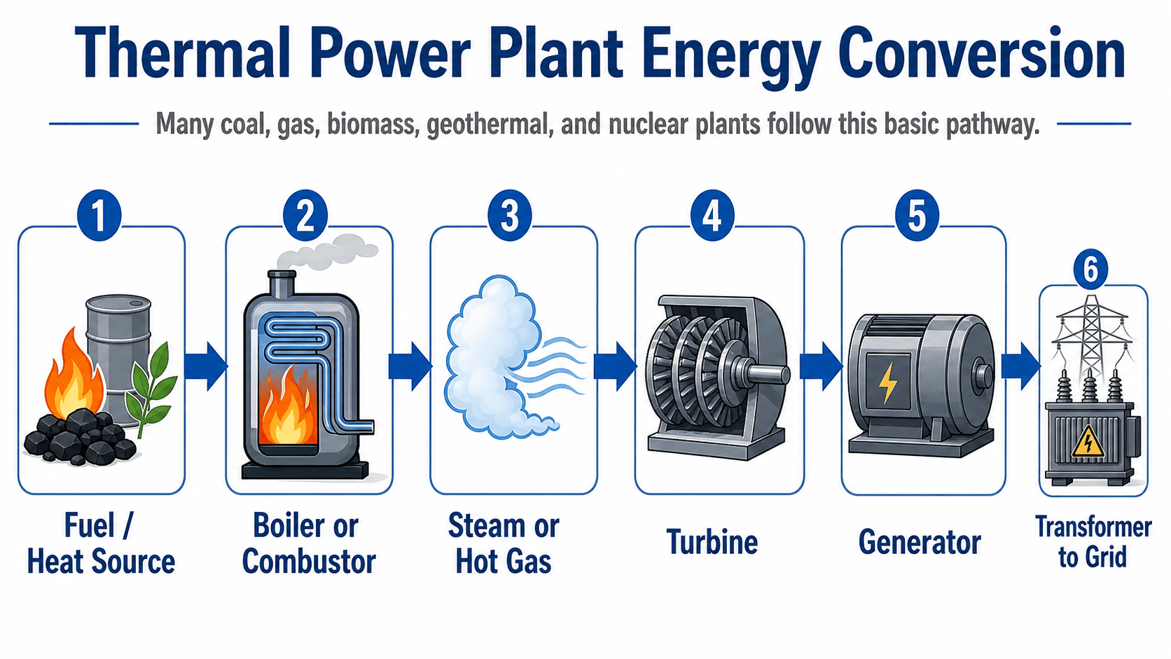
Hydro and Wind Generation
Hydropower and wind bypass the fuel-to-heat step. Water or air directly supplies mechanical energy to a turbine rotor. Depending on the machine, the generator may be synchronous, induction-based, or connected through partial or full power converters.
Solar Photovoltaic Generation
Solar PV does not require a turbine. PV cells convert solar radiation directly into DC electricity. Inverters then regulate the DC input and produce controlled AC output for a facility or electric grid. Plant-level controls, protection, transformers, and collection systems are still required for utility-scale installations.
The U.S. Energy Information Administration describes electricity as a secondary energy source produced by converting primary energy sources and explains that most electricity generation uses electromagnetic generators driven by mechanical prime movers: EIA — Electricity Explained and EIA — How Electricity Is Generated.
How Generators and Inverters Connect to the Grid
A generation resource must do more than produce watts: its electrical output must be transformed, switched, protected, measured, controlled, and coordinated with the power system at the point of interconnection.
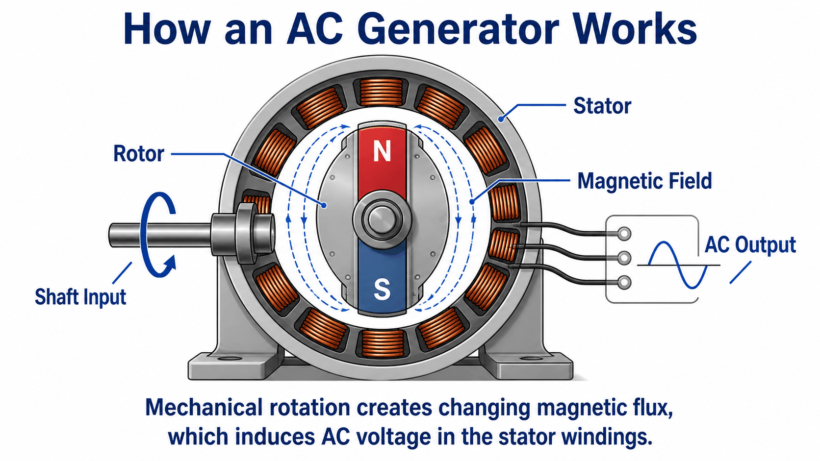
How an AC Generator Works
In a simplified synchronous generator, mechanical torque rotates the rotor magnetic field relative to stator windings. Changing magnetic flux induces three-phase voltage in the stator. Excitation controls the machine’s magnetic field and affects terminal voltage and reactive-power capability.
Synchronization and Frequency
Before a synchronous generator is connected to an energized AC system, its voltage magnitude, frequency, phase sequence, and phase-angle relationship must be suitable for synchronization. Once connected to a large grid, mechanical input primarily affects real-power output, while excitation strongly influences reactive-power output and terminal voltage within the machine’s operating limits.
Transformer, Switchgear, and Protection
Generator step-up transformers raise generator terminal voltage to the plant interconnection voltage. Circuit breakers and disconnectors provide switching and isolation. CTs and VTs provide measurements to relays, meters, synchronizing systems, and controls. Protection systems must detect generator, transformer, bus, line, and abnormal operating conditions without unnecessary trips.
Inverter-Based Resources
Solar PV, batteries, and many modern wind plants rely on inverter controls rather than the electromechanical behavior of a synchronous machine. Their voltage response, reactive current, fault ride-through, frequency response, and dynamic behavior depend heavily on controls, protection settings, plant controllers, and the strength of the connected grid.
NERC has identified modeling, ride-through, and dynamic-performance issues as important reliability considerations for bulk-power-system-connected inverter-based resources: NERC — 2025 State of Reliability Overview and NERC — Inverter-Based Resource Model Quality Findings.
Renewable vs. Nonrenewable and Rotating vs. Inverter-Based Generation
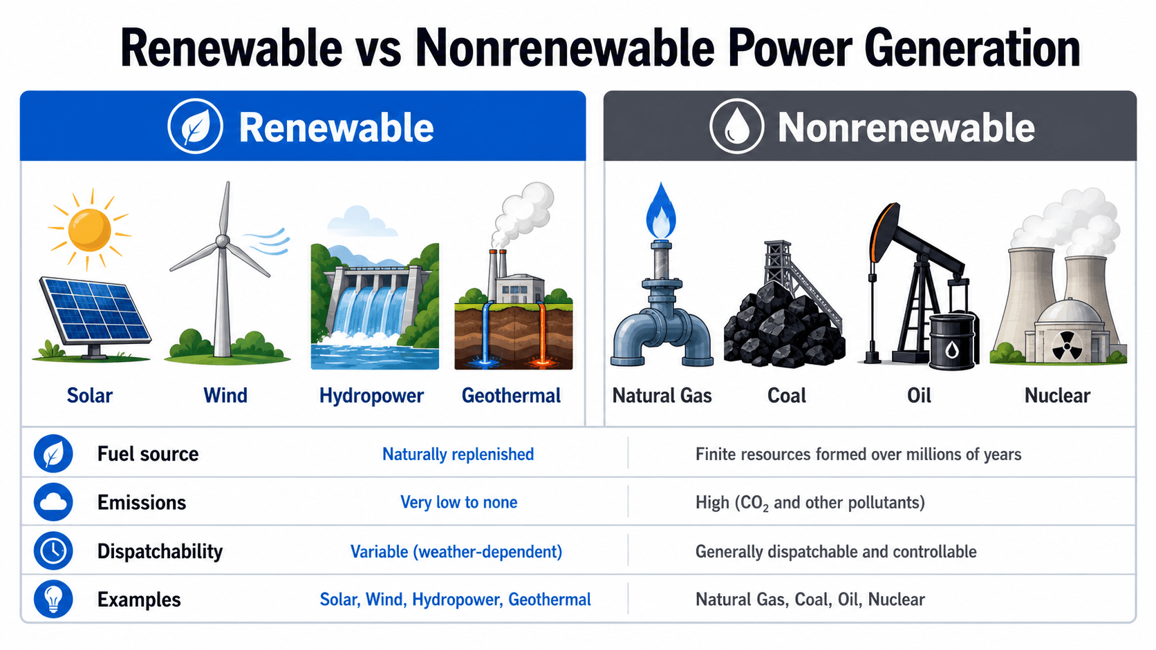
Renewable/nonrenewable describes the primary energy resource, while synchronous/inverter-based describes important electrical behavior. These classifications answer different engineering questions and should not be treated as interchangeable.
Renewable Generation
Includes wind, solar, hydropower, geothermal, and qualifying biomass resources. Output may be variable or dispatchable depending on the resource and storage available.
Nonrenewable Generation
Includes fossil-fuel and nuclear generation. Nuclear is nonrenewable because its fuel is mined, but it is not fossil-fuel generation.
Electrical Interface
Synchronous generators and inverter-based resources can provide different fault-current, voltage-control, frequency-response, and dynamic characteristics even when their MW ratings are similar.
Do not assume renewable means inverter-based or nonrenewable means synchronous. Hydroelectric and geothermal plants can use synchronous generators; batteries and solar PV are typically inverter-based; modern wind turbine electrical interfaces vary by design.
Power, Energy, Capacity, and Capacity Factor
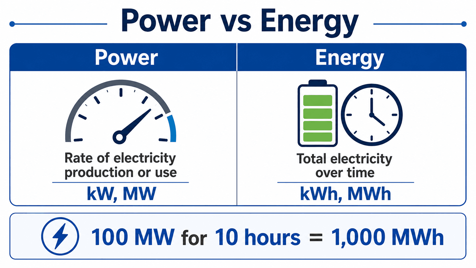
Power is the instantaneous rate of electrical energy production, while energy is power accumulated over time. Capacity is the maximum rated output under specified conditions. Capacity factor compares actual generation over a period with the energy that would have been produced at full rated output for that entire period.
Energy From Constant Power
- E Electrical energy; commonly kWh, MWh, or GWh.
- P Electrical power output; commonly kW or MW.
- t Time over which the power is produced; commonly hours.
Capacity Factor
Engineering meaning: Two 100 MW resources can have identical nameplate capacity yet produce very different annual energy and provide different levels of dependable capacity. Capacity factor helps quantify utilization, but it does not by itself measure reliability contribution or dispatchability.
Worked Example: 250 MW Plant Annual Capacity Factor
A 250 MW generating plant produces 1,642,500 MWh over a 365-day year. Determine its annual capacity factor.
Calculate maximum possible annual energy
Multiply rated capacity by the number of hours in the year.
Divide actual energy by maximum possible energy
The ratio gives the average utilization of the plant’s rated output over the year.
Average output is 75% of 250 MW, or 187.5 MW.
Capacity factor does not reveal when the energy was produced or whether the plant was available during peak system demand.
Compare capacity factor with availability, forced-outage rate, dispatchability, and system need during critical hours.
Dispatchable, Variable, Baseload, and Flexible Generation
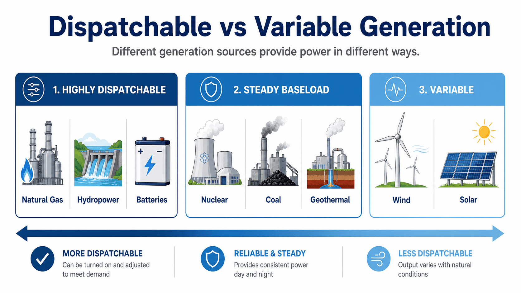
Generation value depends on when output is available and how quickly it can respond—not only on annual MWh or nameplate MW.
Dispatchable
Can be scheduled or controlled within operating constraints. Examples may include gas generation, hydro with storage, engines, and batteries.
Variable
Output is strongly driven by weather or resource availability. Wind and solar are the main examples, although controls can curtail output below what is available.
Flexible
Can start, stop, ramp, or change output quickly enough to support net-load changes, contingencies, or balancing requirements.
What Baseload Actually Means
Baseload is fundamentally a load concept: it is the relatively continuous minimum portion of demand. Historically, large plants with low variable cost and limited cycling capability were often described as baseload plants because they ran for long periods. Modern system planning increasingly focuses on flexibility, reserves, net load, ramping, and reliability contribution rather than treating “baseload” as a universal measure of resource quality.
Dependable Capacity vs. Nameplate Capacity
A resource’s dependable contribution can be less than nameplate rating because of ambient temperature, fuel constraints, hydrology, maintenance, forced outages, weather, energy duration, inverter limits, transmission constraints, or the coincidence between available output and peak system need.
EIA notes that grid operators must continuously balance generation with electricity demand and that generating units do not operate at full capacity every hour: EIA — Electricity Generation, Capacity, and Sales.
Current U.S. Electricity Generation Mix
In 2025, preliminary EIA data show natural gas remained the largest source of U.S. utility-scale electricity generation at about 41%, followed by renewable energy at about 24%, nuclear at about 18%, coal at about 17%, and petroleum/other sources at less than 1%.
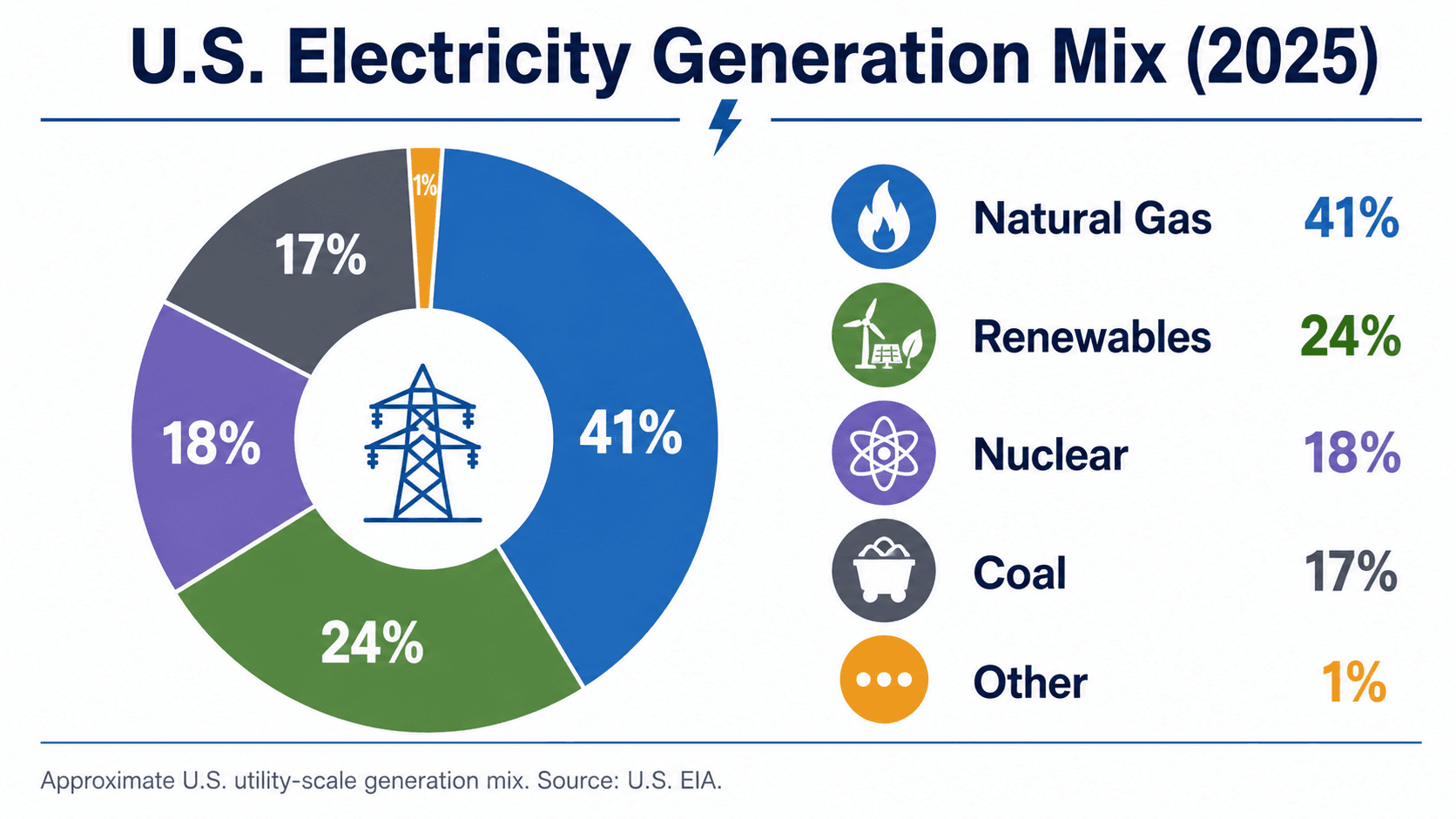
EIA reports approximately 4.43 trillion kWh of U.S. utility-scale electricity generation in 2025 and estimates additional generation from small-scale solar PV. National annual shares should not be used as a substitute for regional capacity, hourly dispatch, resource adequacy, transmission, or interconnection studies.
Source: U.S. Energy Information Administration — Electricity Generation, Capacity, and Sales in the United States. EIA identifies the 2025 figures as preliminary.
How Engineers Compare and Select Power Generation Resources
No generation technology is universally best. The correct choice depends on the electrical need, duty cycle, site, fuel or natural resource, grid connection, reliability requirement, environmental constraints, project economics, and operating strategy.
-
Define the electrical need.
Identify peak MW, annual MWh, load shape, critical loads, required duration, ramping needs, voltage level, resilience goals, and whether the resource must serve islanded or grid-connected operation.
-
Screen the available energy resources.
Evaluate fuel supply, pipeline capacity, solar irradiance, wind resource, water availability, geothermal resource, land, environmental limits, and storage charging opportunities.
-
Check the grid connection.
Review interconnection voltage, transformer and collector ratings, short-circuit duty, voltage control, reactive capability, protection coordination, dynamic performance, transmission capacity, and required system upgrades.
-
Compare operating behavior.
Consider start time, minimum load, ramp rate, availability, forced outages, maintenance, fuel security, weather exposure, inverter behavior, curtailment, and energy duration.
-
Evaluate lifecycle constraints.
Compare capital cost, operating cost, fuel, maintenance, emissions, water, land, permitting, tax/incentive assumptions, equipment life, replacement cycles, and decommissioning.
-
Verify the resource in system studies.
Use load flow, short-circuit, protection, stability, harmonic/power-quality, grounding, and interconnection studies appropriate to the project before treating the resource as electrically acceptable.
| Check | What to evaluate | Why it matters |
|---|---|---|
| Capacity and energy | Nameplate MW, net MW, expected MWh, capacity factor, availability | Separates maximum output from actual or dependable production |
| Timing and flexibility | Peak coincidence, ramp rate, start time, minimum load, duration | Determines whether the resource can meet the system need when it occurs |
| Electrical performance | Voltage, reactive power, fault current, ride-through, frequency response | Determines compatibility with protection, stability, and interconnection requirements |
| Site and resource | Fuel, solar, wind, water, land, geology, cooling, access | Controls achievable output, reliability, constructability, and operating cost |
| Grid deliverability | POI, transformer capacity, transmission constraints, system upgrades | A plant cannot deliver its full value if the network cannot accept or transport the output |
| Lifecycle | CAPEX, OPEX, fuel, maintenance, permits, emissions, replacement and decommissioning | Prevents one attractive metric from hiding a poor whole-project outcome |
Swipe horizontally to view all table columns.
Gross generator output is not the same as net power delivered to the grid. Pumps, fans, cooling equipment, fuel handling, heaters, controls, inverters, transformers, and other plant auxiliaries consume power or create losses. Engineers should distinguish generator-terminal MW, gross plant MW, auxiliary load, and net MW at the point of interconnection.
Power Generation Engineering References
These sources support the page’s explanations of electricity generation, current U.S. generation data, generator operation, capacity and grid balancing, and inverter-based-resource reliability considerations. Final project design requires current utility, owner, manufacturer, regulatory, and jurisdiction-specific requirements.
- U.S. Energy Information Administration — Electricity Explained Primary and secondary energy context and U.S. electricity-generation overview.
- U.S. Energy Information Administration — How Electricity Is Generated Generator, turbine, electromagnetic induction, and generation-method fundamentals.
- U.S. Energy Information Administration — Electricity Generation, Capacity, and Sales 2025 U.S. utility-scale generation, capacity, and grid-balancing context.
- North American Electric Reliability Corporation — 2025 State of Reliability Overview Bulk-power-system reliability and inverter-based-resource performance context.
- NERC — Findings From Inverter-Based Resource Model Quality Deficiencies Alert Dynamic-model quality, ride-through, and system-study considerations for inverter-based resources.
Frequently Asked Questions
What is power generation?
Power generation is the process of converting primary energy such as fuel, nuclear heat, water, wind, sunlight, geothermal heat, or stored energy into electrical power. Most conventional plants use a prime mover and generator, while solar PV and batteries use power-electronic converters and inverters.
What are the main types of power generation?
Major generation types include natural gas, coal, nuclear, hydropower, wind, solar PV, geothermal, biomass, reciprocating-engine generation, and energy storage. They differ in conversion method, fuel or resource, dispatchability, capacity factor, emissions, electrical behavior, and grid role.
How does a power plant generate electricity?
Many power plants use steam, combustion gas, water, or wind to turn a turbine connected to a generator. The generator converts mechanical rotation into electrical power through electromagnetic induction. Solar PV instead converts sunlight directly to DC electricity and uses an inverter to produce controlled AC output.
What is the difference between power generation and power distribution?
Power generation produces electrical energy. Transmission moves bulk power at high voltage between generating areas, substations, and load centers. Distribution delivers power locally from substations through feeders, transformers, and services to customers.
Is a battery a power generation source?
A battery energy storage system does not create primary energy; it stores electrical energy produced elsewhere and later returns it through a bidirectional converter. Operationally, however, a battery can inject real and reactive power and provide many services associated with generation resources.
What is capacity factor in power generation?
Capacity factor is actual electrical energy generated during a period divided by the energy the plant would have generated if it operated at rated output for the entire period. It measures utilization, not necessarily reliability contribution or peak-hour availability.
Summary and Next Step
Power generation begins with an energy resource but becomes a power-system engineering problem at the electrical terminals. The generating technology must produce usable power, operate within equipment limits, support the required voltage and frequency behavior, coordinate with protection, and connect to a network capable of accepting its output.
For engineering decisions, compare resources using both energy and system value: MW, MWh, capacity factor, availability, dispatchability, ramp rate, reactive capability, dynamic behavior, fuel or natural-resource risk, interconnection requirements, and lifecycle constraints.