Key Takeaways
- Core idea: Circuit analysis determines unknown voltages, currents, and power values by applying component laws and network constraints.
- Engineering use: It supports electronic design, troubleshooting, simulation review, signal conditioning, power supplies, filters, and system-level electrical decisions.
- What controls it: The result depends on topology, source type, component values, frequency, impedance, load connection, and reference directions.
- Practical check: Strong analysis includes sign convention review, unit checks, power balance, rating checks, and a model-versus-reality sanity check.
Table of Contents
Introduction
Circuit analysis is the engineering process of solving an electrical network for unknown voltage, current, and power. It combines device behavior, such as \(V = IR\), with network rules such as Kirchhoff’s laws so designers can predict how a circuit will operate, compare design choices, and troubleshoot measured behavior.
Circuit Analysis Equations at a Glance
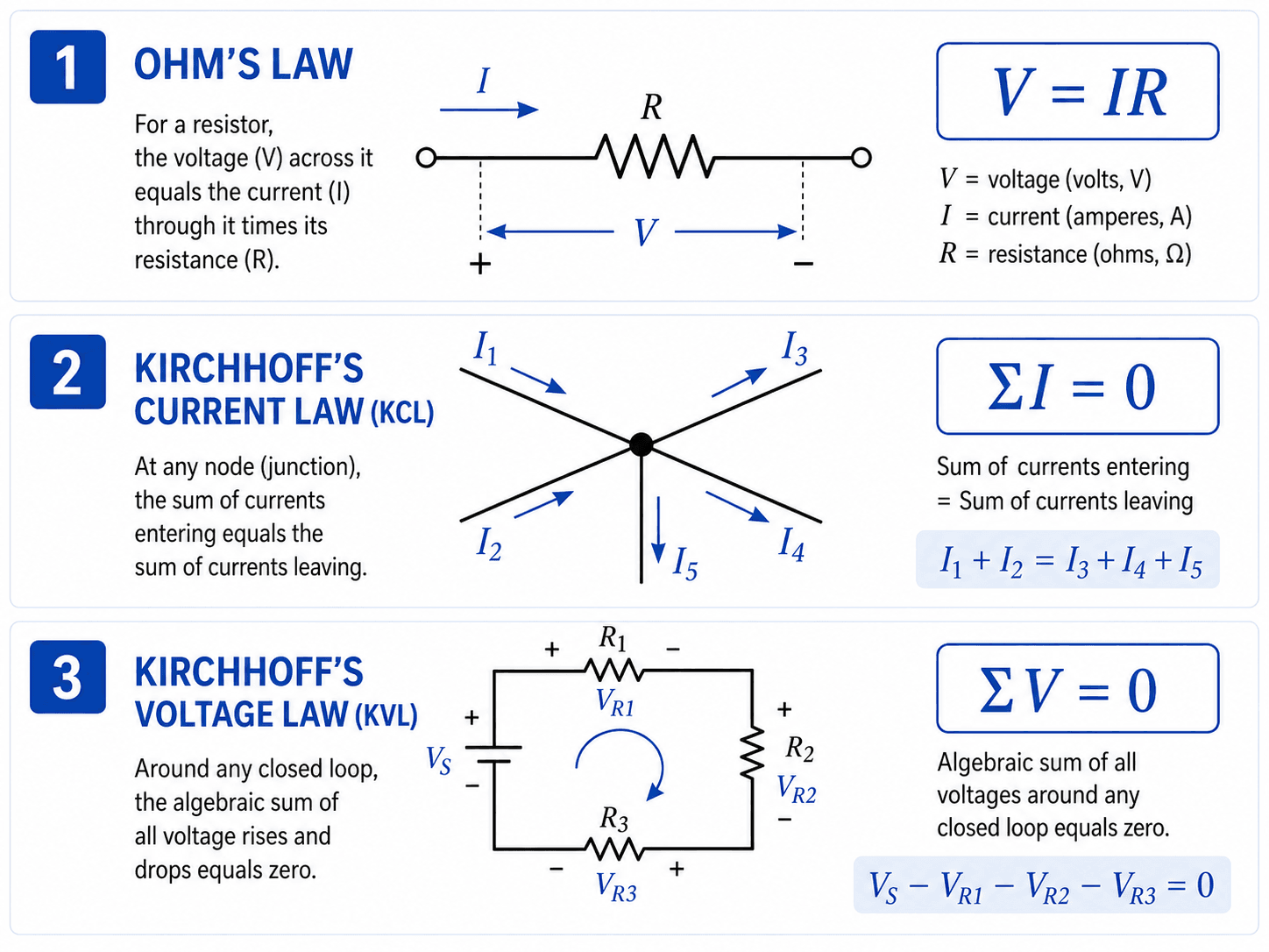
Read the graphic from top to bottom: first understand the voltage-current relationship through a component, then apply current balance at a node and voltage balance around a loop.
What Is Circuit Analysis?
Circuit analysis is the structured method engineers use to turn a schematic into numerical predictions. The unknowns may be a resistor current, a node voltage, a capacitor voltage over time, the gain of an amplifier stage, the current drawn by a load, or the power dissipated in a device.
In electronics engineering, the goal is rarely just to solve a math problem. The goal is to understand whether the circuit will bias correctly, stay inside component ratings, deliver the intended signal, avoid excessive heating, and behave predictably when tolerances, load changes, or frequency effects appear.
Start with Ohm’s Law, then learn KCL and KVL, then practice nodal analysis, mesh analysis, Thevenin and Norton equivalents, superposition, and AC phasor analysis.
The Three Foundations: Ohm’s Law, KCL, and KVL
Most circuit analysis can be traced back to three ideas: components create voltage-current relationships, currents must balance at a node, and voltages must balance around a closed loop. KCL reflects conservation of charge at a node, while KVL reflects conservation of energy around a closed path.
Ohm’s Law connects voltage, current, and resistance
For an ideal resistor, voltage is proportional to current:
\(V\) is voltage in volts, \(I\) is current in amperes, and \(R\) is resistance in ohms. Ohm’s Law is simple by itself, but it becomes powerful when it is combined with the rest of the circuit network.
Kirchhoff’s Current Law balances current at a node
Kirchhoff’s Current Law, or KCL, states that current entering a node must equal current leaving the node. In algebraic form, the sum of currents at a node is zero:
The sign convention is arbitrary, but it must be consistent. Currents entering the node can be treated as positive and leaving negative, or the reverse, as long as the same convention is used throughout the equation.
Kirchhoff’s Voltage Law balances voltage around a loop
Kirchhoff’s Voltage Law, or KVL, states that the algebraic sum of voltage rises and drops around a closed loop is zero:
KVL is the basis for mesh analysis and loop-based reasoning. It works well when loop currents are easier to define than node voltages, especially in planar circuits with fewer loops than nodes.
Types of Circuit Analysis
“Circuit analysis” is a broad phrase. The correct analysis type depends on whether the circuit is operating at a steady DC value, responding to a changing signal, switching between states, or being studied over a range of frequencies.
| Type of analysis | What it solves | Common electronics use |
|---|---|---|
| DC operating-point analysis | Steady voltages and currents after transients settle. | Biasing transistors, setting reference voltages, checking resistor currents, and confirming supply rails. |
| AC steady-state analysis | Sinusoidal voltage and current behavior using impedance, magnitude, and phase. | Filters, amplifiers, coupling networks, impedance matching, and frequency response review. |
| Transient analysis | How voltages and currents change with time after switching, charging, or disturbance. | RC timing, capacitor charging, inrush current, switching circuits, and startup behavior. |
| Small-signal analysis | Behavior around an operating point when signals are small enough for linearized models. | Amplifier gain, input impedance, output impedance, and analog signal behavior. |
| Power and thermal analysis | Power dissipation and stress in components, traces, connectors, and regulators. | Resistor wattage, regulator heating, MOSFET loss, supply loading, and component derating. |
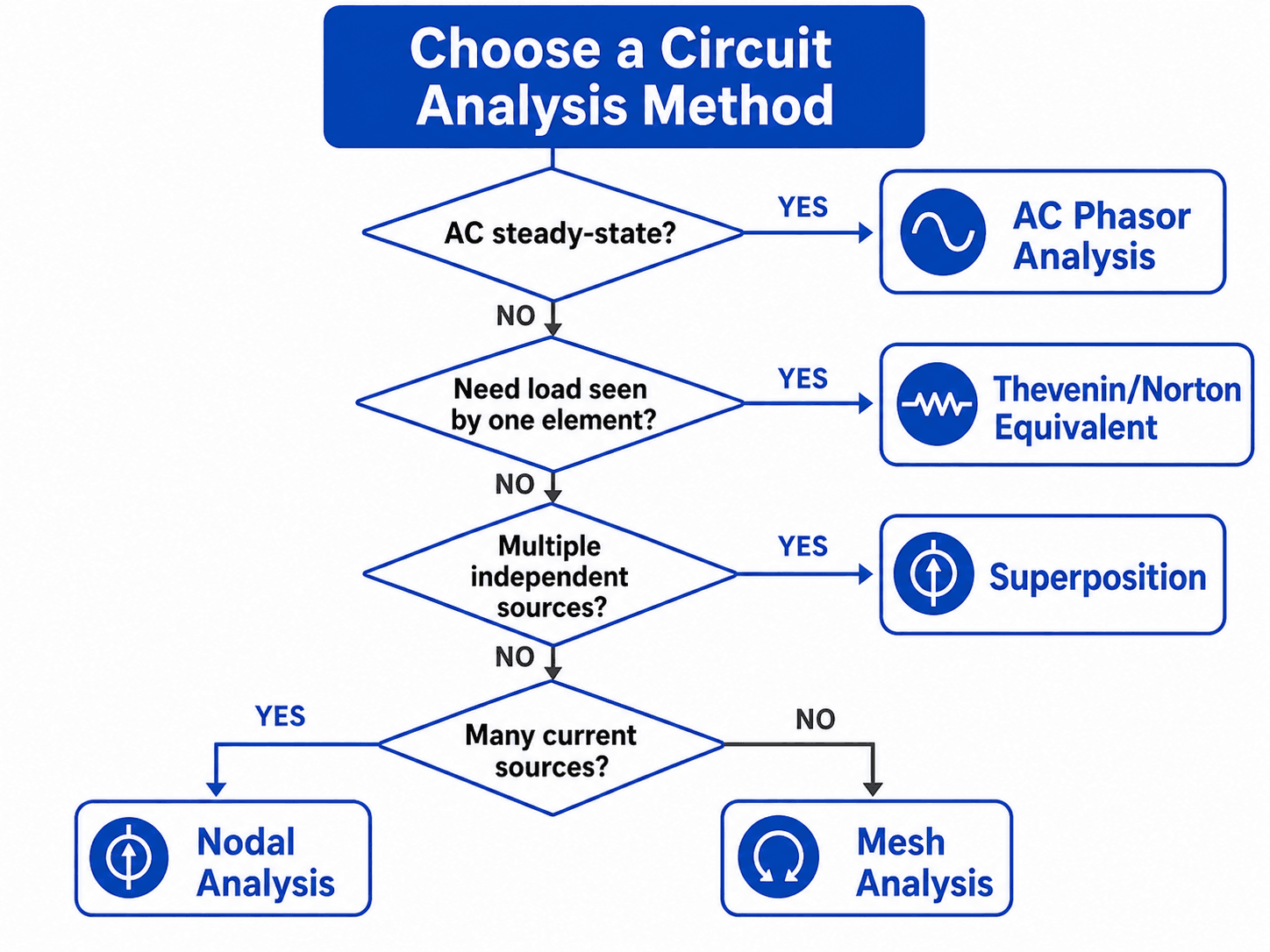
Main Circuit Analysis Methods
The best circuit-analysis method depends on the circuit topology and the question being asked. The same circuit may be solvable by several methods, but one method usually produces cleaner equations and fewer opportunities for sign mistakes.
| Method | Primary law or idea | Best for | Avoid or use care when | Typical unknown |
|---|---|---|---|---|
| Series and parallel reduction | Equivalent resistance or impedance | Circuits that can be simplified one group at a time. | Bridged or multi-node circuits do not reduce cleanly. | Equivalent \(R\), \(Z\), current, or voltage. |
| Voltage and current dividers | Ohm’s Law and series/parallel relationships | Quickly estimating output voltage or branch current in simple networks. | Loads change divider behavior if they are not included. | \(V_{out}\), branch current, or load current. |
| Nodal analysis | KCL | Circuits with many current sources, shared nodes, or non-planar layouts. | A poor reference node can make equations unnecessarily complex. | Node voltages. |
| Mesh analysis | KVL | Planar circuits with clear loops and convenient voltage sources. | Non-planar circuits or many current sources may be better solved with nodal analysis. | Mesh currents. |
| Superposition | Linearity | Linear circuits with multiple independent sources. | Do not superimpose power directly; dependent sources remain active. | Voltage or current contribution from each source. |
| Thevenin equivalent | Two-terminal equivalent source and resistance | Finding what a load sees from a network. | The equivalent only applies at the selected output terminals. | \(V_{th}\) and \(R_{th}\). |
| Norton equivalent | Two-terminal equivalent current source and resistance | Load-current calculations and source transformation work. | Terminal definition must be clear before simplifying the network. | \(I_N\) and \(R_N\). |
| AC phasor analysis | Complex impedance | Sinusoidal steady-state circuits with capacitors and inductors. | Transient switching behavior cannot be solved by phasors alone. | Complex voltage, current, impedance, magnitude, or phase. |
How Nodal Analysis Works
Nodal analysis solves a circuit by finding node voltages relative to a reference node. It is built around KCL: every non-reference node must have balanced current entering and leaving.
Basic nodal analysis steps
- Choose a reference node, usually the common return or ground node.
- Label the unknown node voltages, such as \(V_1\), \(V_2\), and \(V_3\).
- Write KCL at each unknown node.
- Express branch currents using Ohm’s Law or impedance relationships.
- Solve the simultaneous equations for node voltages.
- Use the solved voltages to calculate branch currents and power.
Simple nodal equation form
If a node \(V_1\) connects to a known source \(V_s\) through \(R_1\) and to ground through \(R_2\), KCL can be written as:
This equation says the algebraic sum of currents leaving the node is zero. If the solved voltage is negative, it means the node is below the chosen reference under the assumed sign convention.
Nodal analysis is often the fastest method when current sources are present because current sources fit directly into KCL equations.
How Mesh Analysis Works
Mesh analysis solves a circuit by assigning currents around the smallest closed loops, called meshes. It is built around KVL: the voltage rises and drops around each mesh must balance to zero.
Basic mesh analysis steps
- Confirm the circuit is planar, meaning it can be drawn without crossing branches.
- Assign a mesh current to each independent loop, usually clockwise for consistency.
- Write KVL around each mesh.
- For shared resistors, express the voltage drop using the difference between mesh currents.
- Solve the equations for mesh currents.
- Use the solved mesh currents to find component voltages and power.
Shared-resistor behavior
If two mesh currents pass through the same resistor in opposite directions, the resistor voltage depends on the current difference:
This shared-element term is where many mesh mistakes happen. The equation must match the direction of the mesh being written.
Mesh analysis is often efficient when a planar circuit has fewer loops than nodes and when voltage sources are easy to include in KVL equations.
DC vs. AC Circuit Analysis
DC circuit analysis often treats voltages and currents as constant values. AC circuit analysis must account for sinusoidal waveforms, impedance, frequency, RMS or peak conventions, and phase relationships. That difference changes how capacitors, inductors, filters, transformers, and signal paths are interpreted.
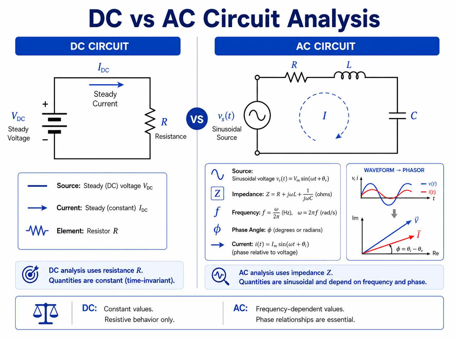
DC analysis
In a DC resistor network, the main unknowns are usually steady voltages, steady currents, and power dissipation. The simplest assumption is that component values do not change with time, temperature, or operating point.
AC analysis
In AC steady-state analysis, resistance is extended to impedance. For a series RLC branch, the total impedance is:
For parallel or mixed AC circuits, impedances are combined using the appropriate series and parallel network rules while preserving complex values. RMS, peak, and peak-to-peak values should not be mixed without conversion.
Variables and Conditions That Control Circuit Analysis
Circuit analysis is controlled by more than the values printed on a schematic. The source type, reference directions, topology, component model, frequency, and loading condition all influence the result and how the result should be interpreted.
| Control | Why it matters | Engineering implication |
|---|---|---|
| Reference node | All node voltages are measured relative to a chosen ground or reference point. | A good reference node reduces algebra and makes the solved voltages easier to interpret. |
| Current direction | Current arrows define the sign convention before solving. | A negative result usually means the real direction is opposite the assumed direction. |
| Component model | Real components may include parasitic resistance, capacitance, inductance, leakage, or nonlinear behavior. | The correct model depends on whether the task is a quick estimate, detailed design, or troubleshooting review. |
| Frequency | Capacitors and inductors change impedance with frequency. | Filters, amplifiers, coupling networks, and sensor interfaces require frequency-aware analysis. |
| Load connection | Connecting a load changes the circuit operating point. | A voltage divider, sensor output, or amplifier stage can look correct unloaded and fail when the real load is connected. |
| Power and thermal limits | Current and voltage determine component power dissipation. | A circuit may solve mathematically but still overheat a resistor, regulator, transistor, trace, or connector. |
Core Equations Used in Circuit Analysis
A useful circuit-analysis equation should be tied to a clear physical question. Are you solving a resistor voltage, a node balance, a loop voltage, a power limit, or an AC impedance relationship? The equations below appear repeatedly in electronics and power circuits.
- \(V\) Voltage difference between two points, measured in volts.
- \(I\) Current through a branch or component, measured in amperes.
- \(R\) Resistance, measured in ohms, used for ideal resistive behavior.
- \(P\) Power, measured in watts, used to check dissipation and source/load behavior.
- \(Z\) Impedance, measured in ohms, used in AC analysis to include magnitude and phase behavior.
- \(j\) Imaginary unit used in phasor and impedance calculations.
- \(\omega\) Angular frequency in radians per second, where \(\omega = 2\pi f\).
- \(\phi\) Phase angle between sinusoidal voltage and current.
The most important practical habit is to keep the equation tied to a reference direction. Voltage polarity and current direction are not decoration; they define whether a component is absorbing or delivering power.
Circuit Analysis Workflow and Sanity Check
A reliable workflow prevents most beginner and intermediate mistakes. The goal is to define the circuit clearly before writing equations, then check whether the solution makes physical sense after the math is complete.
Identify the circuit type, label voltage polarities and current directions, choose a reference node, select the simplest method, write equations from KCL/KVL/component laws, solve the unknowns, then check signs, units, power balance, and component ratings.
| Analysis check | What to look for | Why it matters |
|---|---|---|
| Reference choice | Use a ground node connected to many elements or the most logical circuit return. | A poor reference node can turn a simple nodal problem into a messy system of equations. |
| Sign convention | Confirm voltage polarity and current arrows before solving. | Most negative answers are sign-convention messages, not automatic calculation failures. |
| Unit consistency | Use volts, amperes, ohms, watts, farads, henries, and hertz consistently. | Mixing milliamps with amps or kilohms with ohms can move answers by factors of 1,000. |
| Power balance | Compare power supplied with power absorbed in ideal steady-state circuits. | Large mismatches often reveal sign errors, missing branches, or wrong component relationships. |
| Rating check | Compare solved voltage, current, and power with component limits. | A mathematically valid circuit can still exceed resistor wattage, regulator current, diode reverse voltage, or trace capacity. |
| Model check | Ask whether ideal assumptions are accurate enough for the frequency, temperature, and load condition. | Parasitics and nonlinear behavior may dominate in high-speed, high-power, low-noise, or switching circuits. |
Worked Example: Loaded Voltage Divider
A voltage divider is one of the most common places where simple circuit analysis can mislead beginners. The unloaded divider equation may look correct, but a connected load changes the actual output voltage.
Step 1: Solve the unloaded divider
Suppose \(V_{in} = 12\,V\), \(R_1 = 10\,k\Omega\), and \(R_2 = 10\,k\Omega\). With no load connected, the output voltage is:
Step 2: Add the load resistance
Now connect a \(10\,k\Omega\) load from \(V_{out}\) to ground. That load is in parallel with \(R_2\), so the lower resistance becomes:
Step 3: Recalculate the actual output voltage
The loaded output voltage is:
The engineering lesson is that the load changed the circuit. The unloaded divider predicted \(6\,V\), but the real connected circuit produces \(4\,V\). This is why circuit analysis must include what the source or signal actually drives.
Circuit Analysis vs. Circuit Simulation
Circuit simulation is useful because software can solve large networks faster than hand calculations. Circuit analysis is still necessary because simulation results only make sense when the engineer understands the assumptions, models, sources, loads, and expected behavior.
| Question | Circuit analysis helps with | Simulation helps with |
|---|---|---|
| Why does the circuit behave this way? | Explaining current paths, voltage drops, bias points, and limiting assumptions. | Showing numerical results across many nodes and conditions. |
| What happens if a component changes? | Identifying which variable controls the result. | Sweeping component values quickly. |
| Is the result physically reasonable? | Checking signs, units, power balance, and expected magnitudes. | Flagging unusual voltages, currents, or waveforms for review. |
| What can go wrong? | Finding missing loads, wrong reference points, bad sign conventions, and rating issues. | Testing startup, transients, frequency response, and tolerances when models are accurate. |
A good workflow is to analyze a simplified circuit first, simulate the detailed circuit next, and then compare both against measurements. If all three disagree, the most likely problem is a missing assumption, an incorrect model, or a measurement setup issue.
How Engineers Use Circuit Analysis in Real Design Work
Circuit analysis is used any time an engineer needs to predict electrical behavior before a circuit is built, revised, simulated, or tested. In electronics engineering, that includes everything from a simple LED current-limiting resistor to amplifier biasing, power supply filtering, sensor interfaces, and embedded-system input protection.
- Electronics design: checking bias points, signal levels, component stress, current paths, and frequency response.
- Power circuits: estimating voltage drop, load current, power loss, fault current, and supply behavior.
- Troubleshooting: comparing measured voltages and currents against expected circuit behavior to isolate opens, shorts, wrong component values, and loading problems.
- Model validation: confirming that simulation assumptions match actual schematic topology and measurement conditions.
When a measured circuit does not match the analysis, do not immediately assume the math is wrong. First check the reference point, meter loading, component tolerance, source limit, wiring error, and whether the circuit is operating outside the ideal model.
Engineering Judgment and Field Reality
Textbook circuit analysis often assumes ideal wires, ideal components, and exact source values. Real circuits are less clean. A resistor warms up, a capacitor has equivalent series resistance, an inductor saturates, a breadboard adds stray capacitance, and a power supply may enter current limit before the schematic reaches its expected operating point.
Experienced engineers use circuit analysis as the baseline, then ask what the model leaves out. That is especially important in high-current paths, high-frequency signals, switching circuits, sensor inputs, precision analog designs, and systems where small impedance or grounding assumptions can change the result.
The voltage you calculate is usually a voltage between two named points. The voltage you measure depends on where the meter leads are placed, whether the circuit is loaded, and whether the reference point in the real system matches the reference point used in the analysis.
When This Breaks Down
Basic circuit analysis becomes unreliable when the assumed model no longer represents the physical circuit. The equations may still be mathematically correct, but the model may be missing behavior that controls the real answer.
- Nonlinear devices: diodes, transistors, LEDs, MOSFETs, and regulators often require operating-point models rather than simple resistance.
- High-frequency layouts: traces, vias, connectors, and component leads can behave like transmission lines, inductors, or capacitors.
- Thermal effects: resistance, leakage, gain, and threshold voltage can shift as components heat up.
- Source limitations: real supplies have current limits, internal resistance, ripple, transient response, and protection behavior.
- Unmodeled loading: meters, ADC inputs, downstream circuits, and protection devices can change the node voltage being analyzed.
- EMI and layout effects: noise coupling, loop area, return-path inductance, and PCB layout can dominate behavior that is not visible in a simple schematic.
Common Circuit Analysis Mistakes and Practical Checks
Most circuit-analysis errors are not advanced math problems. They are reference, sign, topology, unit, or modeling mistakes. A disciplined review catches them before the result is used for a design decision.
| Common mistake | Why it causes trouble | Practical check |
|---|---|---|
| Changing current direction halfway through the problem | The equation signs stop matching the original reference directions. | Draw arrows once, then let negative answers indicate opposite direction. |
| Using ground as if it always means earth | In many electronics circuits, ground is a reference node, not necessarily a physical earth connection. | Identify the circuit return/reference before interpreting measured voltages. |
| Forgetting that loads affect divider voltages | A connected load can pull current and change the expected output voltage. | Include load resistance or input impedance in the equivalent circuit. |
| Applying DC intuition to capacitors and inductors in AC circuits | Frequency-dependent impedance and phase shift can dominate behavior. | Use impedance and phasors for sinusoidal steady-state analysis. |
| Mixing RMS, peak, and peak-to-peak values | AC voltage and current magnitudes can be represented in different ways. | Confirm whether values are RMS, peak, or peak-to-peak before using them in equations. |
| Turning off dependent sources during superposition | Dependent sources are controlled by circuit variables and must remain active. | Only deactivate independent sources when applying superposition. |
| Checking voltage and current but not power | Components may be electrically correct but thermally overstressed. | Calculate \(P = VI\), \(P = I^2R\), or \(P = V^2/R\) where appropriate. |
Do not treat a schematic as the same thing as the physical circuit. Long leads, shared return paths, connector resistance, breadboard parasitics, and measurement ground points can all change what the circuit actually does.
Useful References and Design Context
Circuit analysis is a foundational topic, so the most useful reference is often a clear educational source that explains the formal basis for nodal and mesh methods without turning the page into a code or product document.
- MIT OpenCourseWare: MIT OpenCourseWare notes on node and mesh circuit analysis provide a deeper academic explanation of how KCL, KVL, and Ohm’s Law support nodal and mesh solution methods.
- Project-specific criteria: In real design work, component datasheets, product requirements, safety margins, operating environment, and applicable electrical standards may control the final acceptable circuit design.
- Engineering use: Use formal references to strengthen the method, then use practical review checks to confirm that the chosen model fits the actual circuit and operating condition.
Frequently Asked Questions
Circuit analysis is the process of finding unknown voltages, currents, and power values in an electrical circuit. It uses component behavior, Kirchhoff’s laws, and structured methods so an engineer can predict how a circuit will behave before building, simulating, testing, or troubleshooting it.
The main methods include series and parallel reduction, Ohm’s Law, Kirchhoff’s Current Law, Kirchhoff’s Voltage Law, nodal analysis, mesh analysis, superposition, source transformation, and Thevenin or Norton equivalent circuits. AC circuit analysis also uses impedance and phasors.
Use nodal analysis when the circuit has clear node voltages, many current sources, or a non-planar layout. Use mesh analysis when the circuit is planar, has fewer loops than nodes, and voltage sources make loop equations straightforward.
DC circuit analysis often treats values as constant and uses resistance directly. AC circuit analysis must account for sinusoidal behavior, frequency, impedance, RMS or peak conventions, and phase angle because capacitors and inductors do not behave like simple resistors.
A negative current or voltage usually means the actual direction or polarity is opposite the reference direction chosen at the start of the problem. It does not automatically mean the calculation is wrong; it often confirms that the assumed direction was reversed.
Summary and Next Steps
Circuit analysis is the foundation for understanding how electrical and electronic circuits behave. It combines component equations, Kirchhoff’s laws, topology, source behavior, and practical assumptions to solve for voltages, currents, power, impedance, and operating limits.
The most useful approach is systematic: label the circuit, choose the simplest method, solve the equations, then check signs, units, power, component ratings, and whether the model reflects the real circuit.
Where to go next
Continue your learning path with related Turn2Engineering resources.
-
Basic Electronic Components
Review resistors, capacitors, inductors, diodes, transistors, and other devices that appear in circuit-analysis problems.
-
Circuit Simulation
Learn how simulation tools extend circuit analysis into larger designs, frequency sweeps, transients, and model-based testing.
-
Voltage Divider Calculator
Practice one of the most common circuit-analysis applications: predicting output voltage from resistor ratios and load effects.