
Key Takeaways
- Core idea: Feedback control measures the output, compares it with a reference or setpoint, and uses the resulting error to adjust the system input.
- Engineering use: Feedback control is used in motors, voltage regulators, thermostats, robotics, process control, cruise control, and many closed-loop control systems.
- What controls it: Loop gain, feedback sign, sensor behavior, plant dynamics, time delay, actuator limits, and controller tuning determine whether the loop behaves well.
- Practical check: A feedback loop should be checked for steady-state error, overshoot, settling time, disturbance rejection, stability margin, noise, and saturation.
Table of Contents
Introduction
Feedback control is a closed-loop control method where a system measures its output, compares it with a desired setpoint, and uses the error to adjust the input. In control systems engineering, feedback is what allows real systems to reject disturbances, reduce steady-state error, and keep performance close to the intended target.
Feedback Control System Diagram
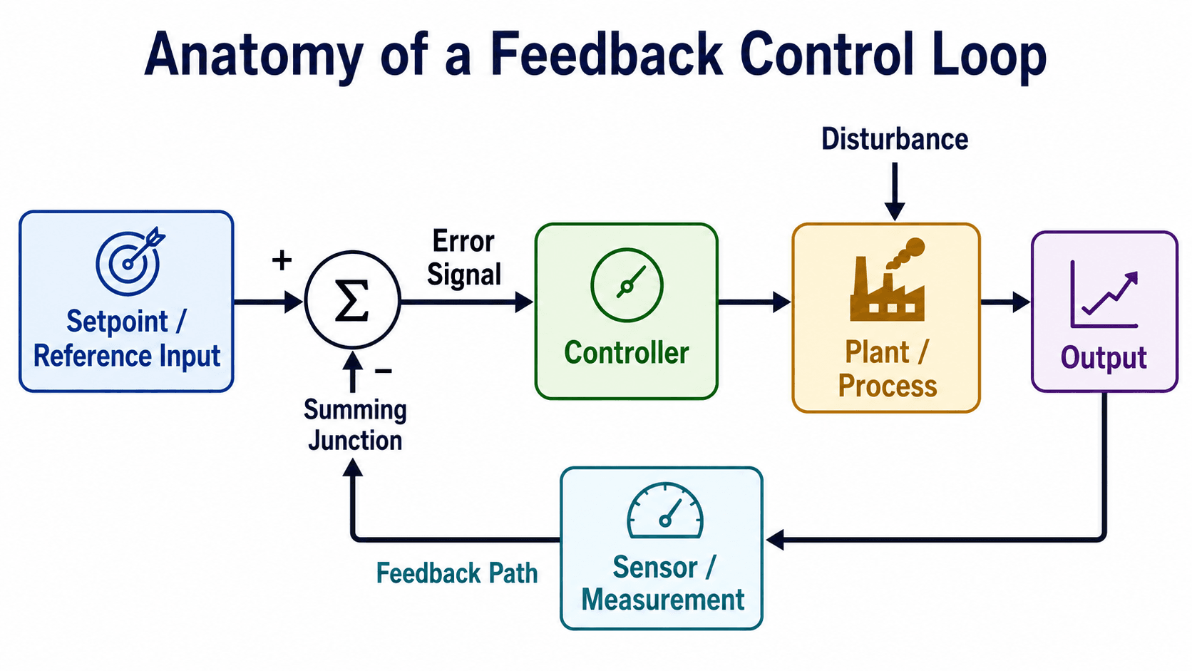
The defining feature is the return path. Without measured output feeding back to the summing junction, the controller cannot know whether the system actually reached the target.
What Is Feedback Control?
Feedback control is a control strategy that continuously compares a desired value with the measured output of a system. The controller acts on the difference, called the error signal, so the plant or process moves closer to the setpoint. Because the output is measured and reused, feedback control is a form of closed-loop control.
In electrical and control systems engineering, feedback is used whenever the real output may drift because of changing load, disturbances, model uncertainty, component tolerances, or operating conditions. A motor speed controller, for example, does not simply apply a fixed voltage and hope the motor spins at the right speed. It measures speed, compares it to the command, and adjusts the drive signal when the load changes.
Feedback control is not just “automatic control.” The defining feature is measurement of the output and correction based on the difference between actual behavior and desired behavior.
How a Feedback Control System Works
A basic feedback control system starts with a reference input or setpoint. The measured output is subtracted from that reference to form an error signal. The controller converts the error into a control signal, the plant responds, the sensor measures the output, and the measurement returns to the summing junction.
Main Parts of a Feedback Control Loop
| Loop element | What it does | Practical control-system meaning |
|---|---|---|
| Setpoint or reference | Defines the desired output value. | A commanded speed, voltage, temperature, position, pressure, level, or other target. |
| Summing junction | Computes the error between the reference and measured output. | The sign convention here determines whether the loop corrects error or accidentally reinforces it. |
| Error signal | Shows how far the measured output is from the desired value. | The controller usually acts on this signal rather than on the output directly. |
| Controller | Converts error into a control action. | This may be a proportional, PI, PID, digital, state-space, or custom control algorithm. |
| Plant or process | The physical or modeled system being controlled. | Examples include a motor, heater, aircraft axis, robotic joint, power converter, valve, or tank. |
| Sensor or measurement | Measures the output and sends it back to the loop. | Measurement noise, delay, calibration error, and resolution can limit real feedback performance. |
| Disturbance | Pushes the output away from the desired value. | Load torque, temperature change, supply variation, pressure fluctuation, or external force can create error. |
Continuous-Time and Digital Feedback
Feedback control can be implemented with analog circuits, continuous-time models, digital controllers, programmable logic, embedded software, or computer-based control systems. The same loop idea still applies, but digital feedback also introduces sampling rate, quantization, computation delay, and discrete-time stability considerations.
Negative Feedback Control vs Positive Feedback
Most engineering control loops use negative feedback because the measured output is subtracted from the reference. If the output rises above the setpoint, the error changes in a direction that reduces the output. If the output falls below the setpoint, the controller increases the command to bring it back.
| Feedback type | What it does | Engineering implication |
|---|---|---|
| Negative feedback control | Acts to reduce the error between the reference and measured output. | Used for regulation, tracking, disturbance rejection, and stable closed-loop behavior. |
| Positive feedback | Reinforces the change instead of opposing it. | Can be useful in oscillators and switching circuits, but unintended positive feedback can create runaway or instability. |
| Wrong feedback sign | Makes a control loop respond in the opposite of the intended direction. | A common commissioning failure that can make a stable-looking block diagram behave dangerously in hardware. |
Always verify the feedback sign before increasing gain. A loop with the wrong sign may look correct on paper but drive the output farther away from the setpoint.
Feedback Control vs Open-Loop and Feedforward Control
The difference between feedback, open-loop, and feedforward control is how the controller uses information. Open-loop control applies a command without checking the result. Feedback control corrects based on measured output. Feedforward control acts on a known or measured disturbance before the output fully changes.
| Control approach | How it behaves | Best fit | Main limitation |
|---|---|---|---|
| Open-loop control | Applies a command without measuring the final output. | Simple systems where disturbances are small and the input-output relationship is predictable. | Cannot automatically correct for load changes, drift, wear, or unexpected disturbances. |
| Feedback control | Measures output and corrects the command based on error. | Systems that need accuracy, disturbance rejection, tracking, or regulation under changing conditions. | Requires sensors, tuning, stability review, and attention to noise and delay. |
| Feedforward control | Measures or estimates a disturbance before it fully affects the output. | Systems where the disturbance is measurable and predictable before the output changes. | Usually depends on an accurate process model and often still needs feedback for correction. |
Feedback Control vs Feedforward Control
Feedback control is reactive because it corrects after the output measurement shows error. Feedforward control is predictive because it adjusts the input based on a known disturbance or command change before the output fully responds. Many high-performance systems use both: feedforward handles predictable effects, while feedback removes the remaining error.
Feedback Control Transfer Function
A feedback control transfer function shows how the reference input becomes the output after the loop is closed. For a standard negative feedback system with forward-path transfer function \(G(s)\) and feedback-path transfer function \(H(s)\), a common closed-loop form is:
This equation is useful because the denominator contains the loop behavior. The term \(1+G(s)H(s)\) influences sensitivity, bandwidth, disturbance rejection, and stability. If that denominator produces unstable closed-loop poles, the system can oscillate or diverge even if the individual controller and plant blocks look reasonable by themselves.
- \(R(s)\) Reference input or setpoint expressed in the Laplace domain.
- \(Y(s)\) System output expressed in the Laplace domain.
- \(G(s)\) Forward-path transfer function, often including the controller and plant depending on the block diagram convention.
- \(H(s)\) Feedback-path transfer function, often representing the sensor, measurement filter, or feedback scaling.
- \(G(s)H(s)\) Loop transfer function, which strongly affects stability margin and frequency-response behavior.
The equation is a compact model, not a complete design check. Engineers still review pole locations, time response, frequency response, sensor behavior, actuator limits, and robustness before trusting a feedback design.
How Feedback Control Rejects Disturbances
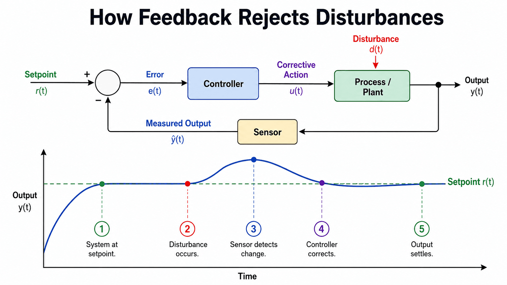
Disturbance rejection is one of the main reasons engineers use feedback control. When a load, environmental change, or process disturbance moves the output away from the setpoint, the sensor detects the output change, the error signal changes, and the controller drives the plant back toward the target.
Example: Motor Speed Under Changing Load
Consider a motor drive commanded to hold a fixed shaft speed. If the mechanical load suddenly increases, the motor slows down. A speed sensor detects the lower output speed, the error signal increases, and the controller commands more torque or current until the speed recovers.
Why Feedback Correction Is Not Instant
Feedback reacts after the measured output changes, so the response always depends on sensor delay, controller computation, actuator speed, and plant dynamics. This is why real feedback systems may show overshoot, undershoot, or settling time even when the final error is small.
Stable, Oscillatory, and Unstable Feedback Response
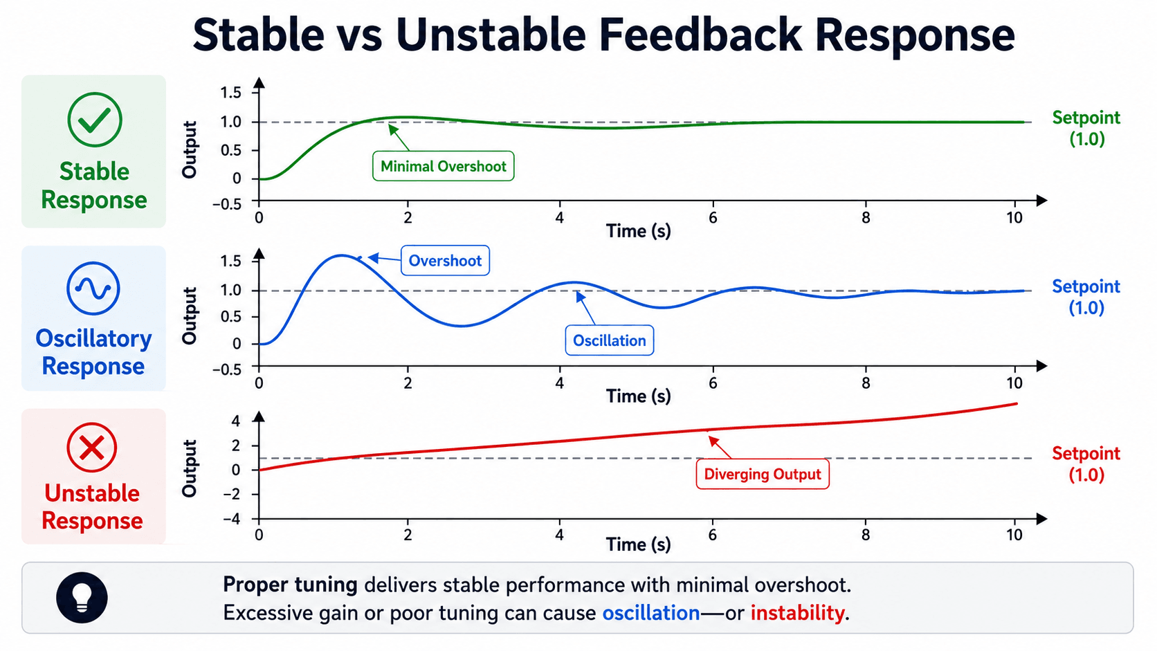
Feedback can improve accuracy, but it also changes the dynamics of the system. A well-tuned loop moves the output toward the setpoint without excessive overshoot. A poorly tuned loop may oscillate. A loop with too much gain, too much phase lag, too much delay, or the wrong feedback sign can become unstable.
The Gain Tradeoff
Increasing loop gain often reduces steady-state error and improves disturbance rejection at low frequencies. However, higher gain can also increase overshoot, amplify noise, excite unmodeled dynamics, or reduce stability margin. The engineering goal is not maximum gain; it is enough gain to meet performance requirements while keeping the loop robust.
Delay and Phase Lag Matter
Time delay is especially dangerous in feedback systems because the controller may react to old information. If the measured output arrives late enough, the controller can add energy in the wrong phase of the response, turning correction into oscillation.
Feedback Control Performance Metrics
Engineers rarely judge a feedback control system by a single result. A loop may reach the setpoint eventually but still overshoot too far, settle too slowly, amplify noise, or become fragile when operating conditions change. The metrics below help connect the diagram to real performance.
| Performance metric | What it means | What feedback control changes |
|---|---|---|
| Steady-state error | The final difference between the setpoint and output after transients settle. | Feedback often reduces this error, especially when integral action or high low-frequency loop gain is used. |
| Rise time | How quickly the output first approaches the target. | Higher loop gain can make the response faster, but may reduce damping. |
| Overshoot | How far the output exceeds the setpoint during the transient response. | Aggressive tuning can increase overshoot even when final error is small. |
| Settling time | How long the output takes to remain near the target band. | Depends on damping, plant dynamics, controller tuning, and actuator behavior. |
| Disturbance rejection | How well the loop recovers after an external change pushes the output away from target. | Feedback improves recovery when the disturbance affects a measured output and the actuator has enough authority. |
| Stability margin | How much gain or phase change the loop can tolerate before oscillation or instability. | Feedback must be tuned so performance improves without making the loop fragile. |
| Noise sensitivity | How much measurement noise appears in the control action or output. | High gain and derivative action can make the controller react strongly to noisy measurements. |
Feedback Control Examples
Feedback control appears anywhere engineers need a system to hold, track, regulate, or stabilize a variable despite disturbances. It is used across electrical, mechanical, aerospace, process, robotics, automotive, biomedical, and power systems applications.
| Application | Controlled output | Typical disturbance | Why feedback helps |
|---|---|---|---|
| DC motor speed control | Motor speed | Changing mechanical load | Adjusts drive voltage or current when the shaft slows down or speeds up. |
| Voltage regulation | Output voltage | Load current changes or supply variation | Maintains voltage close to the desired value despite changing demand. |
| Thermostat or temperature control | Room, plate, oven, or process temperature | Ambient temperature, heat loss, or process load | Turns heating or cooling action up or down based on measured temperature error. |
| Robotic joint control | Position, velocity, or torque | Payload change, friction, or external force | Corrects motion so the joint follows the commanded trajectory. |
| Cruise control | Vehicle speed | Road grade, wind, or changing drag | Adjusts throttle or power command to keep speed near the driver’s setpoint. |
| Tank level control | Fluid level | Inflow or outflow change | Adjusts valve or pump action to maintain the desired level. |
Feedback control is usually most valuable when disturbances are uncertain, the plant model is imperfect, or the output must stay near a target even as operating conditions change.
Senior Engineer Feedback Loop Review Checklist
A feedback loop should be reviewed as a complete measurement-control-action system, not just a controller equation. The checklist below focuses on practical details that often separate a stable lab model from a reliable real-world control loop.
Start with the controlled variable, confirm the feedback sign, check the sensor and actuator, review the dynamic response, then evaluate stability margin and failure modes. If any of those pieces are weak, controller tuning alone may not fix the problem.
| Feedback loop check | What to look for | Why it matters |
|---|---|---|
| Controlled variable | The sensor measures the output the design actually needs to regulate. | Controlling a convenient proxy variable can leave the true performance variable drifting. |
| Feedback sign | An increase in output should reduce the correcting command when the output is already too high. | The wrong sign turns negative feedback into positive feedback and can make the system run away. |
| Sensor quality | Noise, calibration error, delay, bandwidth, and resolution are acceptable for the control objective. | The loop can only correct based on what it measures; poor measurement creates poor control action. |
| Actuator authority | The actuator can deliver enough range, speed, and force/current/flow to correct expected errors. | A controller command is useless if the actuator saturates or responds too slowly. |
| Response quality | Rise time, overshoot, settling time, steady-state error, and disturbance recovery meet the design need. | A loop can be stable but still too slow, too oscillatory, or too inaccurate for the application. |
| Stability margin | Gain and phase margin remain reasonable across expected operating conditions. | Real plants change with load, temperature, wear, and model error, so marginal stability is risky. |
| Failure behavior | Sensor loss, actuator saturation, communication delay, and controller faults have predictable responses. | Feedback loops can fail in ways that are not obvious from the ideal block diagram. |
Engineering Judgment and Field Reality
Textbook feedback diagrams often assume a clean measurement, a linear plant, unlimited actuator authority, and a controller that updates instantly. Real systems rarely behave that cleanly. Sensors are filtered, actuators saturate, signals are sampled, mechanical systems have backlash and friction, and plants may change with operating point.
Experienced engineers look for the non-ideal pieces of the loop before tuning the controller. A noisy sensor may require filtering, but filtering adds delay. A larger controller gain may reduce tracking error, but it can also excite flexible modes, switching ripple, or high-frequency measurement noise. A stable simulation may still fail if the model left out the slowest thermal lag or the fastest actuator limit.
If a feedback loop only works in simulation with perfect measurement and no limits, it is not finished. The loop should be checked against noise, delay, saturation, model uncertainty, and realistic disturbances.
When This Breaks Down
The simple feedback control model becomes less reliable when the real system violates the assumptions behind the loop diagram or transfer function. This does not make feedback useless, but it changes the design problem from simple error correction to robustness, modeling, filtering, and safety review.
- Wrong feedback sign: The measured output reinforces the error instead of reducing it, creating positive feedback behavior.
- Large time delay: The controller reacts to old output information and may correct in the wrong direction for the current state.
- Actuator saturation: The controller requests more action than the actuator can deliver, increasing overshoot or recovery time.
- Sensor noise: The controller reacts to measurement noise instead of true output behavior, especially when derivative action or high gain is used.
- Unmodeled dynamics: Flexible modes, resonance, backlash, transport lag, switching behavior, or nonlinear friction can appear outside the simplified model.
- Operating point changes: A loop tuned for one speed, load, temperature, or pressure may perform poorly at another condition.
Common Feedback Control Mistakes
Feedback control is powerful, but many control problems come from applying the concept too casually. The common mistakes below are especially important because they can make a loop look correct on a block diagram while behaving poorly in hardware or simulation.
- Assuming more gain is always better: Higher gain may reduce error, but it can also reduce phase margin and create oscillation.
- Ignoring the sensor: A slow, noisy, or poorly calibrated sensor can dominate the loop behavior.
- Treating feedback as disturbance prevention: Feedback usually corrects after the output moves; it does not always prevent the first deviation.
- Using open-loop intuition for closed-loop behavior: Closing the loop changes poles, bandwidth, sensitivity, and transient response.
- Checking final value but not transient response: A system can eventually reach the setpoint while still overshooting too far or settling too slowly.
- Forgetting actuator limits: Saturation can cause sluggish recovery, overshoot, integral windup, or loss of control authority.
- Assuming feedback always means PID: PID control is common, but feedback can also use lead-lag, state-space, model-based, adaptive, digital, or custom controller structures.
Do not approve a feedback loop just because the steady-state error is small. Always check stability, overshoot, settling time, disturbance recovery, sensor behavior, and actuator limits.
Feedback Control References and Design Context
Feedback control can be introduced with a simple loop diagram, but engineering design usually requires dynamic analysis. Transfer functions, loop gain, sensitivity, and stability margins help engineers understand why a feedback loop improves one part of performance while potentially creating oscillation somewhere else.
- Stanford University EE102: Dynamic analysis of feedback systems explains closed-loop transfer functions, loop transfer functions, sensitivity, and stability behavior in feedback systems.
- Project-specific criteria: Control requirements should still be checked against the actual plant, sensor, actuator, sampling rate, operating range, and performance target.
- Engineering use: In practice, feedback control is reviewed with time-response plots, frequency-response tools, root locus methods, model validation, and hardware limitations.
Frequently Asked Questions
Feedback control is a way to control a system by measuring its output, comparing that output with the desired target, and using the difference to adjust the input. The goal is to reduce error so the system output stays closer to the setpoint.
Negative feedback control subtracts the measured output from the reference input so the controller acts to reduce error. If the output is too high, the correction pushes it down; if the output is too low, the correction pushes it up.
Open-loop control applies an input without checking the output, while feedback control measures the output and corrects the input based on the error. Feedback control usually handles disturbances and uncertainty better, but it requires measurement, tuning, and stability checks.
Yes. Feedback can improve accuracy and disturbance rejection, but excessive loop gain, time delay, phase lag, actuator saturation, sensor noise, or the wrong feedback sign can make the response oscillate or become unstable.
Yes. PID control is one of the most common feedback control methods. It uses proportional, integral, and derivative action on the error signal to adjust the control input and improve tracking, steady-state accuracy, and response behavior.
Summary and Next Steps
Feedback control is the foundation of closed-loop control systems. It measures output, compares that measurement with a target, and uses the resulting error to adjust the system input. This makes it possible to improve tracking, reject disturbances, and reduce sensitivity to changing operating conditions.
The practical challenge is that feedback changes system dynamics. A good loop must be reviewed for sensor quality, actuator authority, feedback sign, gain, phase lag, overshoot, settling time, stability margin, and realistic disturbances—not just whether it eventually reaches the setpoint.
Where to go next
Continue your learning path with related Turn2Engineering resources.
-
System Modeling
Learn how plant dynamics are represented before designing or analyzing a feedback loop.
-
Bode Plots
Study how frequency response, gain margin, and phase margin help evaluate feedback stability.
-
State-Space Analysis
Move beyond transfer functions into a modern model form for multi-state and multi-input feedback systems.