Key Takeaways
- Core idea: Analog electronics works with continuously varying voltage and current signals rather than only discrete logic states.
- Engineering use: It is used to sense, protect, filter, amplify, scale, isolate, regulate, and convert signals before they are measured, controlled, or digitized.
- What controls it: Signal range, impedance, bandwidth, noise, supply rails, temperature, component tolerance, and grounding strongly affect real analog performance.
- Practical check: A circuit that works in an ideal schematic can fail in the field if it clips, loads the source, amplifies noise, saturates, or lacks proper protection.
Table of Contents
Introduction
Analog electronics is the branch of electronics that works with continuously changing voltages and currents. It matters because most real-world quantities—sound, temperature, light, pressure, current, and voltage—start as analog signals before they are filtered, amplified, protected, measured, controlled, or converted into digital information.
How an Analog Signal Chain Works
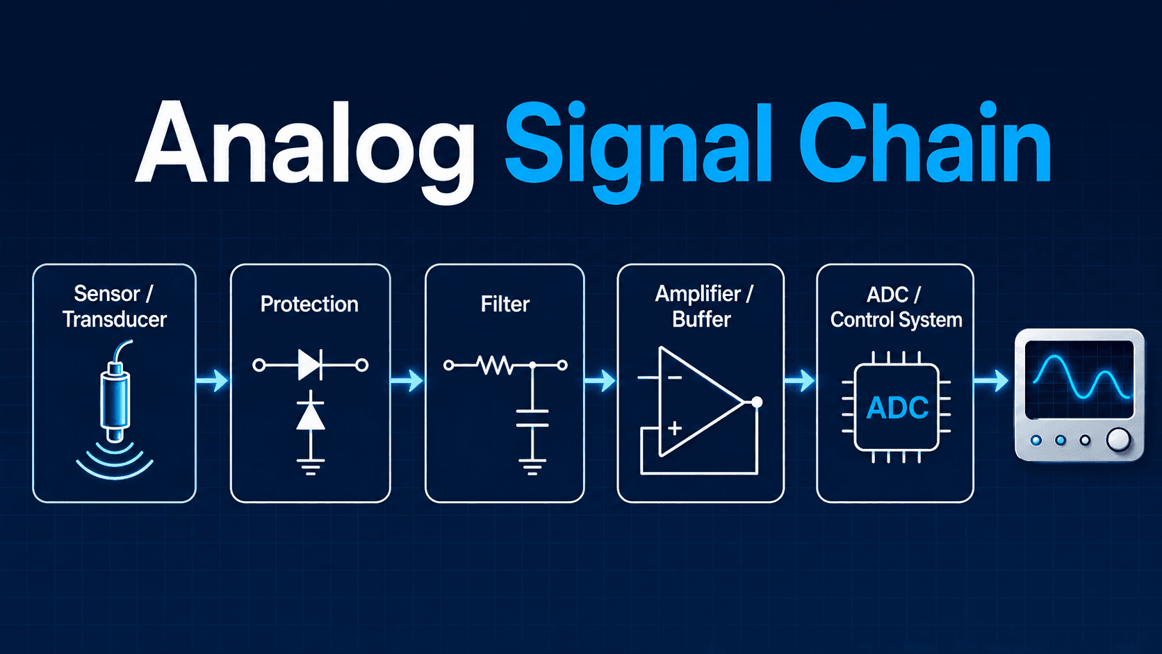
The key idea is that the signal is not simply “read” by a digital device. It often needs analog protection, filtering, scaling, buffering, and conversion before it can be trusted.
What Is Analog Electronics?
Analog electronics focuses on circuits where the electrical signal can vary continuously over a range of values. A microphone voltage, a thermistor signal, a current transformer output, and an op-amp output are all examples of analog behavior because their values can move smoothly rather than jumping only between logic states.
In engineering practice, analog electronics is less about one specific component and more about signal behavior. A circuit may be designed to reduce noise, scale a voltage, isolate a dangerous input, amplify a weak sensor signal, smooth ripple, regulate a supply, or preserve waveform shape before another system uses the information.
Analog electronics is the real-world interface layer of many electrical systems. Digital processors are powerful, but they usually need analog front-end circuits to make physical measurements safe, stable, and meaningful.
Analog Electronics vs Digital Electronics
The simplest difference is that analog electronics represents information with a continuously variable signal, while digital electronics represents information with discrete states. A smooth waveform can represent many values over time, while a digital waveform is interpreted as logic levels such as high and low.
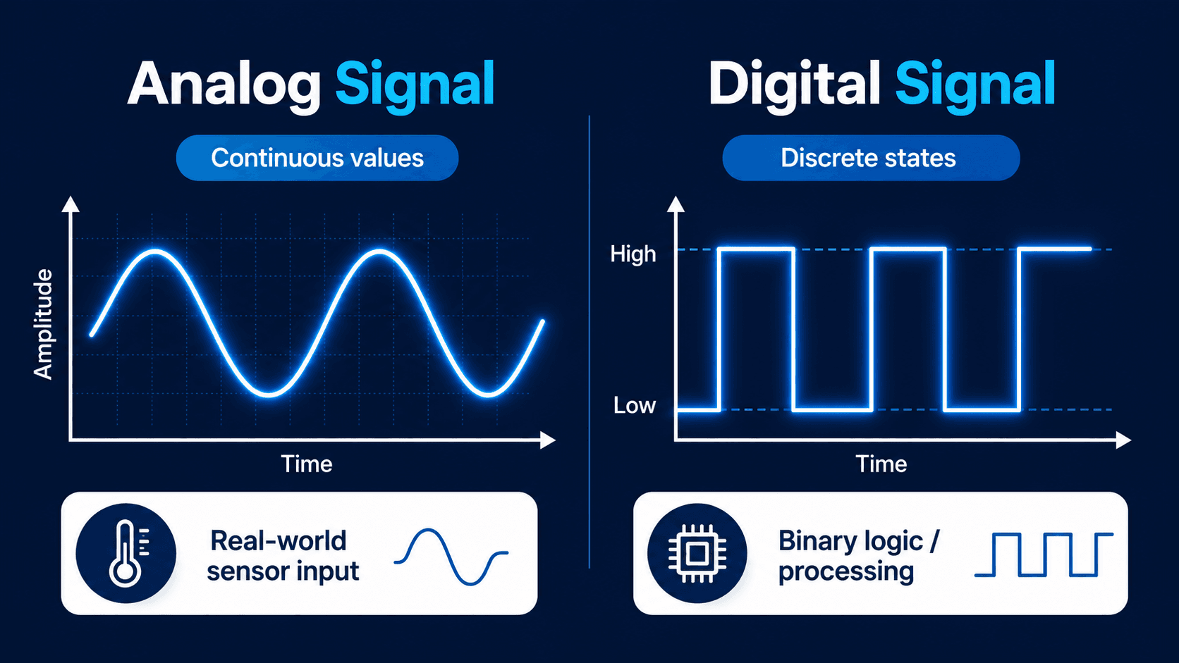
Digital circuits are still physical electrical circuits, so their logic states are ultimately represented by voltages and currents. The difference is that digital hardware uses thresholds to decide whether a signal is interpreted as a logic high or logic low, while analog electronics cares about the actual value and shape of the signal.
| Comparison point | Analog electronics | Digital electronics |
|---|---|---|
| Signal representation | Uses continuously varying voltage or current. | Uses discrete logic states such as 0 and 1. |
| Typical job | Senses, filters, amplifies, regulates, and conditions real-world signals. | Computes, stores, communicates, and makes logic-based decisions. |
| Common weakness | More sensitive to noise, drift, tolerance, grounding, and loading effects. | Needs defined thresholds and may lose detail during sampling or quantization. |
| Where they meet | Analog front ends prepare the signal before conversion. | ADCs, DACs, microcontrollers, relays, and digital controllers use the conditioned signal. |
Analog Electronics Components and What They Do
A useful way to learn analog electronics is to connect each component to the job it performs in a signal path. The same resistor or capacitor can appear in many circuits, but its engineering purpose changes depending on whether the circuit is scaling a signal, filtering noise, biasing a transistor, protecting an input, or setting timing behavior.
| Component or circuit block | Analog function | Engineering implication |
|---|---|---|
| Resistor | Limits current, sets bias, divides voltage, and creates feedback ratios. | Resistance value, tolerance, power rating, and loading determine whether the signal is scaled accurately. |
| Capacitor | Stores charge, blocks DC, passes AC, smooths ripple, and forms filters. | Capacitance, voltage rating, leakage, ESR, and dielectric behavior affect timing and noise performance. |
| Inductor | Stores energy in a magnetic field and resists rapid changes in current. | Inductance, saturation current, winding resistance, and core losses matter in filters and power circuits. |
| Diode | Controls current direction, clamps voltage, rectifies AC, and protects inputs. | Forward voltage, reverse rating, speed, and surge capability affect rectifier and protection behavior. |
| Transistor | Amplifies signals, switches current, regulates outputs, and buffers loads. | Biasing, thermal behavior, gain variation, and safe operating area affect reliability. |
| Operational amplifier | Amplifies, buffers, filters, compares, sums, integrates, or conditions signals. | Supply rails, input range, output swing, offset, bandwidth, and slew rate determine whether the op-amp behaves as intended. |
| Sensor or transducer | Converts a physical quantity into an electrical signal. | Weak sensor signals often need protection, filtering, amplification, and calibration before they are useful. |
For a stronger foundation, review basic electronic components, transistors, and amplifiers as supporting topics.
Common Analog Electronic Circuits and Functions
Most analog circuits can be understood by asking what the circuit is trying to do to the signal. It may not matter whether the schematic looks complex at first; the function is usually one of a few practical engineering jobs.
| Analog circuit type | What it does | Where it appears | What can go wrong |
|---|---|---|---|
| Voltage divider | Scales a voltage to a smaller level. | Sensor inputs, ADC scaling, reference circuits, measurement interfaces. | The load can change the divider ratio if input impedance is too low. |
| RC filter | Passes or attenuates signals based on frequency. | Noise reduction, anti-aliasing, smoothing, timing circuits. | The filter can slow the signal or remove useful high-frequency information. |
| Op-amp amplifier | Increases a weak signal using feedback-controlled gain. | Instrumentation, sensors, audio, control feedback, measurement systems. | The amplifier can saturate, oscillate, or distort if bandwidth and supply rails are ignored. |
| Op-amp buffer | Provides high input impedance and low output impedance. | Sensor isolation, voltage followers, ADC drivers, reference buffers. | The buffer may still be limited by input range, output current, or stability with capacitive loads. |
| Comparator | Compares an analog signal to a threshold. | Limit detection, protection logic, zero-crossing detection, simple control circuits. | Noise near the threshold can cause chatter unless hysteresis or filtering is used. |
| Rectifier | Converts alternating current behavior into one-direction current flow. | Power supplies, detection circuits, AC measurement front ends. | Diode drop, heating, reverse rating, and ripple can affect performance. |
| Voltage regulator | Maintains a stable voltage under load and input variation. | Analog supplies, sensor rails, op-amp rails, embedded electronics. | Dropout, heat, transient response, and output capacitor selection can cause instability. |
| Oscillator | Creates a periodic waveform. | Timing, signal generation, modulation, test circuits. | Frequency drift, startup problems, and loading can shift the output waveform. |
Why Impedance Matters in Analog Electronics
Impedance is one of the most important practical ideas in analog electronics because every circuit stage interacts with the stage before and after it. A sensor, divider, filter, amplifier, cable, oscilloscope probe, or ADC input can change the signal if the impedance relationship is not considered.
In simple terms, source impedance describes how strongly a signal source can drive the next stage. Load impedance describes how much the receiving stage draws from the source. Input impedance and output impedance determine whether the signal is transferred accurately or distorted by loading.
| Impedance issue | What it means in practice | Common engineering response |
|---|---|---|
| High source impedance | The signal can be easily disturbed by load current, leakage, cable capacitance, or measurement equipment. | Use a buffer, shorten the signal path, reduce leakage, or choose a higher input impedance stage. |
| Low input impedance | The receiving circuit pulls current and changes the signal level. | Check divider loading, ADC input behavior, and sensor output capability. |
| Capacitive loading | Cables and inputs can slow a signal or destabilize an amplifier. | Add isolation resistance, use a stable driver, or redesign the filter/input stage. |
| Measurement loading | A probe or meter changes the circuit being measured. | Use proper probe settings and understand meter/probe input impedance. |
Many analog troubleshooting problems are really impedance problems. If the signal looks correct when disconnected but wrong when connected, loading should be one of the first checks.
Where ADCs and DACs Fit
Analog electronics often connects the physical world to digital systems. An analog-to-digital converter, or ADC, samples an analog voltage and represents it as a digital number. A digital-to-analog converter, or DAC, takes a digital value and produces an analog voltage or current.
The analog circuit before an ADC is often called the analog front end. Its job is to make the signal safe, stable, scaled, filtered, and low-noise enough for the converter to interpret correctly.
| ADC/DAC concept | Why it matters | Analog design implication |
|---|---|---|
| Input range | The ADC can only measure within its allowed voltage range. | Analog scaling and protection must prevent overvoltage and clipping. |
| Resolution | The number of bits controls the smallest digital step size. | Noise and offset should be low enough that useful detail is not lost. |
| Sampling rate | The ADC captures the signal at discrete time intervals. | Filtering may be needed before sampling to reduce aliasing and high-frequency noise. |
| Reference voltage | The converter uses a reference to define measurement scale. | A noisy or drifting reference can create measurement error even if the sensor is stable. |
| DAC output drive | A DAC output may not be able to drive the final load directly. | Buffers, filters, and output protection may be required. |
Applications of Analog Electronics
Analog electronics appears anywhere a continuously changing signal must be sensed, shaped, controlled, or delivered. Even when the final system is digital, the front end, power supply, sensor interface, or output driver is often analog.
| Application area | Analog electronics role | Typical design concern |
|---|---|---|
| Sensors and instrumentation | Conditions weak signals from temperature, pressure, light, vibration, or current sensors. | Noise, calibration, offset, impedance, and input protection. |
| Audio systems | Amplifies, filters, mixes, and drives continuous audio waveforms. | Distortion, bandwidth, noise floor, power supply rejection, and clipping. |
| Power supplies | Rectifies, filters, regulates, and protects voltage rails. | Ripple, heat, transient response, stability, and load regulation. |
| RF and communications | Handles high-frequency amplification, filtering, mixing, and tuning. | Bandwidth, impedance matching, noise figure, and layout parasitics. |
| Industrial controls | Interfaces sensors, actuators, feedback loops, and control inputs. | Isolation, electrical noise, cable length, grounding, and fault tolerance. |
| Medical and test equipment | Measures small signals and converts them into reliable displayed or recorded values. | Precision, leakage, filtering, safety isolation, and measurement accuracy. |
| Power system monitoring | Measures and conditions voltage and current signals for metering, protection, and control. | Isolation, scaling, transient protection, filtering, and ADC-ready signal levels. |
Analog Electronics in Power Systems Engineering
One important application is power systems engineering, where analog electronics conditions voltage and current signals before metering, protection, or control equipment uses them. The power system may be high voltage and high current, but the electronics usually needs a lower, isolated, conditioned signal that safely represents the measured quantity.
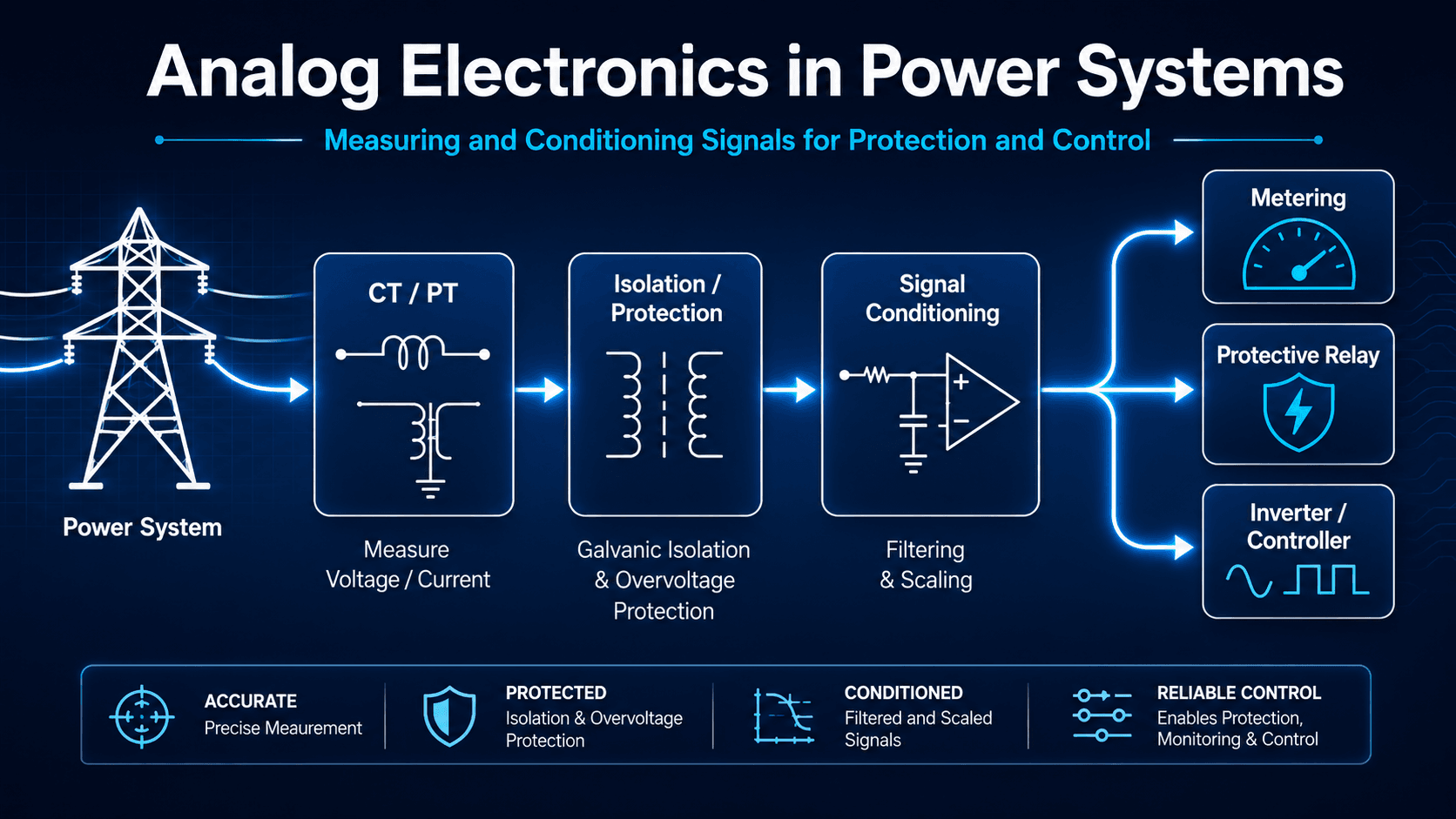
- Metering: Analog front ends scale voltage and current signals before measurement and energy calculations.
- Protective relays: CT and PT signals are conditioned so relay logic can detect faults, abnormal current, voltage disturbances, or phase-related issues.
- Inverter and converter controls: Analog sensing helps controllers observe current, DC bus voltage, AC output voltage, temperature, and feedback signals.
- Power supplies: Rectifiers, filters, regulators, feedback loops, and protection circuits are all analog building blocks.
- Monitoring systems: Field measurements often require isolation, surge protection, filtering, and ADC-ready scaling.
The analog circuit does not need to carry the full power-system energy to be critical. A low-energy conditioned signal can drive metering accuracy, protection dependability, alarm logic, and controller response.
Basic Analog Electronics Equations and Design Checks
Analog electronics can become mathematically deep, but many practical checks start with a few first-principles relationships. These equations help engineers estimate signal levels, gain, filtering behavior, and whether a circuit is likely to overload, clip, or distort the signal.
Voltage divider scaling
A voltage divider is one of the simplest analog signal-scaling circuits. It is useful when the load is high impedance and the divider current, power, and accuracy are acceptable.
Amplifier gain
Gain compares output signal amplitude to input signal amplitude. A high gain value is only useful if the amplifier has enough bandwidth, supply voltage, output swing, and stability margin.
First-order RC low-pass cutoff frequency
A first-order RC filter is commonly used to reduce high-frequency noise, but it also slows the signal response. The cutoff frequency is a starting point, not a complete noise analysis. In real circuits, the effective resistance and capacitance may change when source impedance, load impedance, ADC input behavior, or op-amp input behavior is included.
- \(V_{in}\) Input voltage before scaling, amplification, or filtering.
- \(V_{out}\) Output voltage delivered to the next stage, controller, meter, or ADC input.
- \(R\) Resistance in ohms; affects current, loading, gain ratios, and filter behavior.
- \(C\) Capacitance in farads; affects timing, smoothing, coupling, and frequency response.
- \(f_c\) Cutoff frequency in hertz; a practical reference point for first-order filter behavior.
For practical circuit calculations, the Voltage Divider Calculator and Current Divider Calculator can help connect these relationships to actual component values.
Worked Example: Conditioning a 0–10 V Sensor Signal for a 3.3 V ADC
A practical analog electronics task is taking a real-world sensor signal and making it safe for a digital controller. Suppose a sensor outputs 0–10 V, but the ADC input on a controller accepts only 0–3.3 V. The analog front end must scale the signal, protect the input, reduce noise, and avoid loading errors.
Step 1: Scale the voltage
The target ratio is \(3.3/10=0.33\). A divider can be selected so that \(R_2/(R_1+R_2)\) is approximately 0.33. For example, \(R_1=20\,k\Omega\) and \(R_2=10\,k\Omega\) gives:
Step 2: Check loading and ADC behavior
The divider result is only reliable if the ADC input does not significantly load the divider. If the ADC input impedance is not high enough, or if the ADC sampling capacitor creates transient current demand, a buffer amplifier may be needed between the divider and ADC.
Step 3: Add filtering and protection
A small RC filter can reduce high-frequency noise before the ADC input, but the cutoff frequency must be high enough to preserve the signal changes the controller actually needs. Input protection may also be needed so wiring faults, surges, or abnormal sensor outputs do not damage the ADC.
The divider equation is only the first step. A complete analog design also checks impedance, ADC input range, fault protection, noise, filter delay, component tolerance, and whether the output can be tested without disturbing the signal.
Senior Engineer Review Checklist for Analog Circuits
A good analog circuit review does not stop at whether the schematic is mathematically correct. It asks whether the signal remains valid across component tolerance, temperature, source conditions, loading, faults, noise, and the limits of the next device in the chain.
Start with the physical signal, identify the expected minimum and maximum range, protect the input, filter only what should be removed, set the gain or scaling, check the receiving device limits, then confirm the circuit can be measured and tested under realistic conditions.
| Analog design check | What to look for | Why it matters |
|---|---|---|
| Signal range | Minimum, normal, maximum, transient, and fault-level input values. | The circuit must not clip, saturate, or exceed device ratings during expected operation. |
| Source and load impedance | Whether the next stage pulls enough current to change the signal value. | Loading can make a correct-looking voltage divider or sensor circuit produce the wrong output. |
| Bandwidth | Signal frequency content, filter cutoff, amplifier bandwidth, and response time. | A circuit can pass DC accurately but distort fast-changing signals or transients. |
| Noise margin | Noise sources, shielding, grounding, cable length, and filter placement. | Weak analog signals can be buried by electrical noise before they reach the controller. |
| Supply rails | Available positive and negative rails, input common-mode range, and output swing. | Op-amps and comparators cannot output voltages beyond their practical supply limits. |
| Thermal behavior | Power dissipation, drift, self-heating, ambient temperature, and component ratings. | Analog accuracy can shift as temperature changes, especially in sensors and precision dividers. |
| Protection | Input clamps, surge protection, isolation, fusing, and reverse polarity behavior. | Field wiring errors or transient events can destroy sensitive analog front-end circuits. |
| Testability | Probe points, expected voltage ranges, calibration points, and safe measurement locations. | Technicians need a reliable way to verify the circuit without disturbing the signal. |
How to Learn Analog Electronics in the Right Order
Analog electronics is easier to learn when each topic builds on the previous one. Jumping directly into op-amps, filters, or transistor biasing without understanding basic voltage, current, resistance, capacitance, and measurement behavior usually leads to confusion.
| Learning step | What to understand | Why it matters for analog electronics |
|---|---|---|
| 1. Circuit fundamentals | Voltage, current, resistance, Ohm’s law, series and parallel circuits. | These define how signals and currents move through every analog circuit. |
| 2. Passive components | Resistors, capacitors, inductors, impedance, and time constants. | Passive components control scaling, filtering, timing, and energy storage. |
| 3. Diodes and rectifiers | Forward voltage, reverse blocking, clamps, rectification, and protection. | Diodes shape current flow and protect sensitive analog inputs. |
| 4. Transistors | Biasing, switching, amplification, thermal behavior, and load control. | Transistors are core active devices in amplifiers, regulators, and drivers. |
| 5. Op-amps and feedback | Gain, buffers, input range, output swing, bandwidth, and stability. | Op-amps are central to signal conditioning, filtering, and precision analog design. |
| 6. Filters and frequency response | Low-pass, high-pass, bandwidth, cutoff frequency, noise, and delay. | Filtering controls what part of a signal is preserved or rejected. |
| 7. Signal conditioning | Protection, isolation, scaling, buffering, ADC input requirements, and calibration. | This connects analog circuits to real sensors, meters, controllers, and field devices. |
| 8. Simulation and bench testing | SPICE models, oscilloscopes, function generators, multimeters, and power supplies. | Analog behavior must be verified because real circuits rarely match ideal assumptions perfectly. |
Engineering Judgment and Field Reality
Analog electronics is where ideal circuit theory meets imperfect physical behavior. Real components have tolerance, temperature drift, parasitic capacitance, leakage, inductance, finite bandwidth, offset voltage, input bias current, and package limitations. Wiring and layout also matter because a long cable, poor ground path, or nearby switching device can change what the circuit actually sees.
The most important field judgment is deciding which details are worth controlling. A student problem may assume an ideal op-amp or exact resistor values. A real design must decide whether a 1% resistor is good enough, whether the ADC input needs buffering, whether the filter delay is acceptable, and whether the circuit will survive abnormal voltage or current.
Analog problems are often diagnosed by comparing the expected waveform to the measured waveform. A multimeter may confirm a DC value, but an oscilloscope often reveals ripple, clipping, oscillation, noise, delayed response, or unstable behavior that a static reading hides.
When This Breaks Down
The simplified analog electronics model breaks down when the circuit is treated as ideal. Continuous signals are powerful because they can represent real physical behavior, but that also means they are exposed to noise, interference, nonlinearity, thermal effects, and the limits of physical devices.
- The input exceeds the circuit range: The signal clips, saturates, or damages an input stage.
- The source is loaded by the next stage: A sensor or divider output changes because the receiving circuit draws too much current.
- The filter removes useful information: A low cutoff frequency may reduce noise but also delay or attenuate real signal changes.
- The amplifier is too slow: Limited bandwidth or slew rate can distort fast signals even when the DC gain is correct.
- Grounding is poor: Ground loops, shared return paths, and electromagnetic interference can create false readings.
- The design ignores tolerances: Resistor, capacitor, sensor, and op-amp variations can shift the real operating point away from the nominal calculation.
Do not assume that an analog circuit is correct just because the schematic equation is correct. The next-stage load, input limits, noise environment, and component tolerances can change the result.
Common Misconceptions About Analog Electronics
Analog electronics is often oversimplified as “old electronics” or treated as separate from digital systems. In reality, modern electrical systems often depend on analog circuits precisely because physical measurements, power supplies, and real-world interfaces are not purely digital.
| Misconception | Reality | Practical takeaway |
|---|---|---|
| Analog electronics is obsolete. | Modern digital systems still rely on analog front ends, power supplies, sensors, and signal conditioning. | Analog knowledge remains important for measurement, protection, control, and hardware troubleshooting. |
| Analog means inaccurate. | Analog circuits can be extremely precise when designed with proper references, layout, components, and calibration. | Accuracy depends on design details, not whether the signal is analog or digital. |
| Op-amps behave like ideal textbook blocks. | Real op-amps have input range, output swing, offset, noise, bandwidth, slew-rate, and stability limits. | Always check the datasheet against the signal range and frequency content. |
| A voltage divider can power a load. | Voltage dividers are usually for signal scaling, not supplying power to changing loads. | Use a regulator, buffer, or proper power stage when the load current matters. |
| Filtering noise always improves the circuit. | A filter can also delay the response or remove real signal content. | Choose the cutoff frequency based on both noise rejection and the signal dynamics you need to preserve. |
Useful References and Design Context
Analog electronics is usually learned through a mix of circuit theory, lab work, simulation, measurement, and component datasheets. For deeper structured learning, an authoritative technical education source is more useful than a short definition page.
- Analog Devices University resources: Analog Devices University analog electronics tutorials provide practical educational material on op-amps, instrumentation amplifiers, analog switches, voltage references, and related analog circuit topics.
- Project-specific criteria: Final analog circuit design may also depend on owner requirements, device datasheets, equipment manuals, safety requirements, EMI environment, and site-specific operating conditions.
- Engineering use: Engineers typically combine first-principles checks, simulation, bench testing, datasheet review, and field measurement to confirm that an analog circuit performs reliably outside ideal textbook assumptions.
Frequently Asked Questions
Analog electronics is the part of electronics that works with continuously changing voltages and currents. Instead of only using two states like a digital circuit, an analog circuit can represent many values across time, which makes it useful for sensors, amplifiers, filters, power supplies, metering, and control inputs.
Analog electronics represents information with continuous signal levels, while digital electronics represents information with discrete states such as logic high and logic low. In practice, many systems use both: analog circuits measure and condition real-world signals, and digital circuits process, store, or communicate the resulting information.
Common analog electronics components include resistors, capacitors, inductors, diodes, transistors, operational amplifiers, sensors, transformers, and regulators. The important point is not just the component list, but the function each component performs, such as scaling voltage, limiting current, filtering noise, amplifying weak signals, isolating circuits, or stabilizing a supply.
Yes. Analog electronics is still important because real-world quantities such as voltage, current, temperature, light, vibration, sound, pressure, and magnetic fields are naturally continuous. Even digital systems often need analog front-end circuits to protect inputs, filter noise, amplify weak signals, and convert physical measurements into usable electrical information.
In power systems, analog electronics is used to measure and condition voltage and current signals before they are used by meters, protective relays, controllers, inverters, or monitoring equipment. Typical functions include CT and PT interfacing, isolation, filtering, scaling, surge protection, signal buffering, and conversion into a form that digital equipment can safely read.
Summary and Next Steps
Analog electronics is the engineering discipline behind continuous electrical signals. It explains how circuits sense real physical quantities, protect inputs, filter noise, amplify weak signals, regulate supplies, convert between analog and digital domains, and prepare measurements for control or digital processing.
The practical skill is not just recognizing components. It is understanding the signal chain: what the signal represents, how large it can become, what noise or faults it may see, how it is scaled or buffered, and whether the next stage can use it accurately.
Where to go next
Continue your learning path with related Turn2Engineering resources.
-
Basic Electronic Components
Learn the core parts used to build analog circuits, including resistors, capacitors, inductors, diodes, transistors, and integrated circuits.
-
Amplifiers
Go deeper into one of the most important analog circuit functions: increasing signal level without losing useful information.
-
Circuit Simulation
See how simulation tools help predict voltage, current, gain, filtering, and circuit behavior before physical testing.