Key Takeaways
- Definition: The shear stress equation finds average stress acting parallel to a resisting plane by dividing shear force by effective area.
- Main use: Engineers use it for quick checks of bolts, pins, rivets, lap joints, plates, weld groups, and other members that may fail by sliding.
- Watch for: The biggest errors usually come from choosing the wrong resisting area, forgetting the number of shear planes, or mixing units.
- Outcome: After this page, you should be able to solve for shear stress, force, or required area and know when the simple equation stops being enough.
Table of Contents
Reading the average shear stress diagram
The shear stress equation relates force acting parallel to a resisting area, helping engineers estimate average sliding stress in bolts, pins, plates, and joints.
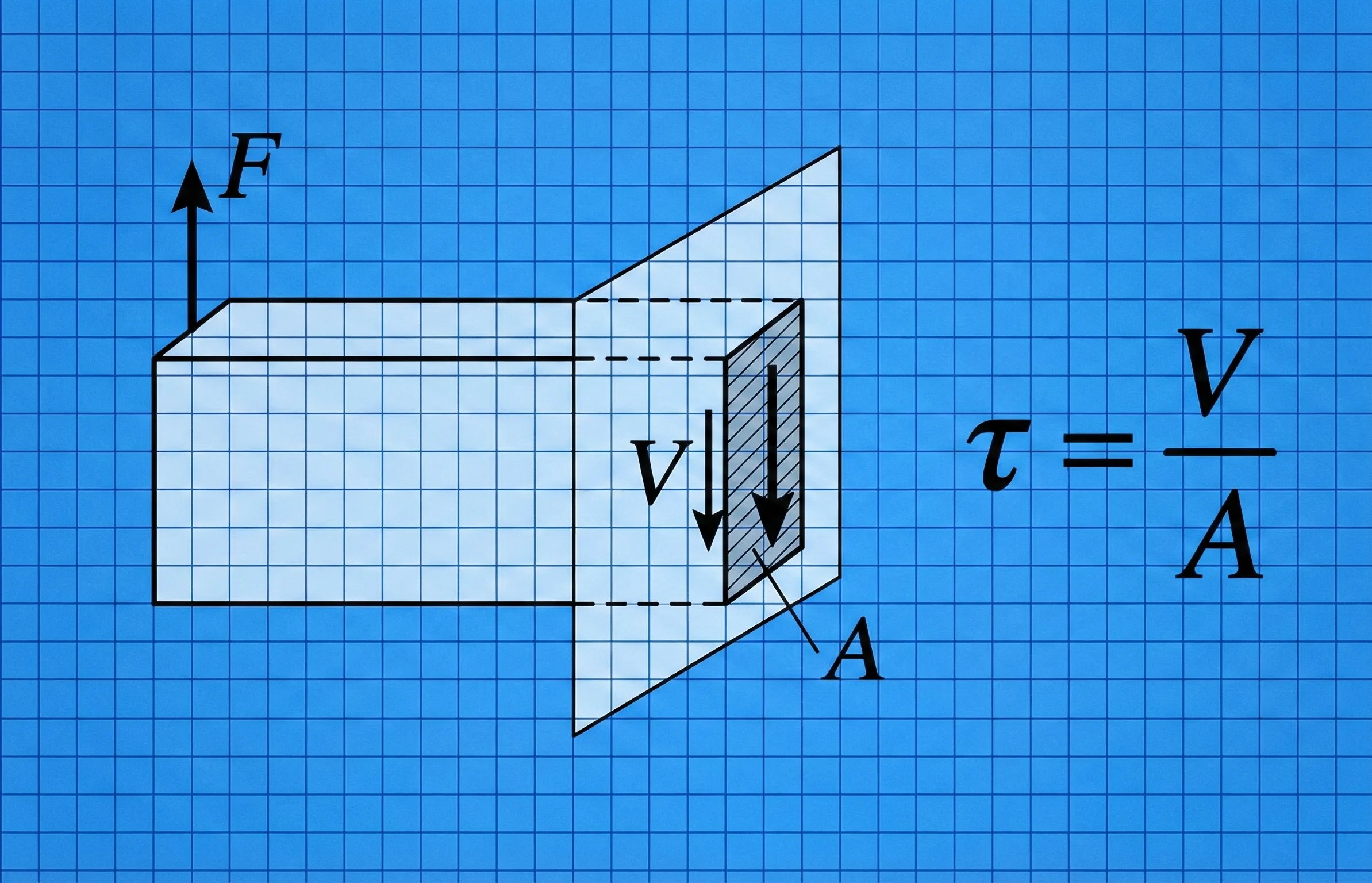
Notice the two ideas first: the force is parallel to the section, not perpendicular to it, and the shaded area is the plane resisting that sliding action. That is why the equation is so compact. It is a force-over-area relationship, but for parallel loading rather than normal tension or compression.
What is the shear stress equation?
The shear stress equation is the standard average-stress relationship used when a force tries to make one part of a material or connection slide past another. In its most common form, it is written as \( \tau = \dfrac{V}{A} \), where \( \tau \) is average shear stress, \( V \) is the shear force carried across the plane, and \( A \) is the effective resisting area.
Engineers use this equation because it gives a fast first-pass check. It helps answer questions such as: Is a bolt overstressed in shear? Is a pin in a clevis likely to fail? Does a connection detail have enough effective area to carry the applied load? On exams it is often introduced as a simple mechanics-of-materials formula, but in practice it also acts as a screening tool before you move into more detailed connection design, stress distribution analysis, or code checks.
The word average matters. Real shear stress distributions are not always uniform. The equation is still extremely useful, but good engineering judgment requires knowing whether a uniform average is appropriate or whether a more advanced model is needed.
The shear stress formula
For most introductory and connection-level problems, the primary form is the average shear-stress equation below.
Physically, this says the stress rises when the shear force increases and falls when the resisting area increases. Double the load while holding area constant, and the average shear stress doubles. Double the effective resisting area while holding load constant, and the average shear stress is cut in half.
A very common variation appears when more than one shear plane shares the load.
Here, \( n \) is the number of equal shear planes. This is how many fastener problems are handled when distinguishing between single shear and double shear. If a pin is in double shear and load sharing is reasonably even, the effective resisting area is doubled.
Variables and units
The equation is short, but each symbol must be interpreted correctly. The force must be the shear force on the plane of interest, and the area must be the area actually resisting sliding on that plane.
- \( \tau \) Average shear stress, usually reported in Pa, kPa, MPa, psi, or ksi.
- \( V \) Shear force acting parallel to the resisting plane, often in N, kN, lb, or kip.
- \( A \) Effective resisting area on the shear plane, commonly in \(m^2\), \(mm^2\), or \(in^2\).
- \( n \) Number of equal shear planes when the load is shared by more than one plane.
In SI, \(1\ \text{N/mm}^2 = 1\ \text{MPa}\). That makes \(N\) and \(mm^2\) a very convenient combination for mechanical and structural connection checks.
Stress units must always reduce to force divided by area. If your final units do not collapse to Pa, MPa, psi, or ksi, the setup or conversion is wrong.
| Variable | Meaning | SI units | US customary units | Typical use | Notes |
|---|---|---|---|---|---|
| \( \tau \) | Average shear stress | Pa, kPa, MPa | psi, ksi | Demand on a connection or section | Acts parallel to the plane, not normal to it. |
| \( V \) | Shear force | N, kN | lb, kip | Applied or transferred load | Use the force carried by the specific plane being checked. |
| \( A \) | Effective resisting area | \(m^2\), \(mm^2\) | \(in^2\) | Area resisting sliding | Wrong area selection is one of the most common mistakes. |
| \( n \) | Number of shear planes | — | — | Single vs. double shear | Only use when the load sharing assumption is defensible. |
How to rearrange the shear stress equation
In design work, engineers often do not solve for stress first. Just as often, they know an allowable shear stress and need the required area, or they know the area and want the maximum force that can be carried. The two most useful rearrangements are shown below.
These are especially useful in early sizing. For example, if you know the design shear force and the allowable average shear stress, the required area follows directly from \( A = \dfrac{V}{\tau} \). If the area comes from an existing pin, bolt shank, plate width, or weld throat, the stress follows from the original form.
After rearranging, confirm that the answer makes physical sense. Required area should increase as load increases, and allowable force should increase as either area or allowable stress increases. If your algebra predicts the opposite, the rearrangement is wrong.
Worked example
Example problem — steel pin in double shear
A steel pin with diameter \(d = 12\ \text{mm}\) carries a total transverse load of \(18\ \text{kN}\) in a clevis connection. Assume the pin is in double shear and the load is shared equally by two shear planes. Find the average shear stress in the pin.
First, calculate the area of one circular shear plane:
Because the pin is in double shear, the total effective resisting area is:
Now substitute into the average shear-stress equation:
The average shear stress in the pin is \(79.6\ \text{MPa}\). Because \(1\ \text{N/mm}^2 = 1\ \text{MPa}\), the unit conversion is immediate. In a real design, the next step would be to compare that demand to the allowable or design shear strength of the pin material and then check related failure modes such as bearing, tear-out, or block shear in the connected plates.
A result can be numerically correct but still incomplete. Connection design rarely ends with one stress check. The fastener, connected material, edge distances, and deformation limits may control before average pin shear does.
Shear stress equation vs. related equations
Many readers searching for the shear stress equation are actually dealing with one of three different situations: average shear on a plane, shear stress caused by torsion, or stress transformation in a combined stress state. The table below helps separate those use cases.
| Equation / method | Best used for | Key assumption | Main limitation |
|---|---|---|---|
| \( \tau = \dfrac{V}{A} \) | Average shear in pins, bolts, plates, lap joints, and simple connection checks | Load is represented as an average over a resisting plane | Does not show nonuniform local stress distribution |
| \( \tau = \dfrac{Tr}{J} \) | Torsional shear stress in circular shafts | Cross section and torsion theory are appropriate | Not a substitute for average connection shear |
| Mohr’s Circle / stress transformation | Finding principal stresses and maximum in-plane shear from combined stress states | Known plane stress components at a point | More analysis-heavy than a simple force-over-area check |
| \( \tau = G\gamma \) | Elastic relation between shear stress and shear strain | Linear elastic behavior | Describes deformation response, not just force transfer |
Assumptions behind the equation
The average shear-stress equation is powerful because it is simple, but that simplicity comes from assumptions. The more closely your problem matches these assumptions, the more reliable the result becomes as a design check or screening calculation.
- 1 The force acts primarily parallel to the plane being checked.
- 2 The resisting area has been identified correctly and is the area actually carrying the shear.
- 3 Average stress is an acceptable representation of the problem, even if local peaks exist.
- 4 If multiple shear planes are used, the load sharing between them is reasonably equal.
Neglected factors
This equation usually ignores several effects that can become important in real engineering details:
- Stress concentrations: Holes, fillets, notches, and load-introduction regions can create local peak stresses well above the average value.
- Combined loading: Many members see shear plus bearing, bending, tension, torsion, or fatigue at the same time.
- Nonuniform stress distribution: In beams, weld groups, adhesive joints, and complex connections, the true shear distribution may not be uniform.
- Material and connection behavior: Ductility, slip, preload, fracture mode, and local deformation can change what actually controls.
Engineering judgment and field reality
In the field, the hardest part of a shear-stress check is often not the algebra. It is deciding what the real load path is and what area is genuinely resisting that load. A clean textbook sketch might show one obvious shear plane, but actual details can include eccentricity, looseness, hole clearance, misalignment, prying, uneven plate fit-up, or installation tolerances that shift how the force is transferred.
If a connection looks like it could rotate, bear unevenly, or pick up bending in the fastener, do not assume the simple average shear equation is the full answer. Use it as a first check, then review the actual failure modes.
Before trusting the result, ask two questions: “Did I use the correct shear plane?” and “Would a senior engineer looking at the detail agree that this area really carries the load?” Those two checks catch many mistakes faster than redoing the arithmetic.
When this equation breaks down
The equation \( \tau = \dfrac{V}{A} \) is not a universal shear model. It becomes less reliable when the stress field is strongly nonuniform, when deformation compatibility matters, or when the real failure mode is not simple sliding along a well-defined plane.
Do not rely on average shear stress alone when torsion controls, when beam shear distribution matters, when fracture patterns are complex, or when design codes require more specific connection checks than simple force-over-area screening.
This is why many practical problems move quickly from the simple equation to more specialized methods. Shaft torsion problems use torsional shear relations. Combined stress problems often use stress-transformation equations or Mohr’s Circle. Structural and mechanical connection details may require code-based limit-state checks instead of a single average-stress calculation.
Common mistakes and engineering checks
- Using the gross area when the actual shear plane passes through a smaller net section.
- Forgetting to distinguish between single shear and double shear.
- Mixing N with \(m^2\), or lb with \(mm^2\), without converting units properly.
- Treating average shear stress as though it were the exact stress everywhere in the part.
- Checking only fastener shear when bearing, tear-out, fracture, or plate yielding may also control.
If the result seems surprisingly low, verify that you did not accidentally use too much resisting area. If it seems surprisingly high, verify that you did not forget an additional shear plane or mis-handle the load units.
| Check item | What to verify | Why it matters |
|---|---|---|
| Units | Force and area belong to one consistent unit system | Bad unit pairs create meaningless stress values |
| Shear planes | Single, double, or multiple shear has been identified correctly | This directly changes the effective resisting area |
| Area choice | The area matches the actual plane resisting sliding | Wrong area selection is a major source of design error |
| Failure mode | Average shear is actually the relevant demand to check | Other modes may govern before simple shear does |
Frequently asked questions
The shear stress equation is \( \tau = \dfrac{V}{A} \). It gives the average stress acting parallel to a resisting plane by dividing the shear force by the effective area carrying that force.
Use consistent force and area units. In SI, \(N/m^2\) gives Pa and \(N/mm^2\) gives MPa. In US customary units, \(lb/in^2\) gives psi and \(kip/in^2\) gives ksi.
In double shear, two planes resist the load. If both planes have the same area and share the force equally, the average shear stress becomes \( \tau = \dfrac{V}{2A} \).
Shear stress is the calculated demand caused by load. Shear strength is the resistance or capacity of the material or connection. Engineering design compares demand to capacity.
It is not enough when stress is strongly nonuniform, when torsion or combined loading controls, when deformation compatibility matters, or when code-based connection limit states must be checked separately.
Summary and next steps
The shear stress equation is one of the fastest and most useful mechanics relationships because it reduces many real engineering checks to a simple force-over-area calculation. Used correctly, it helps you size members, screen connections, and judge whether a detail is broadly reasonable.
The important judgment point is not the arithmetic alone. It is whether the shear plane, resisting area, and load-sharing assumptions truly represent the physical detail you are checking. When those assumptions hold, the equation is excellent. When they do not, it should be treated as a starting point rather than a final answer.
Where to go next
Continue the learning path with these closely related Turn2Engineering resources.
-
Prerequisite: Engineering Equations Hub
Browse the broader mechanics equation set for supporting topics in force, stress, deformation, and energy.
-
Current topic: Shear Stress Equation
Return here when you need the formula, unit guidance, rearrangements, assumptions, and quick engineering checks in one place.
-
Advanced: Mohr’s Circle
Move into stress transformation and maximum in-plane shear when a single average stress value is no longer enough.