Key Takeaways
- Core idea: A heat exchanger transfers heat between fluids at different temperatures, usually through a separating wall so the fluids do not mix.
- Engineering use: Heat exchangers are used in HVAC systems, refrigeration cycles, power plants, process equipment, radiators, condensers, evaporators, and waste heat recovery.
- What controls it: Performance depends on flow rate, temperature difference, heat transfer area, fluid properties, overall heat transfer coefficient, flow arrangement, pressure drop, and fouling.
- Practical check: A heat exchanger that works on paper can still fail in service if cleanability, flow distribution, pressure drop, part-load control, or fouling is ignored.
Table of Contents
Introduction
Heat exchangers are devices that transfer thermal energy between two fluids at different temperatures. In most engineering applications, tubes, plates, coils, or other solid surfaces keep the fluids separated while heat moves from the hotter stream to the colder stream. They matter because they control energy recovery, equipment efficiency, refrigeration performance, process temperature, and thermal safety.
How a Heat Exchanger Transfers Energy
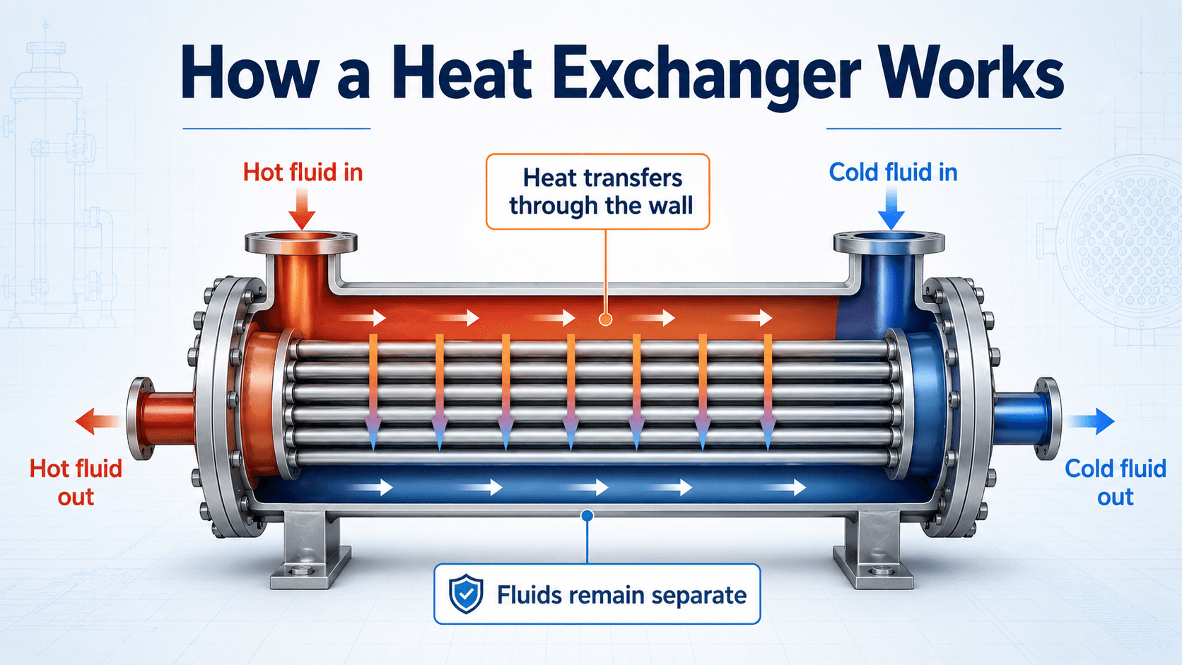
Notice that the exchanger is not creating heat or cold. It is providing controlled surface area so thermal energy can move from one fluid stream to another at a useful rate.
What Is a Heat Exchanger?
Key idea: A heat exchanger is both an energy-balance device and a heat-transfer-rate device.
A heat exchanger is a thermal device that transfers heat between two or more fluids. The fluids may be liquids, gases, vapors, refrigerants, oils, combustion products, steam, process chemicals, or air streams. The most common arrangement keeps the fluids physically separated by a metal wall, tube, coil, or plate while heat flows through that wall.
In thermodynamics, a heat exchanger is usually treated as an open system or control volume. Mass enters and leaves through defined ports, while thermal energy transfers internally from one stream to another. Unlike a turbine or compressor, an ideal heat exchanger does not primarily produce shaft work; its job is to change fluid temperatures, condense vapor, evaporate liquid, recover waste heat, or maintain process conditions.
A basic definition misses the most important engineering point: a heat exchanger must satisfy both the First Law of Thermodynamics and practical heat transfer limits. An energy balance tells how much heat must move, but the exchanger geometry, flow pattern, surface area, and fouling condition determine whether that heat can actually move fast enough.
How Heat Exchangers Work
Key idea: Heat moves because of temperature difference, but the exchanger surface and fluid motion control how fast it moves.
Heat exchangers work because heat naturally moves from a higher-temperature fluid to a lower-temperature fluid. The hot fluid loses energy, the cold fluid gains energy, and the separating surface provides the path for conduction through the wall and convection on both fluid sides. For the underlying physics, review heat transfer, especially conduction through the wall and convection between each fluid and the surface.
Hot side, cold side, and the separating wall
The hot-side fluid enters at a higher temperature and leaves cooler. The cold-side fluid enters at a lower temperature and leaves warmer. The wall between them may be a tube wall, plate wall, coil surface, or finned surface. Heat must pass through several resistances: convection from the hot fluid to the wall, conduction through the wall, and convection from the wall to the cold fluid.
Direct-contact vs indirect-contact heat exchangers
Most heat exchangers discussed in mechanical and thermodynamics courses are indirect-contact exchangers, meaning the fluids are separated by a solid surface. Direct-contact heat exchangers allow the fluids to touch each other directly, such as some cooling towers, spray condensers, quench systems, and gas-liquid contact devices. Direct contact can be effective, but it only works when mixing, contamination, or phase interaction is acceptable.
Heat transfer area is the working surface
The tubes, plates, fins, and shell geometry provide surface area. More area generally gives more opportunity for heat transfer, but it can also increase cost, size, pressure drop, material use, and cleaning difficulty. Good design balances heat duty with hydraulic and maintenance constraints.
Parallel Flow vs Counterflow vs Crossflow Heat Exchangers
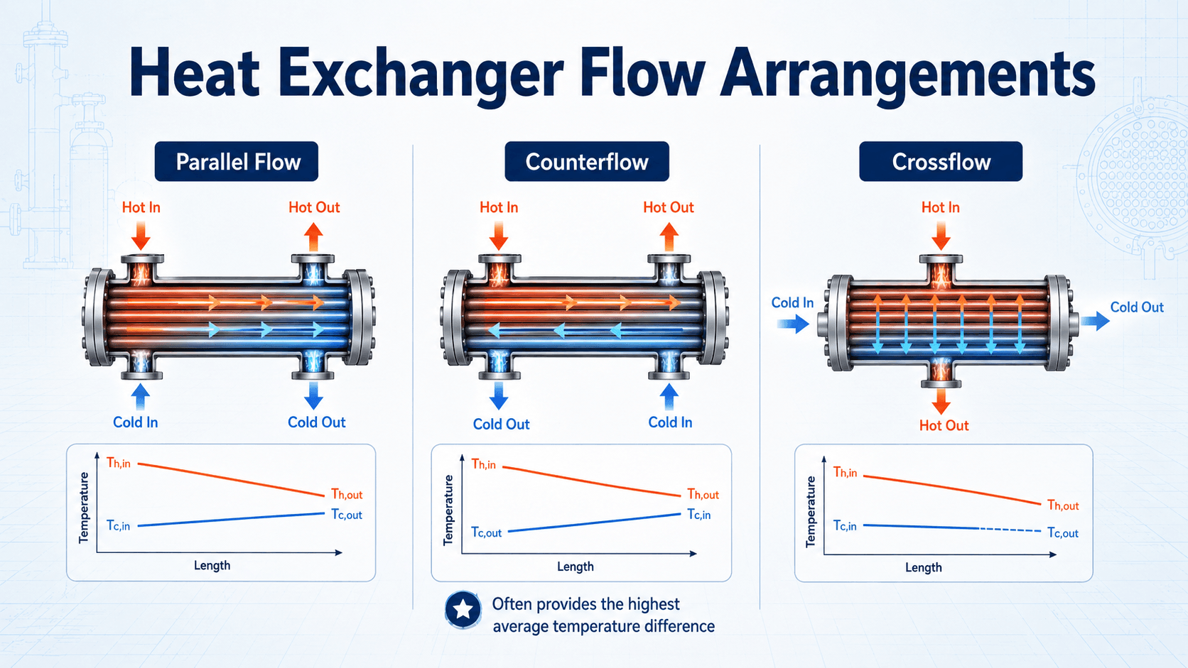
The way the two fluids move relative to each other changes the temperature difference along the exchanger. Parallel flow is simple, but the useful temperature difference drops quickly. Counterflow often maintains a stronger average temperature difference. Crossflow is common when one stream is air or gas moving across a coil or tube bundle.
| Flow arrangement | How the fluids move | Engineering implication |
|---|---|---|
| Parallel flow | Hot and cold streams enter the same end and move in the same direction. | Simple layout, but the temperature difference usually drops quickly along the length. |
| Counterflow | Hot and cold streams enter opposite ends and move in opposite directions. | Often gives a higher average temperature difference and better thermal performance for the same area. |
| Crossflow | One stream moves across the other, commonly air across tubes or fins. | Common in coils, radiators, condensers, and air-side heat transfer equipment. |
| Multipass | One or both fluids make multiple passes through the exchanger. | Can improve compactness or velocity, but may require LMTD correction factors and careful pressure-drop checks. |
Common Heat Exchanger Types
Key idea: “Type” can mean construction, flow arrangement, or function. A strong design decision separates those categories.
Heat exchangers are selected based on pressure, temperature, fluid compatibility, fouling tendency, footprint, cleaning access, heat duty, and allowable pressure drop. The best design is not simply the one with the highest heat transfer rate; it is the one that performs reliably under the actual operating conditions.
| Category | Examples | How to think about it |
|---|---|---|
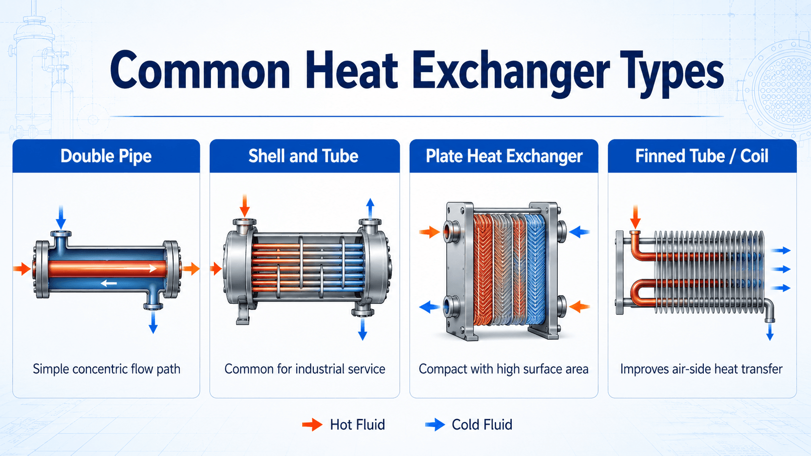
| By construction | Double-pipe, shell-and-tube, plate, spiral, finned-tube | Describes the physical equipment geometry. |
| By flow arrangement | Parallel flow, counterflow, crossflow, multipass | Describes how the hot and cold streams move relative to each other. |
| By function | Heater, cooler, condenser, evaporator, boiler, reboiler, economizer | Describes what the exchanger does in the process or thermodynamic cycle. |
| Heat exchanger type | Best suited for | Main advantage | Common limitation |
|---|---|---|---|
| Double pipe | Small duties, teaching examples, simple liquid-to-liquid exchange | Simple geometry and easy conceptually | Limited area for large heat loads |
| Shell and tube | Industrial service, high pressure, high temperature, process plants | Durable, flexible, and widely maintainable | Larger footprint and more complex mechanical design |
| Plate heat exchanger | Compact liquid-to-liquid exchange and HVAC hydronic systems | High surface area in a small footprint | Gasket, fouling, and pressure limits may control use |
| Finned tube or coil | Air-to-liquid, air-to-refrigerant, HVAC coils, radiators | Improves weak air-side heat transfer | Fins can foul, bend, corrode, or clog |
| Regenerative exchanger | Heat recovery where a storage medium alternately absorbs and releases heat | Can recover energy from cyclic or alternating flows | More complex operation and possible carryover concerns |
Condensers, Evaporators, and Phase-Change Heat Exchangers
Many heat exchangers do more than warm one fluid and cool another. In thermodynamic cycles, they often support phase change. A condenser removes heat from vapor until it becomes liquid. An evaporator adds heat to liquid or liquid-vapor refrigerant until it boils. Boilers and reboilers add heat to generate vapor for power, heating, or process use.
Phase-change exchangers are important because a large amount of heat can move while the fluid temperature changes only slightly. That behavior is central to refrigeration cycles and the vapor compression cycle, where the evaporator absorbs heat at low pressure and the condenser rejects heat at high pressure.
Two-phase heat exchangers require more care than simple liquid-to-liquid exchangers because pressure drop, refrigerant distribution, superheat, subcooling, flooding, dryout, and oil return can control real performance.
Where Heat Exchangers Are Used in Engineering
Heat exchangers appear anywhere a system must control temperature, reject waste heat, recover energy, condense vapor, evaporate liquid, or transfer heat without mixing process streams. They connect thermodynamics to real hardware because they turn temperature differences into useful heat transfer.
- HVAC systems: Coils, chillers, heat recovery ventilators, boilers, condensers, and hydronic loops use exchangers to move heat between air, water, refrigerant, and outdoor conditions.
- Refrigeration and heat pumps: Evaporators absorb heat from a cold space, while condensers reject heat to air or water.
- Power and process plants: Condensers, feedwater heaters, reboilers, economizers, and coolers manage large thermal loads.
- Automotive and electronics cooling: Radiators, oil coolers, intercoolers, cold plates, and liquid loops remove heat from equipment.
- Waste heat recovery: Heat exchangers recover energy from exhaust gases, warm process streams, or rejected heat that would otherwise be lost.
Always identify which side controls performance. In many air coils, the air side dominates because air has a low heat transfer coefficient. In fouling liquid service, the dirty side may dominate because deposits add thermal resistance over time.
Key Factors That Control Heat Exchanger Performance
A heat exchanger is controlled by thermal and hydraulic behavior at the same time. A larger area may improve heat transfer, but tight passages may increase pumping power. A compact exchanger may look efficient, but it may be difficult to clean. The practical design is a tradeoff, not a single equation.
| Factor | Why it matters | Engineering implication |
|---|---|---|
| Temperature difference | Heat transfer is driven by the temperature difference between the hot and cold streams. | Small approach temperatures usually require more surface area and better flow arrangement. |
| Mass flow rate | Flow rate controls how much energy each stream can carry for a given temperature change. | Low flow may limit heat duty; high flow may increase pressure drop and erosion risk. |
| Overall heat transfer coefficient, \(U\) | \(U\) combines hot-side convection, wall conduction, cold-side convection, and fouling resistance. | \(U\) is not fixed forever; it changes with flow velocity, fluid properties, phase behavior, surface condition, and fouling. |
| Heat transfer area, \(A\) | Area provides the surface through which heat moves. | More area can increase duty but may increase cost, volume, and cleaning complexity. |
| Flow arrangement | Parallel, counterflow, crossflow, and multipass layouts produce different temperature profiles. | Counterflow is often preferred when maximum thermal performance is needed in limited area. |
| Fouling | Deposits add thermal resistance and reduce flow area. | Designs need fouling allowance, cleaning access, and monitoring of pressure drop and approach temperature. |
| Pressure drop | Flow resistance affects pump or fan energy and may limit system operation. | A thermally strong exchanger may be unacceptable if it consumes too much pumping power. |
Heat Exchanger Equations and Analysis Methods
Heat exchanger analysis usually starts with a fluid energy balance and then checks whether the exchanger has enough conductance and temperature difference to deliver that heat transfer rate. The two common analysis approaches are the log mean temperature difference method and the effectiveness-NTU method.
This energy balance estimates how much heat a fluid gains or loses. For the hot side, the temperature usually decreases. For the cold side, the temperature usually increases. In steady operation, the heat lost by the hot fluid is approximately the heat gained by the cold fluid, after accounting for losses and sign convention.
The heat capacity rate \(C\) describes how much heat a stream can absorb or release per degree of temperature change. The stream with the smaller heat capacity rate changes temperature more for the same heat transfer.
This form connects heat duty to exchanger conductance. The term \(UA\) represents the exchanger’s ability to transfer heat, while \(\Delta T_{lm}\) represents the log mean temperature difference between the two fluids along the exchanger.
The basic LMTD equation is most direct for idealized parallel-flow or counterflow arrangements. For many shell-and-tube, multipass, and crossflow exchangers, engineers use a correction factor \(F\) to adjust the ideal temperature-difference model.
The correction factor \(F\) accounts for exchanger arrangements that do not behave like a simple pure counterflow or pure parallel-flow device. A low correction factor is a warning that the selected temperature program or flow arrangement may be inefficient or difficult to achieve.
Effectiveness compares the actual heat transfer to the maximum heat transfer theoretically possible for the two streams. NTU compares the exchanger conductance \(UA\) to the smaller fluid heat capacity rate. Together, effectiveness and NTU are useful when exchanger size and inlet temperatures are known but outlet temperatures are unknown.
- \(q\) Heat transfer rate, commonly in watts, Btu/hr, or kW.
- \(\dot{m}\) Mass flow rate, commonly in kg/s or lbm/hr.
- \(c_p\) Specific heat at constant pressure, often in kJ/kg-K or Btu/lbm-°F.
- \(C\) Heat capacity rate, equal to \(\dot{m}c_p\), commonly in W/K or Btu/hr-°F.
- \(U\) Overall heat transfer coefficient including convection, wall conduction, and fouling resistance.
- \(A\) Effective heat transfer area, usually based on the selected design convention.
- \(F\) LMTD correction factor used for multipass, crossflow, and non-ideal exchanger arrangements.
- \(C_{min}\) Smaller heat capacity rate of the two fluids.
LMTD vs Effectiveness-NTU Method
LMTD and effectiveness-NTU are two different ways to solve heat exchanger problems. The best method depends mostly on whether the outlet temperatures are already known or whether the exchanger size is known and the outlet temperatures must be predicted.
| Method | Use when | Typical inputs | Best for |
|---|---|---|---|
| LMTD method | Inlet and outlet temperatures are known or can be estimated. | Terminal temperatures, \(U\), area, and correction factor if needed. | Sizing required area or checking heat duty for a known temperature program. |
| Effectiveness-NTU method | Outlet temperatures are unknown but \(UA\), flow rates, and inlet temperatures are known. | \(UA\), \(C_{min}\), \(C_{max}\), flow arrangement, and inlet temperatures. | Rating an existing exchanger or predicting outlet temperatures. |
| Manufacturer rating model | The exchanger has complex geometry, two-phase flow, proprietary surfaces, or strict guarantees. | Equipment geometry, fluid data, fouling factors, flow rates, and operating conditions. | Final equipment selection and performance guarantees. |
Use LMTD when you know the temperature endpoints. Use effectiveness-NTU when you know the exchanger conductance and need to predict the outlet temperatures.
Worked Example: Estimating Heat Duty
A simple heat-duty estimate is often the first calculation in a heat exchanger review. Suppose water is heated from \(20^\circ C\) to \(50^\circ C\) at a mass flow rate of \(0.5 \, \text{kg/s}\). Use \(c_p \approx 4.18 \, \text{kJ/kg-K}\).
The heat exchanger must transfer about \(63 \, \text{kW}\) to achieve this water temperature rise before considering heat losses, fouling allowance, pressure drop, part-load operation, and real equipment margins.
The heat duty is not the final equipment selection. It is the starting point for checking \(UA\), LMTD or NTU, allowable pressure drop, material compatibility, fouling allowance, and cleanability.
Heat Exchanger Selection Decision Table
Selecting a heat exchanger starts with the service conditions, not the catalog shape. Engineers first identify the fluids, required heat duty, temperature program, pressure limits, fouling risk, material compatibility, cleaning access, and allowable pressure drop. The table below gives a practical first-pass selection path.
Define the heat duty, identify both fluid streams, estimate allowable pressure drop, check fouling and cleaning needs, select a candidate exchanger family, then verify \(UA\), approach temperature, pressure drop, material compatibility, maintenance access, and operating control.
| Design need or constraint | Good first-pass option | Why it matters |
|---|---|---|
| High pressure or high temperature service | Shell-and-tube exchanger | Mechanical robustness and material options are often more important than compactness. |
| Compact liquid-to-liquid heat transfer | Plate heat exchanger | High surface area per volume can reduce footprint when fluids are clean enough. |
| Air heating or cooling | Finned-tube coil | Fins compensate for the relatively weak heat transfer coefficient on the air side. |
| Dirty, scaling, or fouling fluid | Cleanable shell-and-tube or other maintainable design | Cleaning access may matter more than theoretical thermal compactness. |
| Very small heat duty or instructional example | Double-pipe exchanger | The geometry is simple and easy to analyze, but it does not scale well for large duty. |
| Phase change service | Condenser, evaporator, reboiler, or boiler-type exchanger | Latent heat and two-phase flow behavior control sizing, pressure drop, and distribution. |
Heat Exchanger Fouling and Troubleshooting
Fouling is one of the main reasons heat exchangers lose performance in the field. Deposits, scale, biological growth, corrosion products, oil films, or debris add thermal resistance and may reduce flow area. The result is often lower heat duty, higher approach temperature, and increasing pressure drop.
| Symptom | Likely cause | Practical check |
|---|---|---|
| Cold outlet is not warm enough | Fouling, low hot-side flow, bypassing, or insufficient temperature difference | Compare current terminal temperatures and flow rates against clean or design conditions. |
| Pressure drop is increasing | Scaling, plugging, debris, biological growth, or partially blocked strainers | Trend pressure drop at similar flow rates and inspect filters, strainers, tubes, or plates. |
| Outlet temperature is unstable | Control valve hunting, variable flow, poor sensor location, or load swings | Review control loop behavior, sensor placement, bypasses, and part-load operation. |
| Heat duty declines over time | Fouling, reduced flow, loss of effective area, or degraded fins | Trend \(U\), approach temperature, flow rate, and pressure drop over time. |
| Air coil underperforms | Dirty fins, bent fins, low airflow, moisture carryover, or fan issues | Inspect coil face, fan operation, filter condition, condensate drainage, and airflow path. |
A heat exchanger should be judged against its clean baseline whenever possible. Without flow, pressure drop, and temperature trends, fouling can be mistaken for undersizing, control trouble, or poor equipment selection.
Simple Heat Exchanger Analysis Workflow
A practical heat exchanger review is usually a sequence of checks rather than one isolated calculation. The goal is to confirm that the heat duty, outlet temperatures, temperature approach, pressure drop, and operating limits make sense together.
Step 1: Start with the required heat duty
Use \(q = \dot{m}c_p\Delta T\) on the stream where the flow rate and temperature change are best known. For example, a water stream with known flow and inlet/outlet temperatures can provide a reliable estimate of heat duty before deeper exchanger sizing begins.
Step 2: Check the temperature program
Compare hot inlet, hot outlet, cold inlet, and cold outlet temperatures. If the desired outlet temperature requires an unrealistically small approach temperature, the exchanger may need more area, counterflow arrangement, lower fouling allowance, or a different operating condition.
Step 3: Estimate \(UA\), LMTD, or effectiveness
If all terminal temperatures are known, use the LMTD method. If the exchanger size is known but outlet temperatures are unknown, use the effectiveness-NTU approach. Either way, the result should be checked against pressure drop, fouling, and control stability.
Step 4: Interpret the result like equipment, not just math
A calculated heat duty does not guarantee a good exchanger. Engineers still check velocities, vibration risk, phase change behavior, freezing risk, thermal expansion, cleaning method, gasket compatibility, corrosion allowance, and whether the exchanger will operate well at part load.
Engineering Judgment and Field Reality
Real heat exchangers rarely operate exactly like textbook diagrams. Flow can distribute unevenly, air can become trapped, fins can collect debris, tubes can plug, gaskets can age, and fouling can slowly reduce \(U\). Operators often notice the problem as a rising approach temperature, reduced outlet temperature control, or increasing pressure drop.
Another field reality is that the limiting side is not always obvious. In an air coil, the air side may dominate. In a shell-and-tube cooler with dirty process fluid, fouling on the process side may dominate. In a plate exchanger with tight channels, pressure drop and plugging may matter more than nominal heat transfer area.
The best-looking exchanger on a thermal datasheet can be the wrong choice if it cannot be cleaned, inspected, isolated, drained, vented, or operated across the actual load range.
When This Breaks Down
Simplified heat exchanger analysis breaks down when the assumptions behind the equations no longer match the equipment. That does not make the equations useless; it means the engineer must move from first-pass calculations to a more detailed rating, manufacturer model, field test, or design review.
- Severe fouling: Deposits reduce effective area, increase thermal resistance, and may change flow distribution.
- Two-phase flow: Condensation, boiling, flashing, and refrigerant maldistribution require more specialized analysis than single-phase sensible heating.
- Large heat loss to surroundings: The simple hot-side equals cold-side heat balance may not hold if the exchanger is poorly insulated or exposed.
- Strong property variation: Viscosity, density, thermal conductivity, and specific heat can change significantly with temperature or phase.
- Flow maldistribution: Some channels or tubes may receive more flow than others, lowering effective performance even if total flow looks correct.
- Control instability: A thermally capable exchanger can still operate poorly if valves, sensors, bypasses, or load changes cause unstable control.
Common Mistakes and Practical Checks
Many heat exchanger mistakes come from treating the device as a pure energy-balance box. A heat exchanger must satisfy thermal performance, hydraulic performance, mechanical limits, material compatibility, and maintenance reality at the same time.
- Ignoring pressure drop: Smaller passages can improve heat transfer but may overload pumps or fans.
- Using the wrong temperature difference: For exchanger sizing, the log mean temperature difference is usually more appropriate than a simple arithmetic average.
- Assuming clean conditions forever: Fouling can reduce heat transfer and increase pressure drop long before a system fully fails.
- Confusing effectiveness with efficiency: Effectiveness compares actual heat transfer to the maximum possible heat transfer for the two streams; it is not the same as thermal efficiency for an engine or cycle.
- Choosing compactness over maintainability: A compact exchanger may be a poor fit for dirty fluids if cleaning access is limited.
- Forgetting part-load operation: Systems often run at reduced loads where flow rates, control valves, and approach temperatures behave differently than design conditions.
Do not size or compare heat exchangers using heat duty alone. Two exchangers can meet the same heat duty on paper while having very different pressure drops, fouling tolerance, cleanability, and operating stability.
Useful References and Design Context
Heat exchanger design often combines thermodynamics, heat transfer, fluid mechanics, materials, mechanical design, and equipment-specific guidance. Educational references are useful for understanding the governing equations, while final equipment selection often depends on project criteria and manufacturer rating data.
- ASHRAE heat exchange equipment reference: ASHRAE heat exchange equipment guidance gives practical background on heat exchanger equipment, design equations, and common HVAC-related exchanger types.
- Project-specific criteria: Operating pressure, fluid compatibility, fouling allowance, temperature approach, inspection access, and cleaning method can control the final design.
- Engineering use: Engineers use heat exchanger references to choose analysis methods, define \(U\), evaluate LMTD or effectiveness, and understand how real equipment differs from idealized diagrams.
Frequently Asked Questions
A heat exchanger is a device that transfers thermal energy between two fluids at different temperatures. In most common designs, the fluids remain separated by a wall or tube surface, so heat moves through the solid boundary while the fluids do not mix.
Counterflow is often more effective because the hot and cold fluids move in opposite directions, which maintains a more useful temperature difference along the exchanger length. That usually allows more heat transfer for the same area compared with a simple parallel-flow arrangement.
Common heat exchanger types include double-pipe, shell-and-tube, plate, finned-tube, spiral, regenerative, evaporator, condenser, and boiler-style exchangers. The best type depends on fluid properties, pressure, temperature, fouling risk, cleanability, footprint, and allowable pressure drop.
Heat exchanger performance usually drops because of fouling, scaling, corrosion, air binding, flow maldistribution, plugged passages, reduced flow rate, degraded fins, or incorrect operating temperatures. These issues reduce the overall heat transfer coefficient, reduce effective area, or lower the useful temperature difference.
A condenser is a specific type of heat exchanger that removes heat from a vapor so the vapor changes into a liquid. All condensers are heat exchangers, but not all heat exchangers are condensers because many exchangers only heat or cool single-phase fluids.
Summary and Next Steps
Heat exchangers transfer thermal energy between fluids so systems can heat, cool, condense, evaporate, recover waste heat, or maintain process temperature. The core idea is simple, but real performance depends on surface area, \(U\), flow arrangement, temperature difference, pressure drop, fluid properties, phase behavior, and fouling.
A strong heat exchanger review starts with the energy balance, then checks the heat transfer method, flow arrangement, operating limits, cleanability, and field conditions. The most reliable designs are not just thermally adequate; they are also maintainable, controllable, and compatible with the actual fluids and duty cycle.
Where to go next
Continue your learning path with related Turn2Engineering resources.
-
Heat Transfer
Review conduction, convection, and radiation, which form the physical basis for heat exchanger performance.
-
Open Systems
Understand control-volume thinking for equipment with inlet and outlet streams, including heat exchangers.
-
Vapor Compression Cycle
See how evaporators and condensers act as heat exchangers in refrigeration, air conditioning, and heat pump systems.