
Key Takeaways
- Core idea: Rural power systems deliver electricity across low-density areas where long feeders, limited redundancy, and difficult maintenance access shape the design.
- Engineering use: Engineers compare grid extension, radial distribution, microgrids, stand-alone systems, and hybrid generation based on load, distance, reliability, and lifecycle cost.
- What controls it: Load density, feeder length, voltage regulation, protection coordination, terrain, weather exposure, fuel logistics, and future growth usually control the practical solution.
- Practical check: A rural system that works on a one-line diagram can still fail in the field if voltage drop, motor starting, protection settings, spare parts, or operator training are ignored.
Table of Contents
Introduction
Rural power systems are electrical systems designed to supply reliable power to remote, low-density, agricultural, or underserved areas. They may use grid extensions, long radial feeders, local generation, batteries, diesel backup, renewable energy, or microgrids depending on distance from the grid, load density, voltage limits, reliability needs, and maintenance access.
Rural Power System Layout
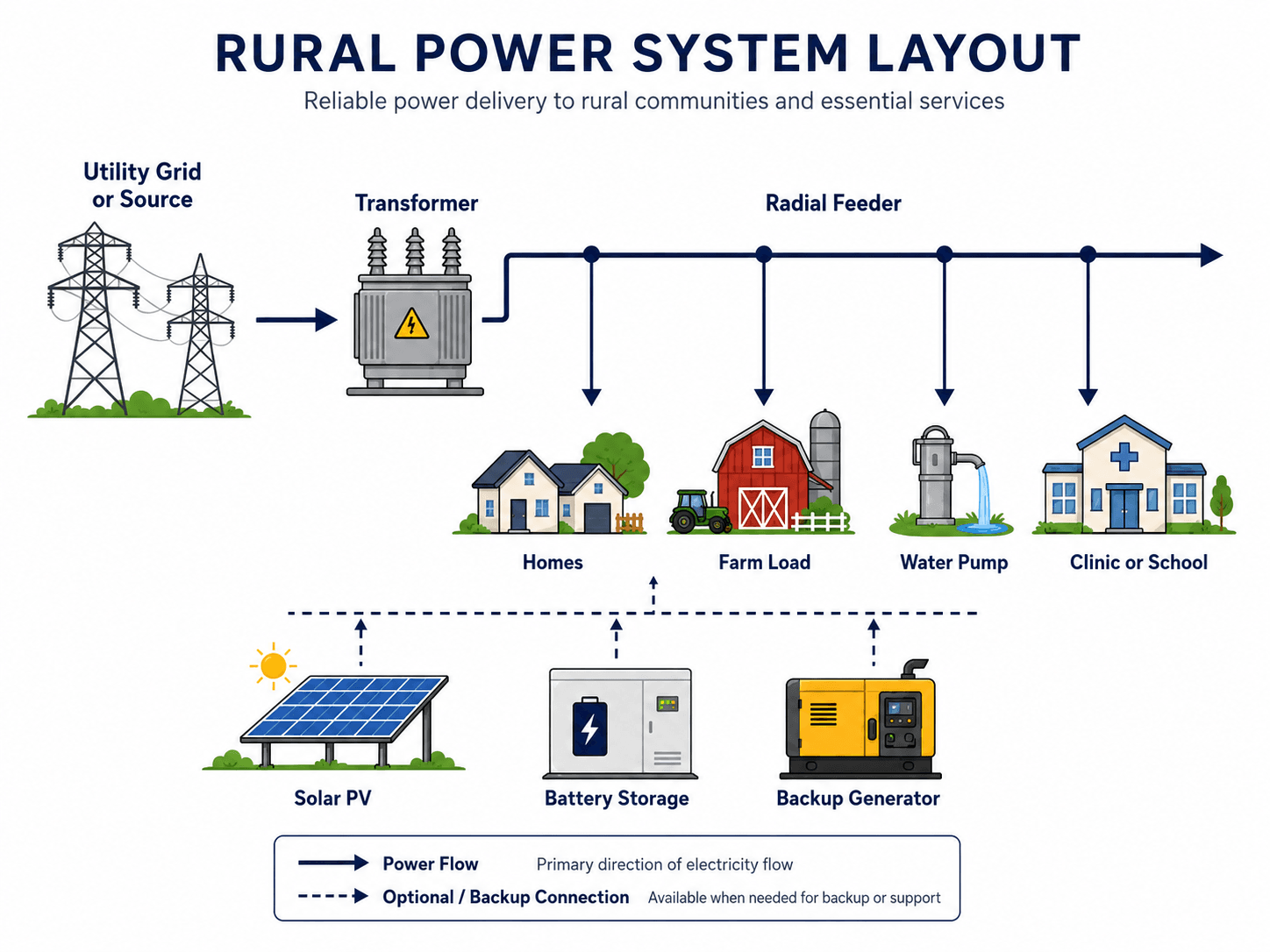
The important detail is not just the equipment list. The long radial feeder, scattered load points, and optional backup resources are what make rural power design different from dense urban distribution.
What Is a Rural Power System?
A rural power system is an electrical supply and distribution arrangement built for areas where customers, farms, facilities, or community loads are spread over long distances. It may be connected to a utility grid, supplied by a local microgrid, operated as a stand-alone system, or supported by a hybrid mix of solar, wind, battery storage, diesel generation, or other local energy resources.
In power systems engineering, the rural context changes the design problem. A feeder serving a few distant loads may have more voltage-drop and outage exposure than a shorter urban feeder serving many customers. A remote clinic, water pump, or farm load may also require higher reliability than the surrounding load density would suggest.
The best rural power system is therefore not always the most advanced system. It is the system that can deliver acceptable voltage, capacity, protection, reliability, maintainability, and cost over the full life of the project.
How Rural Power Systems Differ From Urban Power Systems
Rural power systems are not simply smaller urban systems. The same electrical principles apply, but the design priorities shift because the loads are farther apart, the feeder exposure is greater, and service restoration is often more difficult.
| Design issue | Rural power systems | Urban power systems |
|---|---|---|
| Load density | Low and scattered, with homes, farms, pumps, telecom sites, and small community facilities spread over long distances. | Higher and more compact, with many customers served from shorter feeder routes. |
| Feeder layout | Long radial feeders and laterals are common, so one fault can affect a large geographic area. | More interconnected feeders, switching options, and alternate supply paths may be available. |
| Voltage control | Voltage drop and voltage regulation are often major constraints at remote load points. | Shorter conductor runs and higher load density usually make voltage control easier to manage. |
| Outage exposure | Storms, vegetation, animals, lightning, long spans, and difficult road access can drive reliability performance. | Crews, spare parts, switching access, and restoration options are often closer to the affected equipment. |
| Cost driver | Distance, cost per customer, maintenance logistics, and reliability for critical loads often dominate. | Capacity, congestion, land use, undergrounding, and peak demand are more likely to dominate. |
| Planning focus | The design must balance grid extension, microgrids, stand-alone power, backup generation, and maintainability. | The design is more often focused on load growth, network reinforcement, switching, and urban reliability standards. |
A rural feeder may serve less total load than an urban feeder but still be harder to design well because the loads are distant, the outage exposure is larger, and the economics depend heavily on distance and maintenance access.
Main Types of Rural Power Systems
Rural electrification can be solved in several ways. The right architecture depends on how far the load is from the existing grid, whether loads are clustered or scattered, how critical the loads are, and who will operate and maintain the system.
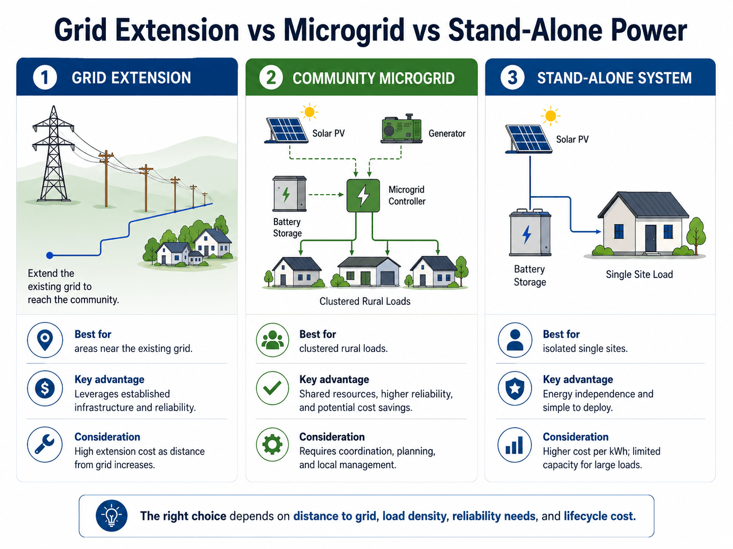
| Rural system type | Best fit | Engineering concern |
|---|---|---|
| Grid extension | Rural communities or farms located close enough to existing utility infrastructure that line extension is practical. | Long conductors, voltage drop, pole-line exposure, right-of-way, and extension cost can dominate the design. |
| Rural radial distribution | Utility-supplied rural areas with scattered loads served from a feeder, laterals, and distribution transformers. | Fault isolation, voltage regulation, vegetation exposure, and outage response are often more important than load density alone. |
| Community microgrid | Clustered rural loads such as a village, campus, islanded community, agricultural cooperative, or remote critical facility group. | Controls, protection, ownership, dispatch logic, operator training, and maintenance planning must be credible. |
| Stand-alone power system | Single isolated loads such as telecom sites, water pumps, remote cabins, monitoring stations, or small off-grid facilities. | Battery autonomy, backup strategy, load growth, seasonal resource variation, and service access control reliability. |
| Hybrid rural power system | Areas where solar, wind, batteries, diesel, or other sources are combined to reduce fuel use and improve resilience. | Resource variability, generator run hours, battery cycling, controls, fuel logistics, and lifecycle replacement cost. |
Key Components in a Rural Power System
Rural systems use many of the same components found in other distribution networks, but the placement, ratings, and maintenance strategy are different. A transformer on a long rural feeder, for example, is not just a voltage-conversion device; it is also a field asset that must survive weather, lightning exposure, animal contact, load growth, and slow restoration access.
| Component | What it does | Rural engineering check |
|---|---|---|
| Utility source or local generation | Provides the electrical energy entering the rural system. | Confirm capacity, availability, fuel or resource supply, outage exposure, and whether local generation can support critical loads. |
| Distribution feeder | Carries power over distance from the source to rural load areas. | Review conductor size, route length, thermal loading, voltage drop, lightning exposure, and right-of-way maintenance. |
| Transformers | Step voltage up or down for distribution and end-use service. | Check kVA rating, voltage class, impedance, protection, grounding, loading diversity, and future expansion margin. |
| Protective devices | Detect and isolate faults using fuses, reclosers, breakers, sectionalizers, and relays. | Coordinate protection for long feeder lengths, low fault current, lateral fuses, inverter-based sources, and restoration logic. |
| Battery energy storage | Stores energy for backup, peak support, renewable smoothing, or islanded operation. | Evaluate autonomy hours, cycling, temperature limits, replacement cost, state-of-charge controls, and backup priority loads. |
| Solar PV, wind, or other local resources | Reduce fuel use or support local supply where resources are available. | Compare seasonal production with the actual load profile, not just annual energy totals. |
| Controls and communications | Coordinate generation, storage, switching, metering, alarms, and microgrid operation. | Confirm the control system still works when communications are weak, field crews are unavailable, or a device fails locally. |
Rural Power System Design Workflow
A rural power design should start with the load and service objective, not with a preferred technology. Solar panels, batteries, transformers, poles, and generators only make sense after the engineer understands the demand profile, critical loads, allowable outages, expansion plan, and practical maintenance model.
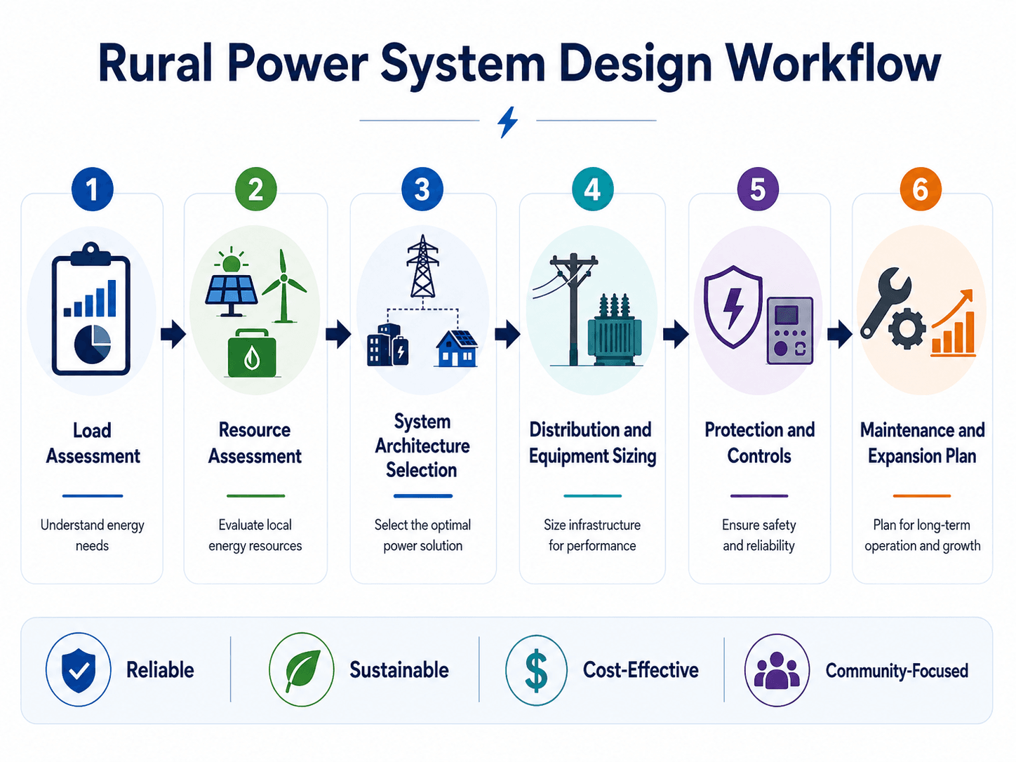
Text version of the workflow
- Load assessment: define peak demand, daily energy, seasonal loads, motor starts, and critical loads.
- Resource assessment: compare grid access, solar, wind, diesel, hydro, batteries, fuel delivery, and local operating capability.
- Architecture selection: screen grid extension, rural feeder service, microgrid, stand-alone power, or hybrid supply.
- Distribution and equipment sizing: check conductors, transformers, voltage regulation, thermal loading, and future expansion.
- Protection and controls: coordinate fuses, reclosers, relays, inverter behavior, islanding, and switching procedures.
- Maintenance and expansion planning: define spare parts, inspection access, local training, monitoring, and long-term load growth.
Start with the load profile
Rural loads are rarely uniform. A farm may have irrigation pumps, grain dryers, refrigeration, welders, and seasonal equipment. A clinic or school may have smaller peak demand but higher continuity requirements. A water system may have motor-starting current that controls conductor size or generator sizing even if daily energy use is modest.
Separate critical loads from convenience loads
A rural system should identify which loads must stay energized during an outage. Clinics, water pumps, communications equipment, refrigeration, emergency lighting, and control systems may need backup priority, while nonessential loads can be shed. This separation can reduce battery size, generator fuel use, and restoration complexity.
Select the architecture before sizing equipment
Engineers should compare grid extension, local distribution, microgrid, and stand-alone options before final equipment sizing. A conductor that looks oversized for normal load may be justified by voltage drop, motor starting, or future expansion. A battery sized only for average daily energy may fail if weather reduces renewable output during a critical period.
Design for operation, not only installation
Rural systems are often far from spare parts, utility crews, specialist technicians, and communication networks. That means equipment standardization, simple switching procedures, clear labeling, local training, remote monitoring, and realistic maintenance intervals can matter as much as initial electrical performance.
What Controls Rural Power System Design?
Rural power design is controlled by a combination of electrical, geographic, economic, and operational constraints. The electrical design has to work during normal load, peak load, fault conditions, outage restoration, and future growth.
| Design control | Why it matters | Engineering implication |
|---|---|---|
| Distance from the grid | Long line extensions add conductor cost, pole-line exposure, losses, easements, and maintenance burden. | Beyond a practical distance, a microgrid or stand-alone system may become more attractive than extending the feeder. |
| Load density | A sparse load spread over many miles creates a high infrastructure cost per customer or per kilowatt served. | Clustered rural loads are better candidates for shared microgrid or mini-grid infrastructure than isolated single loads. |
| Voltage regulation | Long rural conductors can create unacceptable voltage at remote loads, especially during motor starting or peak demand. | Engineers may need larger conductors, voltage regulators, capacitors, local generation, or load management. |
| Reliability target | A remote home, irrigation pump, water station, clinic, and telecom site do not all have the same outage tolerance. | Critical loads may justify batteries, backup generators, transfer logic, sectionalizing, or higher maintenance priority. |
| Protection coordination | Fault current may be lower at remote feeder ends, and inverter-based sources may not behave like synchronous machines. | Protective devices must clear real faults without nuisance trips or leaving unsafe energized sections in service. |
| Maintenance access | Remote equipment may be difficult to reach during storms, flooding, snow, poor road conditions, or agricultural operations. | Asset placement, spare parts, manual bypass options, labeling, and operator training should be reviewed early. |
Lifecycle cost drivers
First cost can be misleading in rural power design. A line extension may have a high initial cost but lower operating complexity, while a stand-alone or hybrid system may avoid long poles and conductors but require batteries, controls, fuel logistics, and periodic replacements.
| Cost driver | Why it matters in rural systems | Design implication |
|---|---|---|
| Distance to existing grid | Drives poles, conductors, right-of-way, losses, and long-term maintenance exposure. | Long distance can shift the preferred solution toward microgrid or stand-alone power. |
| Load density | Determines how much infrastructure cost is shared across homes, farms, facilities, or businesses. | Clustered loads can justify shared infrastructure better than isolated loads. |
| Reliability target | Backup generation, storage, switching, monitoring, and redundancy add cost. | Critical-load separation can reduce the amount of backup capacity needed. |
| Fuel logistics | Diesel delivery, storage, road access, and generator run hours affect operating cost and resilience. | Hybrid renewable-storage systems can reduce fuel use but still need dispatchable backup planning. |
| Battery replacement | Battery life, cycling, temperature, and replacement schedule can dominate lifecycle cost. | Battery sizing should be based on duty cycle and critical load strategy, not just nameplate capacity. |
| Maintenance access | Remote service trips increase outage duration and operating cost. | Standardized equipment, accessible switching, and local training can reduce lifecycle risk. |
If the design only compares capital cost, it is incomplete. Rural power decisions should also compare voltage performance, restoration time, fuel delivery, battery replacement, vegetation exposure, communications reliability, operator skill, and realistic load growth.
Voltage Drop, Protection, and Weak Feeder Behavior
Long rural feeders are sensitive to impedance. Current flowing through conductor resistance and reactance causes voltage drop, and the effect becomes more noticeable at distant loads. This is why voltage regulation is often a central rural distribution concern.
In practical terms, voltage drop increases as load current \(I\) increases or as feeder impedance \(Z_{\text{feeder}}\) increases. Feeder impedance depends on conductor length, conductor size, material, configuration, and operating frequency. Detailed design uses the appropriate single-phase or three-phase voltage-drop method, but the engineering lesson is simple: long rural paths make voltage harder to control.
- \(I\) Load current. Motor starts, irrigation pumps, and seasonal agricultural loads can create short-duration voltage problems even when average energy use is modest.
- \(Z_{\text{feeder}}\) Feeder impedance. Longer conductors, smaller wire sizes, and certain configurations increase the voltage drop between source and load.
- \(\Delta V\) Voltage drop between the source and the load. Excessive drop can cause poor motor performance, equipment trips, flicker, or customer complaints.
Protection is harder when fault current is low
Rural feeders may have lower available fault current at remote ends than near the substation or source. That can make fuse, recloser, and relay coordination more difficult. The protection must still distinguish temporary faults, permanent faults, overloads, inrush, and abnormal inverter behavior. For deeper protection context, see protective relays.
Distributed resources can change power flow
Solar PV, batteries, and local generation may reduce losses and support remote voltage, but they can also create reverse power flow, islanding questions, and protection coordination changes. On rural feeders, distributed resources should be treated as part of the power system, not as simple add-ons.
Example Rural Power System Decision
Consider a rural service area with 12 homes, one community water pump, one small clinic, seasonal irrigation demand, and poor road access during storms. The nearest existing feeder is about 4 miles away. Solar resource is available, but generator fuel delivery is possible only by road.
Screen the options
| Option | Why it may work | Why it may not work | Engineering judgment |
|---|---|---|---|
| Grid extension | Uses established utility infrastructure and may simplify long-term ownership. | Four miles of line may be costly, exposed to storms, and difficult to maintain. | Worth screening if load growth is likely and the utility can support voltage and protection requirements. |
| Community microgrid | Homes, clinic, and water pump can share solar, battery, and generator resources. | Requires controls, ownership structure, local maintenance, protection coordination, and dispatch planning. | Strong candidate if loads are clustered and the clinic/water pump need higher reliability. |
| Stand-alone systems | Works well for isolated single loads such as the water pump or a remote telecom point. | May duplicate batteries, controls, and maintenance across multiple sites. | Best when loads are far apart or when only one critical load needs independent service. |
| Hybrid solar-battery-diesel | Reduces fuel use while keeping dispatchable backup for low-sun periods or critical outages. | Requires careful battery sizing, generator maintenance, fuel planning, and load-shedding logic. | Often practical when renewable energy can support normal operation but reliability still needs firm backup. |
Interpretation
In this scenario, the best answer is probably not one technology. A grid extension may be justified if future growth is strong. A community microgrid may be stronger if the loads are clustered and reliability is important. Stand-alone power may still be useful for an isolated pump or communications load. The engineering decision should compare lifecycle cost, voltage performance, critical-load support, and maintainability.
Senior Engineer Review Checklist for Rural Power Systems
A rural power system review should trace the system from energy source to end-use load, then back through protection, controls, and maintenance. The checklist below is designed to catch practical issues that a simple equipment list or single-line diagram may hide.
Define the service objective, map the load profile, compare grid extension and local supply options, check voltage and thermal performance, review fault isolation, verify backup operation for critical loads, and confirm the system can be maintained with available crews, spares, and access.
| Review check | What to look for | Why it matters |
|---|---|---|
| Load profile is realistic | Peak kW, daily kWh, motor starts, seasonal agricultural loads, critical loads, and future growth are separated. | Average energy alone can understate generator size, conductor size, battery autonomy, and voltage-drop risk. |
| Architecture choice is justified | Grid extension, microgrid, stand-alone, and hybrid options are compared against distance, load density, and reliability needs. | A technology-first decision can overbuild one part of the system while ignoring lifecycle cost or maintainability. |
| Priority loads are separated | Critical services such as clinics, water pumping, refrigeration, communications, and controls are identified separately from nonessential loads. | Backup systems become more practical when they preserve essential service instead of trying to support every load equally. |
| Voltage profile is checked at remote loads | Far-end loads, motor-starting cases, peak load periods, and distributed generation operating states are reviewed. | Rural customers may experience poor voltage even when the source equipment is correctly rated. |
| Protection coordination matches the field | Fuses, reclosers, breakers, relays, inverter behavior, and fault current at remote points are coordinated. | Protection that looks acceptable near the source may fail to clear faults properly at the end of a long feeder. |
| Backup power supports priority loads | Critical loads are identified and separated from nonessential loads where practical. | Batteries and generators can be wasted if they support every load equally instead of preserving essential service. |
| Maintenance plan is credible | Spare parts, access roads, inspection frequency, local training, labeling, communications, and emergency procedures are documented. | Remote systems fail faster when maintenance depends on unavailable specialists or unclear switching procedures. |
Engineering Judgment and Field Reality
Rural power systems are exposed systems. Poles, conductors, transformers, fuses, reclosers, and communication links may be spread across fields, forests, mountains, flood-prone roads, or agricultural operations. Weather, vegetation, lightning, animals, dust, corrosion, and road access can control reliability as much as the electrical ratings do.
Load behavior is also different from a dense urban feeder. A single pump, compressor, irrigation motor, grain dryer, or workshop load can create a noticeable voltage event. A small clinic or water station may not be a large load, but it may be a critical load. The engineering decision is therefore not only “How much power is needed?” but “Which loads must stay energized, and under what field conditions?”
Ownership and operator skill also matter. A utility-owned rural feeder, a cooperative microgrid, and a privately maintained stand-alone system may use similar equipment but require very different maintenance responsibilities, documentation, spare parts, switching procedures, and training.
Rural reliability is often improved by simple, practical decisions: clear sectionalizing, accessible switches, standardized transformer sizes, lightning protection where appropriate, vegetation management, realistic spare parts, and local operators who understand the system.
When This Breaks Down
Simplified rural power diagrams are useful for learning, but they can become misleading when they hide operating constraints. A clean drawing may show solar PV, a battery, a generator, and a feeder working together, but the real system still needs control logic, protection coordination, fault isolation, grounding, communications, and maintenance procedures.
- Average load is used instead of peak and motor-starting load: the system may appear adequately sized but still experience voltage sag, generator overload, or nuisance trips.
- Renewable production is treated as firm capacity: solar and wind reduce energy cost, but storage or dispatchable backup is needed when resource availability does not match load demand.
- Protection settings are copied from a stronger grid: long feeders, low fault current, and inverter-based sources can make standard assumptions fail.
- Maintenance is assumed rather than designed: remote equipment can remain out of service for extended periods if spare parts, road access, and operator responsibilities are not planned.
- Future load growth is ignored: new homes, irrigation, refrigeration, EV charging, telecom equipment, or agricultural processing can quickly change the design basis.
Common Mistakes and Practical Checks
The most common rural power mistakes come from oversimplifying the system as either “just a long distribution line” or “just an off-grid solar system.” In practice, rural systems are a mix of power delivery, reliability, controls, protection, maintenance, and economics.
- Ignoring end-of-line voltage: always check voltage at the farthest and most sensitive loads, not only at the transformer or source.
- Undervaluing switching and sectionalizing: a rural feeder without practical isolation points can turn one small fault into a large outage area.
- Oversizing generation while undersizing distribution: more generation does not fix conductor limitations, poor voltage regulation, or inadequate protection.
- Forgetting fuel and battery logistics: diesel availability, battery replacement, temperature exposure, and maintenance intervals should be part of lifecycle planning.
- Treating communications as guaranteed: microgrid and monitoring systems should have a safe fallback mode when communications are weak or unavailable.
Do not choose between grid extension, microgrid, and stand-alone power using only first cost. For rural systems, lifecycle cost, outage impact, voltage performance, maintenance access, and future growth can reverse the apparent answer.
Useful References and Design Context
Rural electrification projects often involve technical design, service planning, ownership, maintenance, and local operating capability. Engineers use public guidance and standards families to frame requirements, but final designs still depend on project-specific criteria, utility requirements, equipment ratings, interconnection rules, electrical codes, and local conditions.
- International Electrotechnical Commission: IEC rural electrification guidance for universal electricity access is useful for understanding rural electrification context, autonomous systems, and decentralized energy access. It supports planning context, while final project design should still follow applicable utility requirements, electrical codes, equipment standards, interconnection rules, and site-specific criteria.
- Project-specific criteria: Utility interconnection rules, owner reliability targets, local electrical codes, terrain, environmental exposure, and available maintenance resources can control the final design.
- Engineering use: References help frame the design process, but engineers still need site load data, field conditions, equipment ratings, protection studies, and a maintainable operating plan.
Frequently Asked Questions
A rural power system is an electrical supply system designed for remote, low-density, agricultural, or sparsely populated areas. It may use long radial distribution feeders, grid extensions, stand-alone generation, batteries, diesel backup, renewable energy, or a local microgrid depending on load density, reliability needs, distance from the grid, and maintenance access.
Rural power systems usually serve fewer customers over longer distances, so voltage drop, line exposure, storm damage, vegetation, protection coordination, and maintenance response time become more important. Urban systems often have higher load density, shorter feeders, more switching flexibility, and more redundancy.
A rural microgrid becomes attractive when the community is far from the existing grid, the cost of extending lines is high, loads are clustered enough to share infrastructure, and local generation or storage can improve reliability. It is not automatically better; operations, protection, maintenance, ownership, and lifecycle cost must also be reviewed.
Voltage drop is common because rural feeders are often long and radial, while loads may include motors, pumps, irrigation equipment, grain handling equipment, or other demand that changes quickly. The farther current travels through conductors, the more conductor impedance affects delivered voltage at the end of the feeder.
Summary and Next Steps
Rural power systems are electrical systems designed around distance, low load density, reliability needs, and field maintainability. They may use utility grid extension, radial distribution, microgrids, stand-alone systems, or hybrid combinations of renewable generation, storage, and backup power.
The key engineering task is to match the architecture to the load profile and field reality. Voltage regulation, protection coordination, critical-load planning, maintenance access, backup priorities, and lifecycle cost often matter more than the name of the technology selected.
Where to go next
Continue your learning path with related Turn2Engineering resources.
-
Distribution Lines
Learn how feeders, conductors, poles, transformers, and protective devices deliver power from source points to end-use loads.
-
Stand-Alone Power Systems
Review how independent power systems support isolated loads without a continuous connection to the utility grid.
-
Smart Grids
Explore how monitoring, communications, automation, and distributed resource coordination can improve modern power systems.