Key Takeaways
- Core idea: Refrigeration cycles move heat from a cold region to a warmer region by adding work input or another energy source.
- Engineering use: The vapor-compression cycle is the main model behind refrigerators, air conditioners, heat pumps, chillers, and many industrial cooling systems.
- What controls it: Performance depends mainly on evaporating temperature, condensing temperature, refrigerant properties, compressor efficiency, pressure drops, superheat, and subcooling.
- Practical check: A real refrigeration cycle always performs worse than the ideal diagram because of irreversibility, heat-transfer limits, throttling losses, and pressure drops.
Table of Contents
Introduction
Refrigeration cycles are thermodynamic processes that move heat from a cold space to a warmer environment by adding work or another energy input. The most common cycle is the vapor-compression refrigeration cycle, which uses an evaporator, compressor, condenser, and expansion valve to absorb heat at low pressure and reject heat at high pressure.
Vapor-Compression Refrigeration Cycle Diagram

First notice the color change: the red side represents the higher-pressure, higher-temperature portion of the cycle, while the blue side represents the lower-pressure, lower-temperature portion where useful cooling occurs.
What is a Refrigeration Cycle?
A refrigeration cycle is a controlled thermodynamic loop that removes heat from a space, product, fluid, or process and rejects that heat somewhere else. The cycle does not destroy heat. It moves heat “uphill” from a colder region to a warmer region by adding energy to the system.
The most common engineering model is the vapor-compression cycle. It is used in home refrigerators, air conditioners, heat pumps, commercial refrigeration racks, data center cooling systems, and industrial chillers. The cycle is closely tied to broader thermodynamic cycles, but its purpose is the reverse of a heat engine: instead of producing work from heat flow, it uses work to move heat in the desired direction.
The key engineering idea is temperature lift. A system that only has to move heat across a small temperature difference can usually operate with a higher coefficient of performance. A system that must maintain a very cold evaporator while rejecting heat to a hot outdoor environment requires more compressor work and usually has a lower COP.
How the Vapor-Compression Refrigeration Cycle Works
The vapor-compression cycle works by forcing a refrigerant to change pressure, temperature, and phase as it travels through four components. The refrigerant absorbs heat at low pressure in the evaporator, becomes a vapor, is compressed to a high-pressure vapor, rejects heat in the condenser, and is throttled back to low pressure through the expansion valve.
| Step | Component | What happens | Energy interaction |
|---|---|---|---|
| 4 → 1 | Evaporator | Low-pressure refrigerant absorbs heat and boils into vapor. | \(Q_L\) enters the refrigerant. |
| 1 → 2 | Compressor | Vapor pressure and temperature increase. | \(W_{in}\) is added by the compressor. |
| 2 → 3 | Condenser | High-pressure refrigerant rejects heat and condenses. | \(Q_H\) leaves the refrigerant. |
| 3 → 4 | Expansion valve | Pressure drops through throttling. | \(h_3 \approx h_4\) in the ideal model. |
Step 1: Evaporator Absorbs Heat
In the evaporator, low-pressure refrigerant absorbs heat from the refrigerated space, air stream, water loop, or process fluid. This is the useful cooling effect. The refrigerant boils and usually leaves as vapor at state 1.
Step 2: Compressor Raises Pressure and Temperature
The compressor raises the refrigerant from low pressure to high pressure. This step requires work input and is usually the largest energy cost in the cycle. In an ideal analysis, compression is often treated as isentropic. In a real compressor, losses increase discharge temperature and required power.
Step 3: Condenser Rejects Heat
In the condenser, high-pressure refrigerant rejects heat to outdoor air, cooling water, or another heat sink. As heat leaves the refrigerant, the vapor condenses into liquid. The condenser rejects both the heat absorbed in the evaporator and the work added by the compressor.
Step 4: Expansion Valve Drops Pressure
The expansion valve reduces pressure without producing useful work. The refrigerant leaves as a cold low-pressure mixture that can absorb heat in the evaporator. This throttling process is simple and reliable, but it creates irreversibility and is one reason the real cycle is not a perfect reversed Carnot cycle.
Refrigerator, Air Conditioner, Chiller, and Heat Pump: Same Cycle, Different Output
A refrigerator, air conditioner, chiller, and heat pump can all use the same basic vapor-compression loop. The difference is which heat transfer is considered useful. Cooling systems care about heat absorbed in the evaporator. Heating-mode heat pumps care about heat rejected at the condenser.
| System | Useful output | Main heat exchanger of interest | Common COP form |
|---|---|---|---|
| Refrigerator | Cooling inside the cabinet or cold room | Evaporator | \(COP_R = Q_L / W_{in}\) |
| Air conditioner | Cooling and dehumidifying indoor air | Evaporator | \(COP_R = Q_L / W_{in}\) |
| Chiller | Cooling water, glycol, brine, or process fluid | Evaporator | \(COP_R = Q_L / W_{in}\) |
| Heat pump | Heating the occupied space or process stream | Condenser | \(COP_{HP} = Q_H / W_{in}\) |
Always define the useful output before comparing COP values. A cooling COP and a heating COP can describe the same physical machine but use different heat-transfer terms in the numerator.
Pressure-Enthalpy Diagram for Refrigeration Cycles
A pressure-enthalpy diagram, often called a P-h diagram, is one of the clearest ways to analyze a refrigeration cycle. It connects the physical equipment to measurable refrigerant properties such as pressure, enthalpy, phase, and energy transfer.
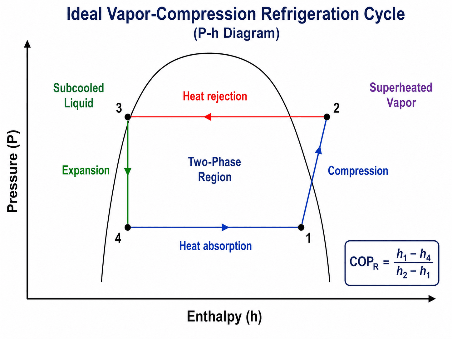
On the diagram, the bottom process represents heat absorption in the evaporator, the right-side process represents compression, the top process represents heat rejection in the condenser, and the left-side process represents expansion. The saturation dome separates the subcooled liquid, two-phase, and superheated vapor regions.
How to Read the P-h Diagram
- Locate the low-pressure evaporator line.
- Find state 1 near the compressor inlet, usually as vapor leaving the evaporator.
- Follow compression from state 1 to state 2.
- Move across heat rejection from state 2 to state 3.
- Drop through throttling from state 3 to state 4.
- Move across evaporation from state 4 back to state 1.
- Read \(h_1\), \(h_2\), \(h_3\), and \(h_4\) from the chart or refrigerant property data.
- Calculate cooling effect, compressor work, heat rejection, and COP.
| State | Location | Typical condition | Why it matters |
|---|---|---|---|
| 1 | Compressor inlet / evaporator outlet | Low-pressure vapor, often slightly superheated | Protects the compressor from liquid refrigerant and defines \(h_1\). |
| 2 | Compressor outlet / condenser inlet | High-pressure superheated vapor | Determines discharge temperature, \(h_2\), and compressor work. |
| 3 | Condenser outlet | High-pressure liquid, often subcooled | Feeds the expansion device and defines the start of throttling. |
| 4 | Expansion valve outlet / evaporator inlet | Low-pressure liquid-vapor mixture | Enters the evaporator ready to absorb heat. |
- \(COP_R\) Refrigeration coefficient of performance, a ratio of useful cooling to compressor work.
- \(Q_L\) Cooling effect absorbed in the evaporator, often in kJ/kg or Btu/lbm on a refrigerant mass basis.
- \(Q_H\) Heat rejected at the condenser. It includes evaporator heat plus compressor work.
- \(W_{in}\) Compressor work input, usually estimated from the enthalpy rise across the compressor.
- \(h_1,h_2,h_3,h_4\) Refrigerant enthalpies at the main state points of the cycle.
Cooling Capacity, Refrigeration Effect, and Tons of Refrigeration
Refrigeration effect and cooling capacity are related but not identical. Refrigeration effect is often expressed per unit mass of refrigerant, such as kJ/kg or Btu/lbm. Cooling capacity is a rate of heat removal, such as kW, Btu/hr, or tons of refrigeration.
In HVAC practice, one ton of refrigeration is equal to 12,000 Btu/hr, which is approximately 3.517 kW. This unit is common for air conditioners, chillers, and refrigeration equipment, while thermodynamics problems often use kJ/kg and refrigerant mass flow rate.
A compressor-only COP excludes fans, pumps, controls, crankcase heaters, and defrost energy. A whole-system COP includes more parasitic loads and is usually lower.
Where Refrigeration Cycles Are Used in Engineering
Refrigeration cycles appear anywhere engineers need controlled cooling, dehumidification, food preservation, process temperature control, or heat pumping. The same thermodynamic loop can be used to cool a space, chill a fluid, freeze a product, or heat a building when the desired output is heat rejection instead of cooling.
- HVAC systems: air conditioners and heat pumps use refrigeration cycles to move heat between indoor and outdoor environments.
- Commercial refrigeration: grocery cases, walk-in coolers, and freezers use cycle control to maintain product temperature.
- Industrial chillers: process plants use refrigeration cycles to cool water, glycol, brine, or process streams.
- Thermal design: refrigeration analysis connects directly to heat transfer, heat exchanger sizing, compressor selection, and energy efficiency.
Before analyzing COP, define the desired output. For a refrigerator or chiller, the useful output is heat absorbed at the evaporator. For a heat pump in heating mode, the useful output is heat rejected at the condenser.
What Controls Refrigeration Cycle Performance?
Refrigeration cycle performance is controlled by the temperature lift, the refrigerant states, and the real losses inside the components. The same equipment can perform very differently depending on outdoor temperature, evaporator temperature, airflow, fouling, refrigerant charge, and compressor efficiency.
| Factor | Why it matters | Engineering implication |
|---|---|---|
| Evaporating temperature | Lower evaporating temperature makes the compressor lift refrigerant from a lower pressure. | Very cold evaporators usually reduce COP and increase compressor work. |
| Condensing temperature | Higher condenser temperature raises high-side pressure. | Dirty condenser coils, hot ambient air, or poor heat rejection can sharply reduce performance. |
| Compressor efficiency | Real compression is not isentropic and creates additional heat and entropy. | Actual compressor power is higher than ideal compressor work. |
| Superheat | Some superheat protects the compressor from liquid refrigerant, but excessive superheat can reduce capacity. | Engineers balance compressor protection against evaporator effectiveness. |
| Subcooling | Subcooling helps ensure liquid refrigerant reaches the expansion valve. | Useful subcooling can improve stability, but abnormal values may indicate charge or heat rejection issues. |
| Pressure drop | Piping, coils, filters, and valves create losses between ideal state points. | Pressure drop shifts the actual cycle and usually lowers available refrigeration effect or increases compressor work. |
The easiest way to improve refrigeration COP is usually to reduce temperature lift: raise the evaporating temperature where possible, lower the condensing temperature where possible, and reduce unnecessary heat exchanger, airflow, and piping restrictions.
Why Refrigerant Choice Matters
Refrigerant selection affects the entire refrigeration cycle. The refrigerant controls the pressure-temperature relationship, latent heat, compressor discharge temperature, operating pressure range, oil compatibility, safety classification, environmental impact, and whether the equipment can operate reliably over the required temperature range.
| Refrigerant property | Why it matters | Practical implication |
|---|---|---|
| Pressure-temperature relationship | Sets evaporating and condensing pressures for the desired temperatures. | Affects compressor selection, piping pressure rating, and service conditions. |
| Latent heat | Controls how much heat can be absorbed during evaporation per unit mass. | Affects mass flow rate, equipment size, and capacity. |
| Discharge temperature | High discharge temperature can damage oil, valves, and compressor components. | May require staging, injection, cooling, or a different refrigerant. |
| Safety and environmental profile | Flammability, toxicity, global warming potential, and code requirements affect system design. | Can control refrigerant charge limits, ventilation, detection, and application suitability. |
Why Real Systems Do Not Use a Perfect Reversed Carnot Cycle
The reversed Carnot cycle is useful as an ideal benchmark because it represents the theoretical upper limit for refrigeration performance between two temperature reservoirs. Real vapor-compression systems use a more practical layout because a perfect reversed Carnot refrigeration cycle is difficult to build and control.
- Wet compression is undesirable: compressors are not designed to reliably compress a liquid-vapor mixture.
- Turbine expansion is often not economical: small HVAC&R systems usually use a throttling valve instead of an expansion turbine.
- Heat transfer needs finite temperature differences: real evaporators and condensers cannot transfer heat with zero temperature difference.
- Controls and reliability matter: vapor compression is a practical compromise between efficiency, cost, serviceability, and stable operation.
This is why a refrigeration cycle is often described as a reversed heat-engine cycle, while the real equipment is usually analyzed as an ideal or actual vapor-compression cycle rather than a perfect reversed Carnot cycle.
Ideal vs Actual Refrigeration Cycle
The ideal refrigeration cycle is useful for learning the process and estimating first-pass performance. Actual systems deviate from the ideal because heat exchangers are not perfect, compression is irreversible, and pressure losses occur throughout the system.
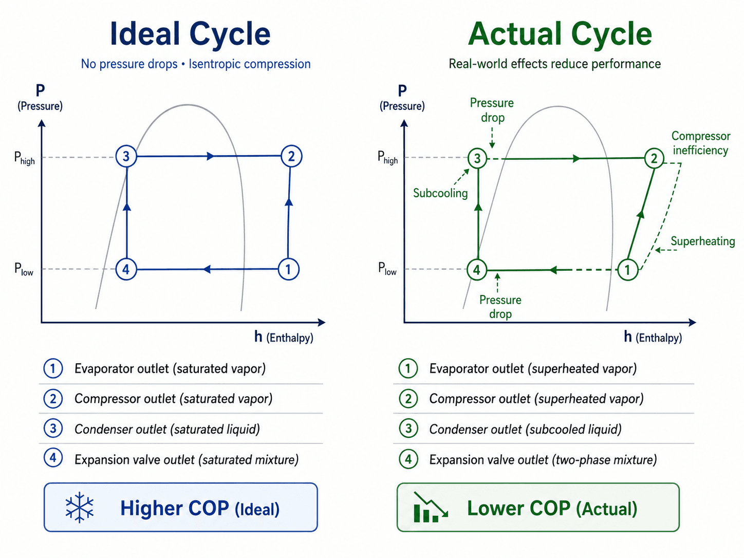
In practice, actual COP is lower than ideal COP. A clean textbook P-h diagram assumes no pressure losses and ideal compression. A real system must overcome frictional losses, heat exchanger approach temperatures, motor losses, imperfect expansion control, and changing operating conditions.
Common Types of Refrigeration Cycles
Vapor compression is the dominant refrigeration cycle, but it is not the only one. Engineers choose a cycle based on temperature range, available energy source, efficiency, refrigerant constraints, equipment complexity, and reliability requirements.
| Cycle type | Best fit | Main tradeoff |
|---|---|---|
| Vapor-compression cycle | Air conditioning, refrigerators, heat pumps, chillers, and commercial refrigeration. | High practical usefulness, but depends on compressor power and refrigerant selection. |
| Absorption refrigeration cycle | Applications where waste heat, gas heat, or solar thermal energy is available. | Can use heat input instead of mechanical compression, but equipment is larger and COP is usually lower. |
| Cascade refrigeration cycle | Very low-temperature systems where one refrigerant loop is not enough. | Handles large temperature lifts, but adds complexity and control requirements. |
| Multi-stage compression cycle | Industrial systems with large pressure ratios or intermediate cooling needs. | Can improve efficiency but adds compressors, controls, and maintenance needs. |
| Gas refrigeration cycle | Aircraft cooling and specialized systems using a reversed Brayton-style process. | Useful in certain gas-cycle applications, but not usually the best fit for common building cooling. |
| Transcritical CO₂ cycle | CO₂ systems where heat rejection can occur above the critical point. | Does not follow the same simple subcritical condensation path shown in beginner P-h diagrams. |
Refrigeration Cycle Design Review Checklist
A refrigeration cycle review should not stop at drawing the loop. Engineers check the operating temperatures, pressure levels, heat exchanger performance, compressor behavior, expansion device control, refrigerant choice, and whether the measured or calculated state points make physical sense.
Start with the cooling load and evaporator temperature, estimate condensing temperature, select or identify the refrigerant, locate state points on the P-h diagram, calculate refrigeration effect and compressor work, then compare ideal COP to expected real system performance.
| Check or decision | What to look for | Why it matters |
|---|---|---|
| Temperature lift | Compare evaporating temperature to condensing temperature. | A larger lift generally means more compressor work and lower COP. |
| Evaporator condition | Look for adequate heat absorption, airflow or fluid flow, and reasonable outlet superheat. | Poor evaporator performance reduces useful cooling and may cause unstable operation. |
| Condenser condition | Check whether heat rejection is limited by fouling, high ambient temperature, or low airflow. | High condensing pressure increases compressor power and operating temperature. |
| Expansion device behavior | Check whether refrigerant enters the evaporator as a low-pressure mixture rather than mostly vapor. | Improper expansion can reduce evaporator capacity and destabilize superheat control. |
| Compressor discharge state | Watch for excessive discharge temperature, abnormal pressure ratio, or signs of liquid slugging. | Compressor reliability often controls the real operating envelope of the system. |
| Oil return and serviceability | Check piping layout, velocity, traps, load range, and maintenance access. | A thermodynamically sound cycle can still fail if oil return and service access are poor. |
Worked Example: Estimating Refrigeration COP
A simple enthalpy-based example shows how the P-h diagram connects to useful cooling and compressor work. Assume a vapor-compression cycle has the following refrigerant enthalpies from a property table or P-h diagram:
- \(h_1 = 395 \, \text{kJ/kg}\) at the compressor inlet
- \(h_2 = 430 \, \text{kJ/kg}\) at the compressor outlet
- \(h_3 = 250 \, \text{kJ/kg}\) at the condenser outlet
- \(h_4 = 250 \, \text{kJ/kg}\) after the expansion valve
Engineering Meaning
A COP of 4.14 means the idealized cycle provides about 4.14 units of cooling for every 1 unit of compressor work input. The condenser rejects 180 kJ/kg because it must reject the 145 kJ/kg absorbed in the evaporator plus the 35 kJ/kg added by compressor work.
What Makes a Good Refrigeration Cycle Design?
A good refrigeration cycle design is not simply the one with the highest ideal COP. It must provide the required capacity, stay within safe pressure and temperature limits, operate reliably across load changes, and remain serviceable over the equipment life.
- Use the highest practical evaporating temperature that still meets the cooling requirement.
- Use the lowest practical condensing temperature through effective heat rejection.
- Maintain stable expansion control and appropriate evaporator superheat.
- Keep compressor discharge temperature within acceptable limits.
- Reduce pressure drop through coils, filters, piping, and valves.
- Select a refrigerant that fits the temperature range, safety requirements, equipment, and environmental constraints.
- Check oil return, service access, part-load control, and maintenance realities.
Engineering Judgment and Field Reality
Real refrigeration systems are controlled systems, not just thermodynamic diagrams. Expansion valves, compressor staging, variable-speed drives, fans, pumps, refrigerant charge, sensors, and control logic all affect the cycle. A mathematically acceptable state-point calculation can still represent a poor design if the system cannot operate reliably across part-load, startup, defrost, or high-ambient conditions.
The lowest possible evaporator temperature is not automatically the best design. Lower evaporator temperature can increase cooling potential at the coil, but it also increases compressor lift, reduces COP, raises frost risk, and may create comfort or product-control problems.
Experienced engineers also watch the difference between equipment rating conditions and actual operating conditions. A chiller, heat pump, or packaged refrigeration unit may perform well at a standard rating point but behave very differently when coils are dirty, ambient conditions are extreme, airflow is poor, or the load varies rapidly.
When This Breaks Down
The simple ideal refrigeration cycle becomes less reliable when the assumptions behind it no longer match the actual system. The diagram is still useful, but engineers need to adjust interpretation when real equipment behavior dominates the thermodynamic model.
- Large pressure drops: long piping runs, dirty coils, undersized valves, and restrictive filters can shift actual evaporating and condensing pressures.
- Non-ideal compression: compressors generate losses, heat, and discharge temperatures that are not captured by a perfectly isentropic line.
- Control instability: hunting expansion valves, poor sensor placement, or rapidly changing loads can make state points move instead of staying fixed.
- Refrigerant charge problems: undercharge and overcharge can both distort expected superheat, subcooling, capacity, and compressor reliability.
- Low-temperature freezer systems: very low evaporating temperatures may require multi-stage compression, economizers, or cascade systems.
- Cold-climate heat pumps: heating operation can include defrost cycles, supplemental heat, capacity drop, and control limits that are not shown on the simple loop.
- Transcritical CO₂ systems: some CO₂ systems reject heat above the critical point, so the familiar subcritical condensation section of the beginner diagram no longer applies in the same way.
- Variable-speed equipment: systems with modulating compressors, electronic expansion valves, and variable fans do not operate at one fixed cycle point.
Common Mistakes and Practical Checks
Most refrigeration-cycle mistakes come from confusing the physical equipment with the thermodynamic state points, or from applying the ideal diagram without considering real losses.
- Confusing heat absorbed with heat rejected: the evaporator cooling effect is not the same as the condenser heat rejection because condenser heat also includes compressor work.
- Assuming \(h_3\) and \(h_4\) are different in ideal throttling: the expansion valve is usually modeled as an isenthalpic device, so \(h_3 \approx h_4\).
- Using refrigerator COP for heat pump heating: refrigeration COP uses evaporator heat absorption as the useful output, while heat pump COP uses condenser heat rejection.
- Ignoring fan and pump power: a compressor-only COP can overstate full equipment efficiency when auxiliary power is significant.
- Forgetting part-load operation: systems often spend more time at part load than at peak design load, so controls and cycling behavior matter.
- Comparing COP values without conditions: COP is only meaningful when the evaporating temperature, condensing temperature, refrigerant, and system boundary are clear.
Do not judge refrigeration performance from a single COP number without knowing the evaporating temperature, condensing temperature, refrigerant, compressor assumptions, and whether auxiliary power is included.
Useful References and Design Context
Refrigeration-cycle theory is usually learned from thermodynamics, but real HVAC&R design also depends on equipment data, refrigerant properties, safety classifications, and recognized refrigeration practice.
- ASHRAE refrigeration learning resource: ASHRAE Fundamentals of Refrigeration covers refrigeration principles, thermodynamics, vapor-compression refrigeration, heat-pump cycles, refrigerants, and practical refrigeration system applications.
- Project-specific criteria: Final system selection depends on owner requirements, local codes, equipment listings, refrigerant rules, safety classification, installation conditions, and maintenance capability.
- Engineering use: Engineers combine thermodynamic cycle analysis with manufacturer performance data, heat exchanger design, compressor maps, control sequences, and field measurements before making final design decisions.
Frequently Asked Questions
A refrigeration cycle is a thermodynamic process that moves heat from a low-temperature space to a higher-temperature sink. The most common version is the vapor-compression cycle, which uses an evaporator, compressor, condenser, and expansion valve to create cooling.
The four main parts are the evaporator, compressor, condenser, and expansion valve. The evaporator absorbs heat from the cold space, the compressor raises refrigerant pressure, the condenser rejects heat, and the expansion valve reduces pressure before the refrigerant returns to the evaporator.
The pressure-enthalpy diagram shows how refrigerant pressure and enthalpy change through compression, condensation, expansion, and evaporation. Engineers use it to estimate cooling effect, compressor work, heat rejection, and coefficient of performance.
An actual refrigeration cycle is less efficient because real compressors are not isentropic, piping and heat exchangers have pressure drops, and the refrigerant often leaves the evaporator superheated and the condenser subcooled. These effects increase compressor work and reduce actual COP.
COP compares useful cooling or heating output to work input, while efficiency usually describes useful output as a fraction of energy input. Refrigeration COP can be greater than 1 because the system moves heat rather than converting work directly into cooling.
Summary and Next Steps
Refrigeration cycles explain how cooling systems move heat from a cold region to a warmer region. The vapor-compression cycle is the most important practical model because it connects the evaporator, compressor, condenser, and expansion valve into a repeatable thermodynamic loop.
The main engineering checks are the evaporating temperature, condensing temperature, refrigerant state points, compressor work, cooling effect, condenser heat rejection, COP, pressure drops, superheat, and subcooling. The ideal cycle is useful for learning and calculation, but real systems require judgment because losses, controls, refrigerants, and operating conditions change performance.
Where to go next
Continue your learning path with related Turn2Engineering resources.
-
Vapor Compression Cycle
Go deeper into the main cycle used by refrigerators, air conditioners, heat pumps, and chillers.
-
Thermodynamic Cycles
Review how refrigeration cycles compare with power cycles, heat engines, and other cyclic thermodynamic processes.
-
Heat Transfer
Understand the conduction, convection, and heat-exchanger behavior that controls evaporator and condenser performance.