Key Takeaways
- Core idea: A cyclic process brings a thermodynamic system back to its original state after a sequence of processes.
- Engineering use: Cyclic processes are the basis for heat engines, refrigerators, heat pumps, steam power cycles, and vapor-compression systems.
- What controls it: The process path controls heat transfer, work transfer, loop direction, and the enclosed area on a PV diagram.
- Practical check: \(\Delta U_{cycle}=0\) does not mean heat or work is zero; it means the system has no net internal energy change after one complete loop.
Table of Contents
Introduction
A cyclic process is a thermodynamic process where a system moves through multiple states and returns to its original state. Because the initial and final states are identical, the net change in internal energy over one complete cycle is zero, while heat and work can still be transferred during the cycle.
Pressure-Volume Diagram of a Cyclic Process
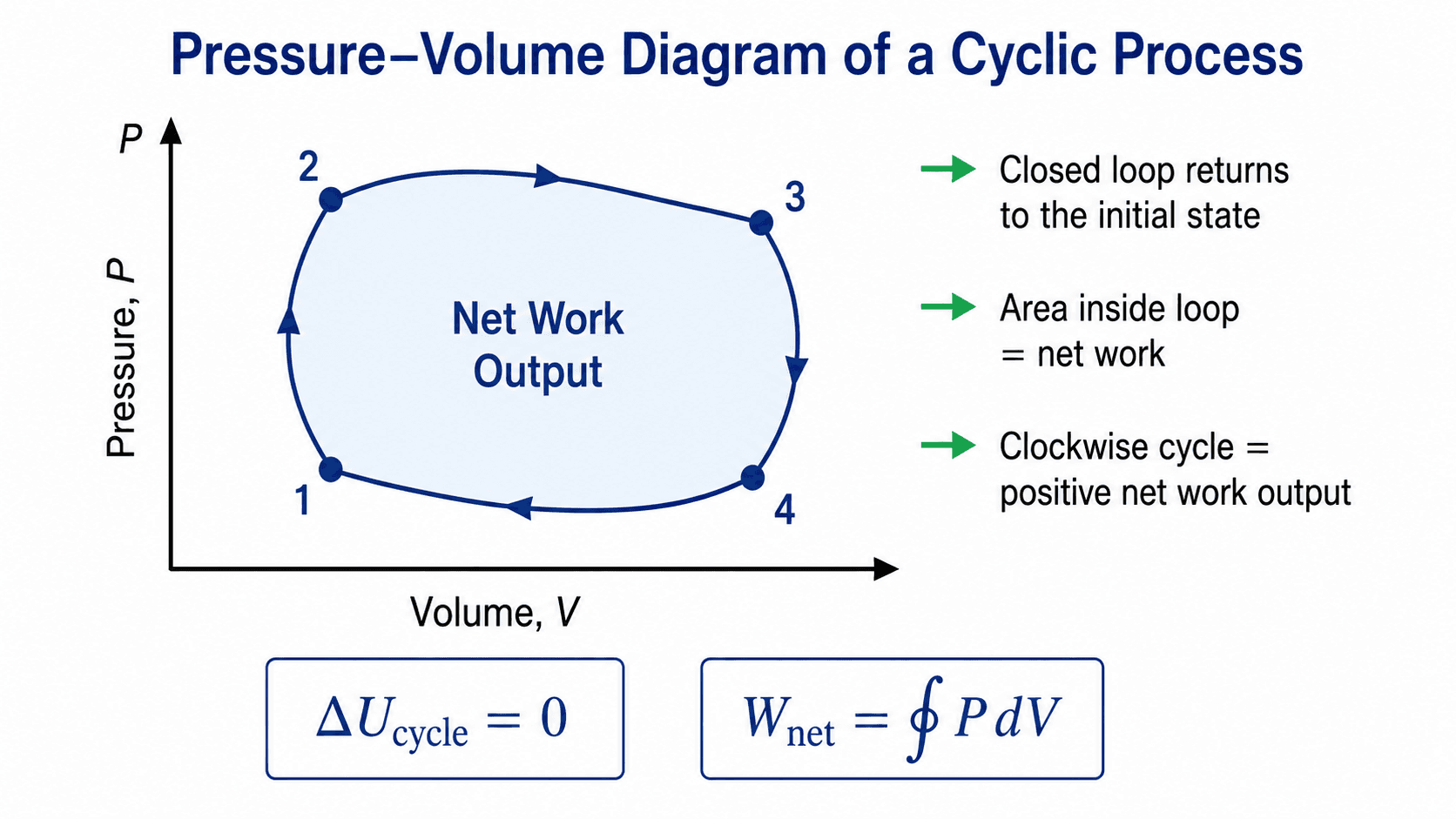
In this page, work done by the system is treated as positive. With that sign convention, a clockwise PV loop represents positive net work output and a counterclockwise PV loop represents net work input.
What Is a Cyclic Process?
A cyclic process is a sequence of thermodynamic processes that returns a system to the same state where it started. At the end of one complete cycle, state properties such as pressure, volume, temperature, internal energy, enthalpy, and entropy of the system return to their initial values.
The engineering value of a cyclic process is not simply that the system ends where it started. The value is that useful heat and work interactions can occur while the system completes the loop. That is why engines, refrigerators, heat pumps, turbines, compressors, and many power systems are studied as repeated thermodynamic cycles.
State properties reset after a complete cycle, but heat and work are path quantities. They occur during the path around the cycle and do not have to be zero.
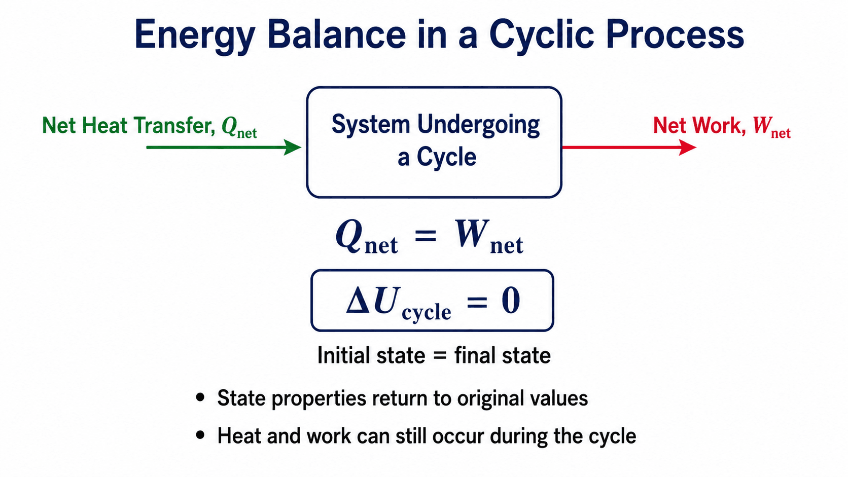
Cyclic Process Formula and Energy Balance
The two most important cyclic process formulas are \(\Delta U_{cycle}=0\) and \(Q_{net}=W_{net}\). The first comes from the system returning to its original state. The second comes from applying the first law of thermodynamics over the complete cycle.
For a complete cyclic process, the initial and final states are the same. Since internal energy is a state property, the net change in internal energy over the complete cycle is zero.
Substituting \(\Delta U_{cycle}=0\) into the first law gives the complete-cycle energy balance:
Why \(\Delta U_{cycle}=0\)
Internal energy depends on the state of the system, not the path used to reach that state. If the system starts and ends at the same thermodynamic state, its internal energy at the end of the cycle is the same as it was at the beginning.
Why \(Q\) and \(W\) Are Not Automatically Zero
Heat and work are not stored properties of the system. They are transfers that happen while the system moves through the path. A gas can absorb heat during one portion of the cycle, reject heat during another portion, perform work during expansion, and still return to the same state at the end.
State Properties vs Path Quantities
A strong understanding of cyclic processes depends on separating state properties from path quantities. State properties describe the condition of the system at a state. Path quantities describe energy transfers that occur while moving between states.
| Quantity | Type | Behavior over a complete cycle |
|---|---|---|
| Pressure, volume, temperature | State properties | Return to their initial values when the system returns to the same state. |
| Internal energy | State property | Has zero net change over a complete cycle: \(\Delta U_{cycle}=0\). |
| Enthalpy and entropy of the system | State properties | Return to initial values if the system returns to the same equilibrium state. |
| Heat transfer | Path quantity | Can be positive, negative, or zero depending on the path and reservoirs. |
| Work transfer | Path quantity | Can be positive, negative, or zero depending on the cycle direction and enclosed PV area. |
This distinction prevents the most common misunderstanding: \(\Delta U_{cycle}=0\) does not mean the cycle is energetically inactive. It means the system has no net internal energy storage change after one complete loop.
Entropy also needs careful interpretation. For an irreversible real cycle, the system may return to its starting entropy, but entropy is still generated in the surroundings and in the larger system-universe balance.
Work Done in a Cyclic Process on a PV Diagram
On a pressure-volume diagram, boundary work for a closed compressible system is related to the area under the process path. For a complete cyclic process, the net boundary work is the closed-loop integral around the cycle:
- \(P\) Pressure along the process path, commonly shown in kPa, Pa, psi, or bar.
- \(V\) System volume, commonly shown in m³, L, ft³, or in³ depending on the application.
- \(W_{net}\) Net boundary work over the complete cycle. In SI units, \(1\,kPa \cdot m^3 = 1\,kJ\).
Units and Sign Convention
Unit consistency matters in cyclic-process problems. In SI units, \(Pa \cdot m^3 = J\) and \(kPa \cdot m^3 = kJ\). In US customary units, work may be reported in ft-lbf, Btu, or another compatible energy unit depending on the pressure and volume units used.
The sign of work depends on the convention. This page uses the common thermodynamics convention where work done by the system is positive. Under that convention, a clockwise PV loop usually indicates positive net work output.
Before using a cyclic process diagram to calculate work, confirm whether the diagram represents a closed system, an open control volume, an idealized cycle, or measured equipment data. The same loop shape can imply different calculations depending on the system boundary.
Clockwise vs Counterclockwise Cyclic Processes
The direction of a PV loop helps identify whether the cycle behaves more like a work-producing device or a work-consuming device. It is one of the fastest ways to interpret a cyclic process diagram, but it should always be checked against the sign convention.
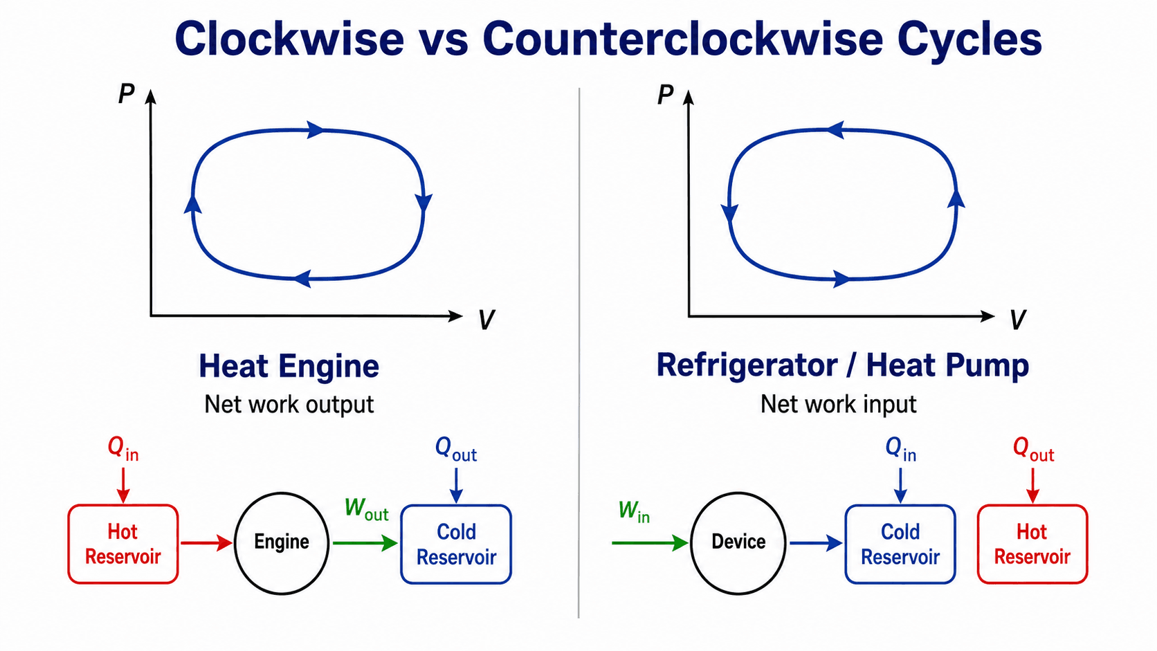
| PV loop direction | Typical device behavior | Energy meaning |
|---|---|---|
| Clockwise | Heat engine or power cycle | The system produces net work output over the complete cycle. |
| Counterclockwise | Refrigerator, heat pump, or reversed cycle | The system requires net work input to move heat or complete the cycle. |
| No enclosed area | Idealized limiting case | The net boundary work from the PV loop is zero or negligible. |
The loop direction is a powerful visual shortcut, but it should not replace a full energy balance. Engineers still check the heat inputs, heat rejections, work interactions, and sign convention before drawing final conclusions.
Examples of Cyclic Processes
Cyclic processes appear throughout mechanical and thermal engineering because many machines are designed to repeat the same energy-conversion pattern. The working fluid is the material that moves through the thermodynamic states of the cycle, such as air, steam, refrigerant, combustion gas, or a gas-vapor mixture.
| Cycle | Common application | Main idea |
|---|---|---|
| Carnot cycle | Ideal heat engine benchmark | Defines a reversible upper-limit comparison between two thermal reservoirs. |
| Otto cycle | Spark-ignition engines | Models the idealized behavior of gasoline engine cycles. |
| Diesel cycle | Compression-ignition engines | Models idealized diesel engine behavior with heat addition at constant pressure. |
| Rankine cycle | Steam power plants | Uses phase change and turbine expansion to convert heat into work. |
| Brayton cycle | Gas turbines and jet engines | Uses compression, heat addition, and turbine expansion in a gas flow path. |
| Vapor compression cycle | Refrigeration and heat pumps | Uses work input to move heat from a lower-temperature region to a higher-temperature region. |
Cyclic Process vs Non-Cyclic Process
The easiest way to recognize a cyclic process is to compare the final state with the initial state. If the system returns to the same thermodynamic state, the process is cyclic. If the final state is different, the process is non-cyclic.
| Feature | Cyclic process | Non-cyclic process |
|---|---|---|
| Final state | Same as the initial state | Different from the initial state |
| \(\Delta U\) over the full process | Zero | Usually nonzero |
| PV diagram | Closed loop | Open path |
| Main use | Repeating engines, refrigerators, heat pumps, and power cycles | One-time compression, expansion, heating, cooling, or transient processes |
| Heat and work | Can occur during the cycle | Can occur during the process |
Where Cyclic Processes Are Used in Engineering
Cyclic processes are used whenever a device repeatedly converts energy from one form to another. The cycle may involve gases, vapors, refrigerants, steam, combustion products, or other working fluids.
- Heat engines: Convert part of a heat input into useful work output, such as internal combustion engines and idealized gas cycles.
- Power plants: Use cycles such as the Rankine cycle, where a working fluid repeatedly absorbs heat, produces work, rejects heat, and returns to the starting condition.
- Refrigeration and heat pumps: Use reversed cycles to move heat from a lower-temperature region to a higher-temperature region using work input.
- Thermodynamic model comparison: Engineers compare ideal cycles to real equipment to estimate losses, inefficiencies, and performance limits.
If a process is called a cycle, verify what returns to the initial condition. The working fluid state may repeat, while the surroundings experience a net heat transfer, work transfer, or entropy generation.
Worked Example: Net Work from a Rectangular PV Cycle
A rectangular PV cycle is a useful sanity-check example because the enclosed area can be calculated directly. For a rectangular PV cycle, the enclosed area is a rectangle, so the net work is the pressure difference multiplied by the volume difference.
Assume a clockwise rectangular cycle with high-pressure expansion, constant-volume pressure drop, low-pressure compression, and constant-volume pressure rise. Let \(P_{high}=400\,kPa\), \(P_{low}=100\,kPa\), \(V_{right}=0.08\,m^3\), and \(V_{left}=0.02\,m^3\).
The result is positive because the loop is clockwise and the expansion work at higher pressure is larger than the compression work at lower pressure. Since \(1\,kPa \cdot m^3 = 1\,kJ\), the unit conversion is direct in this example.
| Check or decision | What to look for | Why it matters |
|---|---|---|
| Loop closure | The final state returns to the starting pressure and volume. | If the path does not close, it is not a complete cyclic process. |
| Loop direction | Clockwise or counterclockwise movement on the PV diagram. | Direction indicates whether the cycle tends toward net work output or input. |
| Unit consistency | Use compatible pressure and volume units. | In SI, \(kPa \cdot m^3\) becomes \(kJ\), which is convenient for cycle work. |
| Physical interpretation | Compare high-pressure expansion to low-pressure compression. | Positive net work requires the expansion work to exceed the compression work. |
Ideal Cycles vs Real Cycles
Textbook cyclic processes are often drawn with clean lines and reversible steps, but real systems include friction, pressure drops, heat losses, finite temperature differences, valve losses, leakage, and non-equilibrium effects. These losses reduce useful work output or increase required work input.
| Issue in real equipment | How it changes the cycle | Engineering implication |
|---|---|---|
| Friction and pressure loss | Reduces the useful pressure difference available for work. | Actual net work output is lower than ideal PV-cycle predictions. |
| Heat transfer across finite temperature differences | Creates irreversibility and entropy generation. | Real cycles cannot match ideal reversible cycle performance. |
| Compressor or pump inefficiency | Requires more work input than the ideal model predicts. | Refrigeration and heat-pump coefficients of performance decrease. |
| Combustion or phase-change limitations | Changes the shape of the process path. | The actual cycle may not match the ideal diagram exactly. |
Engineering Judgment and Field Reality
Engineers use cyclic-process diagrams as simplified models, not as perfect pictures of real equipment. A PV loop is most useful when it helps identify energy direction, boundary-work magnitude, and performance limits, but real data often comes from sensors, manufacturer curves, simulations, or test results rather than perfectly drawn textbook paths.
A cycle can repeat in operation without every instantaneous detail being identical. Controls, ambient temperature, load, fouling, and transient startup conditions can shift the operating path even when the intended thermodynamic cycle is the same.
In practical review, the most useful question is not only “does the system return to its initial state?” but also “what energy crossed the boundary while it returned?” That framing connects the ideal cycle to actual equipment performance.
When This Breaks Down
The cyclic-process model becomes less reliable when the assumptions behind the cycle diagram do not match the real system. This is especially important when moving from classroom PV diagrams to engines, compressors, turbines, heat exchangers, or refrigeration equipment.
- PV area represents boundary work: The area inside a PV loop directly represents boundary work for a compressible system. It does not automatically represent every type of shaft work in every thermodynamic device.
- Open systems need control-volume analysis: Turbines, compressors, nozzles, pumps, and heat exchangers are often analyzed using control-volume energy balances rather than only closed-system PV diagrams.
- Non-equilibrium paths can be misleading: Rapid processes, turbulence, shocks, and uncontrolled expansion may not be represented cleanly by a quasi-static PV path.
- The repeating state may belong to the working fluid: In many real cycles, “returning to the initial state” applies to the working fluid condition at a repeated point in the cycle, not always to a fixed mass inside one closed boundary.
- Idealized working fluid assumptions may fail: Real gases, two-phase fluids, and refrigerants may require property tables or software instead of simple ideal-gas relationships.
Common Mistakes and Practical Checks
Most cyclic-process mistakes come from treating a cycle as if nothing happened because the system returns to its starting state. The state resets, but the energy transfers during the path are exactly what make the cycle useful.
| Misunderstanding | Correct interpretation |
|---|---|
| \(\Delta U=0\) means no heat transfer. | Heat transfer can occur; only the net internal energy change is zero. |
| A closed loop always means work output. | Loop direction and sign convention determine whether work is output or input. |
| \(Q_{net}=W_{net}\) means heat and work are the same thing. | It means their net energy-transfer magnitudes balance over the full cycle. |
| PV area works for every thermodynamic device. | PV area represents boundary work for a closed compressible system path, not all control-volume shaft work. |
| Real cycles match ideal diagrams exactly. | Real cycles include friction, losses, pressure drops, irreversibility, and equipment limitations. |
Do not say “there is no energy transfer in a cyclic process.” The correct statement is that there is no net change in the system’s internal energy after one complete cycle.
Useful References and Thermodynamics Context
Cyclic-process analysis is usually taught through the first and second laws of thermodynamics, PV diagrams, heat engines, refrigerators, and idealized reversible cycles. For practical engineering work, the same concepts are extended using property data, equipment performance curves, and project-specific assumptions.
- OpenStax University Physics: OpenStax explanation of the Carnot cycle and PV-cycle work is useful because the Carnot cycle is one of the clearest examples of a reversible cyclic process: the system returns to its initial state, the PV loop encloses work, and the cycle illustrates how heat input, heat rejection, and work output relate over a complete loop.
- Project-specific criteria: Real thermodynamic equipment should be evaluated using the working fluid, operating range, component efficiencies, heat exchanger assumptions, and owner performance requirements.
- Engineering use: Engineers use ideal cycles to understand limits and trends, then compare them with measured or modeled performance to identify losses and improvement opportunities.
Frequently Asked Questions
A cyclic process is a thermodynamic process where a system passes through a sequence of states and returns to its original state. Because the initial and final states are the same, state properties such as internal energy return to their original values over the complete cycle.
Internal energy is a state property, so it depends only on the state of the system, not the path taken. In a complete cyclic process, the final state equals the initial state, which means the net change in internal energy over the cycle is zero.
Not necessarily. A cyclic process has zero net change in internal energy, but heat and work can still occur during the individual steps. For a complete cycle using the common heat-in and work-out sign convention, the net heat transfer equals the net work.
On a pressure-volume diagram, the area enclosed by a closed cyclic path represents the net boundary work for the cycle. A clockwise loop usually represents positive net work output, while a counterclockwise loop usually represents net work input.
A cyclic process ends at the same thermodynamic state where it began, so state-property changes over the full cycle are zero. A non-cyclic process ends at a different state, so properties such as internal energy, temperature, pressure, or volume may have a nonzero net change.
Summary and Next Steps
A cyclic process returns a thermodynamic system to its initial state after a sequence of processes. The defining result is that state properties reset over the complete cycle, so the net change in internal energy is zero.
The practical value of a cyclic process comes from the energy transferred while the system moves around the path. PV diagrams show whether a cycle tends toward work output or work input, and the enclosed area provides a direct visual measure of net boundary work for a closed compressible system.
Where to go next
Continue your learning path with related Turn2Engineering resources.
-
Thermodynamics
Review the broader thermodynamics hub for related concepts, equations, and cycle-based topics.
-
Heat Engines
Learn how cyclic processes are used to convert heat input into useful work output.
-
Refrigeration Cycles
See how reversed cyclic processes use work input to move heat from cold regions to hot regions.