Key Takeaways
- Core idea: The Carnot cycle is an ideal reversible heat-engine cycle that gives the upper efficiency limit for any engine operating between two temperature reservoirs.
- Engineering use: Engineers use it as a benchmark for heat engines, power cycles, refrigeration cycles, heat pumps, and second-law performance limits.
- What controls it: Carnot efficiency depends only on the absolute hot-reservoir and cold-reservoir temperatures.
- Practical check: Real equipment cannot reach Carnot efficiency because finite heat-transfer rates, friction, pressure loss, leakage, and non-ideal components create irreversibility.
Table of Contents
Introduction
The Carnot cycle is an ideal reversible thermodynamic cycle that defines the maximum possible efficiency of a heat engine operating between a hot reservoir and a cold reservoir. It matters because it shows the best performance any heat engine could theoretically achieve, even though real engines always fall below this limit.
Carnot Cycle Overview Diagram
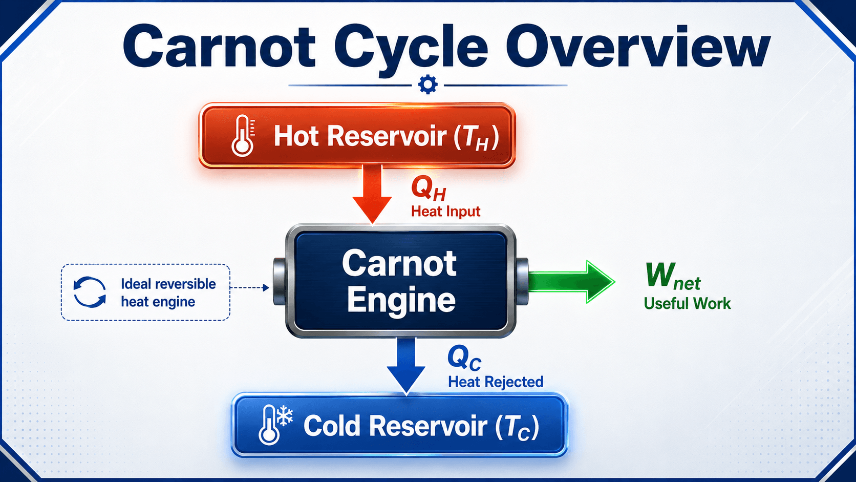
Notice the energy split first: not all heat input becomes useful work. Even the ideal Carnot engine must reject heat to the cold reservoir, which is why the Second Law sets a hard limit on heat-engine efficiency.
What is the Carnot Cycle?
The Carnot cycle is a theoretical heat-engine cycle made of four internally reversible processes. It describes a working fluid that absorbs heat at a high temperature, expands to produce work, rejects heat at a low temperature, and returns to its original state so the cycle can repeat.
The cycle is named after Sadi Carnot, whose work established a theoretical limit for converting heat into mechanical work. In modern thermodynamics, the Carnot cycle is less useful as a machine layout and more useful as a benchmark for understanding what no real heat engine can exceed.
The key idea is that a heat engine cannot convert all heat input into work over a complete cycle. Some heat must be rejected to a lower-temperature sink. The Carnot cycle shows the best possible case: all processes are reversible, no entropy is generated, and the only performance limit comes from the hot and cold reservoir temperatures.
The Carnot cycle is useful because it separates the theoretical limit from the practical machine. A real engine can be well-designed and still be far below Carnot efficiency because real heat transfer and real components generate entropy.
How the Carnot Cycle Works
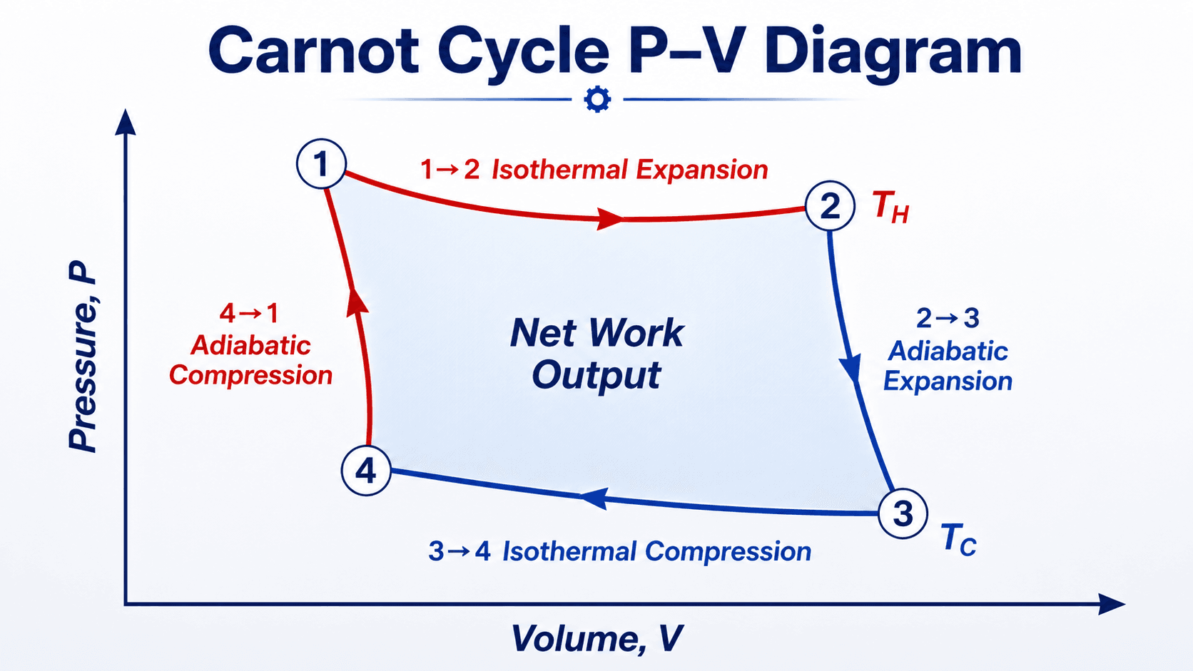
The Carnot cycle works by connecting two constant-temperature heat-transfer processes with two reversible adiabatic processes. In the heat-engine direction, the cycle is clockwise on a pressure-volume diagram and produces net work because expansion work is greater than compression work.
1 to 2: Isothermal Expansion at \(T_H\)
During isothermal expansion, the working fluid absorbs heat \(Q_H\) from the hot reservoir while remaining at the hot-reservoir temperature \(T_H\). The fluid expands and performs work. For an ideal gas model, internal energy depends only on temperature, so the heat added during this process is converted into boundary work.
2 to 3: Adiabatic Expansion
During adiabatic expansion, no heat crosses the system boundary. The working fluid continues expanding and doing work, but its temperature drops from \(T_H\) to \(T_C\). In the ideal Carnot cycle, this adiabatic process is also isentropic because it is reversible and has no heat transfer.
3 to 4: Isothermal Compression at \(T_C\)
During isothermal compression, the working fluid rejects heat \(Q_C\) to the cold reservoir while remaining at the cold-reservoir temperature \(T_C\). Work is done on the fluid, but the compression occurs at a lower pressure level than the expansion process, so the cycle can still produce net work overall.
4 to 1: Adiabatic Compression
During adiabatic compression, no heat transfer occurs and the working fluid temperature rises from \(T_C\) back to \(T_H\). In the ideal Carnot cycle, this process is also isentropic because the compression is reversible and adiabatic. At the end of the process, the system has returned to its initial state.
| Process | Type | Heat transfer | Work interaction | Temperature behavior | Entropy behavior |
|---|---|---|---|---|---|
| 1 → 2 | Isothermal expansion | Heat added, \(Q_H\) | Work produced by expansion | Constant at \(T_H\) | Entropy increases |
| 2 → 3 | Reversible adiabatic expansion | No heat transfer | Work produced by expansion | Drops from \(T_H\) to \(T_C\) | Entropy remains constant |
| 3 → 4 | Isothermal compression | Heat rejected, \(Q_C\) | Work input to compress fluid | Constant at \(T_C\) | Entropy decreases |
| 4 → 1 | Reversible adiabatic compression | No heat transfer | Work input to compress fluid | Rises from \(T_C\) to \(T_H\) | Entropy remains constant |
Why the Carnot Cycle Matters in Engineering
Engineers do not usually design machines to physically follow a perfect Carnot cycle. Instead, they use it as a limiting case that answers a critical question: how much work could a heat engine possibly produce between two temperature levels if all losses were removed?
- It gives the upper thermal-efficiency limit for a heat engine operating between \(T_H\) and \(T_C\).
- It explains why raising the hot-side temperature or lowering the cold-side temperature improves theoretical efficiency.
- It helps compare real cycles such as Rankine, Brayton, Otto, Diesel, and vapor-compression cycles against a reversible benchmark.
- It reinforces why waste heat is unavoidable in a cyclic heat engine.
If a proposed heat engine claims to convert all heat input into work over a cycle, it is not just unrealistic; it violates the Second Law requirement that a cyclic heat engine must reject heat to a lower-temperature sink.
Reversed Carnot Cycle for Refrigerators and Heat Pumps
The same ideal processes can be run in reverse. A forward Carnot cycle produces net work by receiving heat from a hot reservoir and rejecting heat to a cold reservoir. A reversed Carnot cycle requires net work input to move heat from a cold region to a warmer region.
This reversed direction is the ideal model behind refrigerators and heat pumps. Instead of thermal efficiency, engineers usually discuss coefficient of performance, or COP. The reversed Carnot cycle gives the best possible COP between two temperature reservoirs, just as the forward Carnot cycle gives the best possible heat-engine efficiency.
| Cycle direction | Energy objective | Work interaction | Common engineering interpretation |
|---|---|---|---|
| Forward Carnot cycle | Convert part of heat input into work | Net work output | Ideal heat engine |
| Reversed Carnot cycle | Move heat from cold to hot | Net work input | Ideal refrigerator or heat pump |
Key Factors That Control Carnot Cycle Performance
Carnot cycle performance is controlled by reservoir temperatures, reversibility, and the direction of heat and work interactions. The most important practical lesson is that temperature levels matter more than the amount of working fluid or the mechanical layout of a theoretical Carnot engine.
| Factor | Why it matters | Engineering implication |
|---|---|---|
| Hot-reservoir temperature, \(T_H\) | A higher \(T_H\) increases the theoretical fraction of heat input that can become work. | Gas turbines, boilers, and engines benefit from higher allowable operating temperatures, but materials and emissions often limit the hot side. |
| Cold-reservoir temperature, \(T_C\) | A lower \(T_C\) reduces the required heat rejection temperature and improves the theoretical efficiency limit. | Condensers, cooling towers, ambient air, river water, or seawater can strongly affect actual plant efficiency. |
| Reversibility | The Carnot limit assumes no entropy generation from friction, turbulence, mixing, or finite-temperature heat transfer. | Real equipment always departs from the ideal model, so Carnot efficiency should be treated as an upper bound, not a target operating value. |
| Heat-transfer temperature difference | Perfectly reversible heat transfer requires an infinitesimal temperature difference. | Real heat exchangers need finite temperature differences to transfer heat at useful rates, which creates irreversibility. |
| Cycle direction | The same ideal processes can run forward as a heat engine or in reverse as a refrigerator or heat pump. | Clockwise diagrams usually represent net work output; reversed cycles require net work input to move heat from cold to hot. |
Carnot Efficiency Formula
The efficiency of a Carnot heat engine depends only on the absolute temperatures of the hot and cold reservoirs. This is one reason the cycle is so important: it turns a complicated engine-performance question into a simple temperature-limit comparison.
In this equation, \(T_H\) and \(T_C\) must be absolute temperatures. Use Kelvin in SI work or Rankine in US customary work. Do not use degrees Celsius or degrees Fahrenheit directly in the ratio.
- \(\eta_{Carnot}\) Maximum theoretical heat-engine efficiency between the two reservoirs, expressed as a fraction or percent.
- \(T_H\) Hot-reservoir absolute temperature, usually in Kelvin or Rankine.
- \(T_C\) Cold-reservoir absolute temperature, usually in Kelvin or Rankine.
Why Carnot Efficiency Depends Only on Temperature
Thermal efficiency is the ratio of net work output to heat input. For a complete cycle, the net work output equals heat added minus heat rejected.
For a reversible Carnot cycle, the heat-transfer ratio equals the absolute temperature ratio:
Substituting this relationship into the efficiency equation gives the Carnot efficiency expression. That is why no details about engine size, piston geometry, working-fluid mass, or mechanical layout appear in the final ideal efficiency equation.
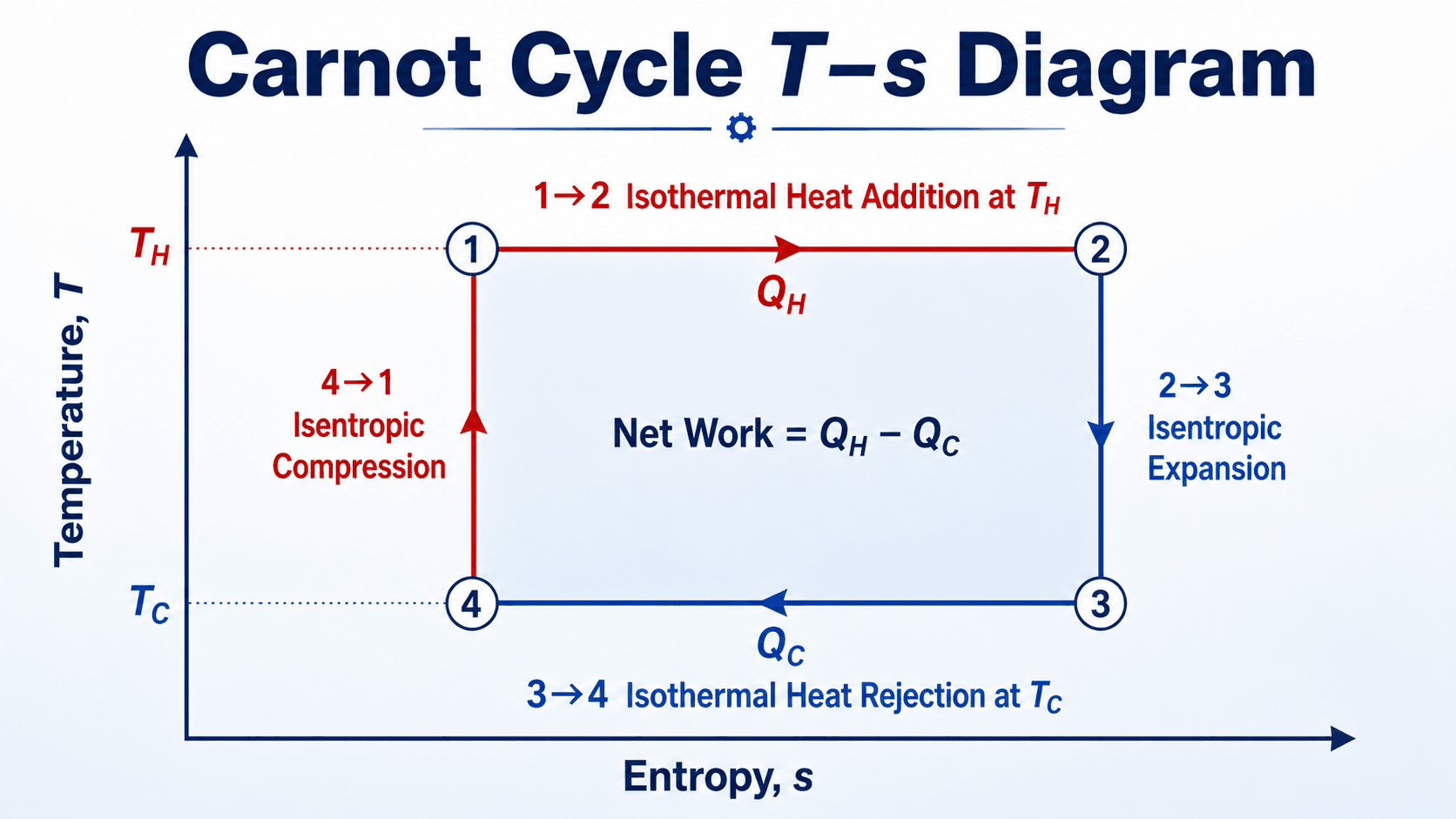
How to Read the T-s Diagram
For an internally reversible process, heat transfer can be represented on a T-s diagram. In the Carnot cycle, the entropy change during heat addition and heat rejection has the same magnitude, so the diagram becomes a rectangle.
This is the clearest visual reason Carnot efficiency depends on temperature. The width of the rectangle is tied to entropy change, while the height is tied to the temperature difference between the reservoirs.
The fastest way to spot a Carnot efficiency mistake is to check the temperature units. A result calculated with Celsius or Fahrenheit temperatures is usually wrong because the formula requires absolute temperature.
Carnot Cycle Analysis Workflow
Use this workflow when reviewing a Carnot cycle problem, comparing an ideal engine to a real cycle, or checking whether a proposed efficiency claim is thermodynamically reasonable.
Define the two reservoirs, convert both temperatures to an absolute scale, identify the cycle direction, calculate the ideal Carnot limit, then compare the result against the real equipment efficiency. If the real efficiency exceeds the Carnot limit, the inputs, units, or interpretation are wrong.
| Check or decision | What to look for | Why it matters |
|---|---|---|
| Temperature basis | Use Kelvin or Rankine for both \(T_H\) and \(T_C\). | Carnot efficiency is a ratio of absolute temperatures; non-absolute units distort the result. |
| Reservoir definition | Confirm the hot and cold reservoirs are the actual heat-addition and heat-rejection temperature levels. | Using flame temperature, room temperature, or working-fluid temperature at the wrong state can overstate or understate the limit. |
| Cycle direction | Check whether the diagram is a heat engine or a reversed cycle. | A forward Carnot cycle produces net work; a reversed Carnot cycle requires work input for refrigeration or heat pumping. |
| Realistic comparison | Compare actual equipment efficiency to the Carnot limit, not to 100%. | A low-looking real efficiency may be reasonable if the reservoir temperature difference gives a modest theoretical limit. |
| Loss mechanism review | Look for friction, pressure drop, heat leakage, non-isothermal heat transfer, and finite-rate processes. | These are the practical reasons real engines fall below the ideal reversible benchmark. |
Worked Example: Carnot Efficiency
Suppose an ideal heat engine operates between a hot reservoir at 600 K and a cold reservoir at 300 K. The maximum theoretical efficiency is:
Result
The Carnot efficiency is 0.50, or 50%. This means no heat engine operating between 600 K and 300 K can convert more than half of the heat input into net work, even before real-world losses are considered.
Engineering Meaning
If a real engine between those same reservoir temperatures achieved 35% thermal efficiency, that would not mean the remaining 65% is all poor design. The theoretical ceiling is already 50%, and practical losses reduce the achievable value below that limit.
Carnot Cycle vs Real Power Cycles
The Carnot cycle is often taught beside practical power cycles because it provides the ideal benchmark, not the real equipment layout. Real cycles use processes that are easier to approximate with turbines, compressors, pumps, condensers, boilers, pistons, valves, and heat exchangers.
| Cycle | Main use | Ideal process pattern | Why it differs from Carnot |
|---|---|---|---|
| Carnot cycle | Theoretical heat-engine limit | Two isothermal and two reversible adiabatic processes | Designed to maximize reversible efficiency, not to model practical equipment. |
| Rankine cycle | Steam power plants | Pumping, heat addition, expansion, and condensation | Uses phase change and practical boiler-condenser equipment rather than fully isothermal heat transfer. |
| Brayton cycle | Gas turbines and jet engines | Compression, heat addition, expansion, and heat rejection | Heat addition and rejection occur over temperature ranges, not at perfectly constant reservoir temperatures. |
| Otto cycle | Spark-ignition engines | Compression, idealized heat addition, expansion, and heat rejection | Represents internal combustion behavior with simplified constant-volume heat addition. |
| Vapor-compression refrigeration cycle | Refrigerators, air conditioners, chillers, and heat pumps | Compression, condensation, expansion, and evaporation | It is a practical reversed cycle with throttling and compressor losses, not a reversible Carnot refrigerator. |
Engineering Judgment and Field Reality
The Carnot cycle is a limit, not a buildable operating recipe. Reversible heat transfer would require the working fluid and reservoir to be at nearly the same temperature during heat exchange. That condition gives the best thermodynamic efficiency, but it also makes heat transfer extremely slow.
Real engines must produce useful power at finite rates. That requires real heat exchangers, compressors, expanders, combustion processes, bearings, valves, seals, and flow passages. Each one introduces entropy generation, pressure loss, heat leakage, mechanical friction, or non-ideal expansion and compression.
In the reversible limit, useful heat-transfer rates become impractically small unless heat exchangers become unrealistically large. Practical design is a tradeoff between efficiency, power density, cost, material limits, heat-transfer area, reliability, and operating range.
When This Breaks Down
The Carnot cycle becomes misleading when it is treated as a practical equipment model instead of a theoretical efficiency limit. It does not capture many of the details engineers need for real cycle design, component sizing, control logic, or performance prediction.
- Finite heat-transfer rates: Real heat exchangers need temperature differences, which create irreversibility.
- Component losses: Turbines, compressors, pistons, seals, valves, and bearings introduce friction and non-ideal behavior.
- Working-fluid limits: Real fluids have phase changes, property variation, critical points, chemical limits, and material compatibility constraints.
- Power output requirements: A cycle optimized only for reversible behavior may not produce useful power at a practical size or cost.
- Temperature constraints: Metallurgy, combustion limits, environmental conditions, cooling water availability, and safety margins often control real \(T_H\) and \(T_C\).
Common Mistakes and Practical Checks
Most Carnot cycle mistakes come from mixing ideal theory with real equipment interpretation. The cycle is simple mathematically, but it is easy to misuse when temperatures, diagram direction, or reservoir assumptions are unclear.
- Using Celsius or Fahrenheit in the efficiency equation: Always convert to Kelvin or Rankine before calculating \(\eta_{Carnot}\).
- Thinking Carnot efficiency is achievable: It is an upper limit for a reversible cycle, not a realistic performance target for real hardware.
- Confusing adiabatic and isothermal paths: Isothermal processes exchange heat at constant temperature; adiabatic processes have no heat transfer.
- Assuming all adiabatic processes are isentropic: In general, adiabatic only means no heat transfer. It is isentropic only when the process is also reversible.
- Ignoring cycle direction: A reversed Carnot cycle describes ideal refrigeration or heat pumping, not a work-producing engine.
- Using the wrong reservoir temperature: The limiting reservoirs are not always the same as a peak flame temperature or an average working-fluid temperature.
Never compare a real engine directly against 100% efficiency when the real theoretical limit is the Carnot efficiency between its actual hot and cold temperature reservoirs.
Useful References and Engineering Context
The Carnot cycle is a foundational thermodynamics model rather than a design code requirement. Engineers usually apply it through thermodynamics coursework, cycle analysis, equipment performance review, and second-law reasoning.
- NASA Glenn Research Center: NASA Glenn Carnot cycle explanation explains how the ideal cycle converts net heat transfer into useful work and relates the enclosed process area to work output.
- Project-specific criteria: Real engine, turbine, heat-pump, and refrigeration performance depends on equipment data, working-fluid properties, thermal limits, and operating conditions.
- Engineering use: Use the Carnot cycle as an upper-bound check before evaluating real cycles with component efficiencies, pressure losses, heat-exchanger approach temperatures, and measured performance data.
Frequently Asked Questions
The Carnot cycle is an ideal reversible thermodynamic cycle that sets the maximum possible efficiency for a heat engine operating between a hot reservoir and a cold reservoir. It is made of two isothermal processes and two adiabatic, or isentropic, processes.
The four Carnot cycle processes are isothermal expansion, adiabatic expansion, isothermal compression, and adiabatic compression. Together, they return the working fluid to its original state while producing net work in the ideal heat-engine direction.
Temperatures must be in Kelvin, or Rankine for US customary work, because Carnot efficiency uses a ratio of absolute temperatures. Celsius and Fahrenheit have arbitrary zero points, so using them directly produces physically incorrect efficiency values.
On a P-V diagram, the area enclosed by the clockwise Carnot cycle represents net work output. On a T-s diagram, the rectangle helps show heat added at the hot temperature, heat rejected at the cold temperature, and the net work difference.
A real engine cannot perfectly operate on the Carnot cycle because reversible heat transfer would require infinitesimally small temperature differences and ideal processes with no losses. The Carnot cycle is best used as a theoretical benchmark for comparing real heat engines.
Summary and Next Steps
The Carnot cycle is the ideal reversible heat-engine cycle used to define the maximum possible efficiency between a hot reservoir and a cold reservoir. It is built from isothermal expansion, reversible adiabatic expansion, isothermal compression, and reversible adiabatic compression.
The most important practical habit is to treat Carnot efficiency as a ceiling, not a real operating value. Convert temperatures to an absolute scale, identify the correct reservoirs, check the cycle direction, and then compare real equipment against the Carnot limit while accounting for irreversibility.
Where to go next
Continue your learning path with related Turn2Engineering resources.
-
Second Law of Thermodynamics
Learn why heat engines require rejected heat and why real processes generate entropy.
-
Entropy
Understand the property most closely tied to reversibility, irreversibility, and lost useful work.
-
Heat Engines
See how real engines convert heat into work and why their efficiency falls below the ideal limit.