Key Takeaways
- Core idea: Crystallography studies the ordered arrangement of atoms, ions, or molecules in crystalline materials.
- Engineering use: It helps explain strength, ductility, conductivity, thermal expansion, optical response, phase identity, and fracture behavior.
- What controls it: Unit cell geometry, crystal symmetry, planes, directions, grain orientation, phase composition, and defects all affect performance.
- Practical check: Ideal crystal diagrams are useful, but real materials include grains, dislocations, impurities, texture, residual stress, and processing history.
Table of Contents
Introduction
Crystallography is the study of how atoms, ions, or molecules are arranged in crystalline materials and how that ordered structure affects material behavior. In materials science, crystallography connects atomic geometry to engineering properties such as strength, ductility, conductivity, thermal expansion, optical behavior, phase identity, and fracture response.
Crystal Lattice, Unit Cell, and Basis
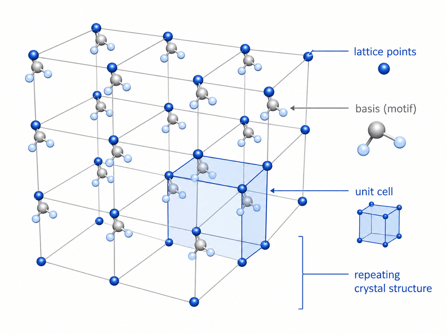
Notice that the unit cell is not the entire material. It is a compact way to represent the repeating atomic arrangement that extends through a crystal or grain.
What Is Crystallography?
Crystallography describes the internal order of crystalline materials. Instead of treating a material as a uniform solid, it looks at how atoms are arranged, how that pattern repeats, and how the arrangement produces measurable properties. This is why crystallography is central to materials science, metallurgy, ceramics, semiconductors, minerals, and many advanced engineering materials.
Crystallography does not simply test whether a material is strong or weak; it helps explain the ordered structure that contributes to those measured properties. Atomic packing, bonding direction, crystallographic planes, and grain orientation can affect how a material deforms, conducts heat, conducts electricity, transmits light, corrodes, fractures, or changes phase during processing.
Most introductory crystallography examples use periodic crystals because they are easier to visualize. More advanced crystallography can also include ordered aperiodic structures, such as quasicrystals, where long-range order exists without a simple repeating three-dimensional unit cell.
Two materials can have the same chemical elements but different crystal structures, phases, grain orientations, or defect populations. Those differences can create very different engineering behavior even when the chemistry looks similar.
Crystal Structure Terms Engineers Need to Know
Crystallography has several terms that sound similar but describe different parts of the structure. Keeping these terms separate makes later topics, such as Miller indices and X-ray diffraction, much easier to understand.
| Term | What it means | Why it matters in materials science |
|---|---|---|
| Crystal | A solid with long-range atomic, ionic, or molecular order. | Ordered structure creates predictable planes, directions, symmetry, and diffraction behavior. |
| Lattice | A repeating geometric framework of points in space. | It defines the repeating pattern but does not fully describe which atoms occupy the pattern. |
| Basis or motif | The atom, ion, molecule, or group attached to each lattice point. | The basis turns a geometric lattice into an actual crystal structure. |
| Unit cell | The smallest repeatable volume used to describe the crystal. | It lets engineers describe complex atomic order using dimensions, angles, and atomic positions. |
| Crystal structure | The complete repeating arrangement of atoms in the material. | It links atomic-scale geometry to properties such as slip, cleavage, conductivity, and diffraction. |
| Symmetry | The repeated geometric relationships that remain unchanged after certain rotations, reflections, translations, or inversions. | Symmetry helps classify crystals and affects planes, directions, physical properties, and diffraction patterns. |
| Bravais lattice | One of the unique three-dimensional lattice types based on symmetry and centering. | Bravais lattices refine crystal-system geometry and help organize diffraction and structure descriptions. |
| Grain | A region of material where the crystal lattice has one general orientation. | Most engineering metals and ceramics are polycrystalline, so grain size and orientation matter. |
Crystallography vs X-Ray Crystallography vs XRD
Many readers use crystallography, X-ray crystallography, and X-ray diffraction as if they mean the same thing. They are closely related, but they are not identical. Crystallography is the broader field, while X-ray diffraction is one major method used to study crystalline structure.
| Term | Meaning | Best use |
|---|---|---|
| Crystallography | The broad study of crystalline structure, symmetry, atomic arrangement, and related properties. | Understanding how structure connects to material properties, phases, and engineering performance. |
| X-ray crystallography | A crystallographic method that uses X-ray diffraction to determine atomic or molecular structure. | Determining detailed structures of crystals, molecules, minerals, and engineered materials. |
| X-ray diffraction (XRD) | A practical measurement method that records how X-rays scatter from crystal planes. | Identifying phases, estimating interplanar spacing, reviewing texture, and comparing crystal structures. |
XRD is one crystallographic method, not the entire field of crystallography. Crystallography also includes symmetry, structure determination, crystal chemistry, diffraction theory, and interpretation of ordered materials.
Crystal Systems, Bravais Lattices, and Common Engineering Structures
Crystal systems classify unit cells by their edge lengths and angles. This geometry controls how atoms pack together and helps engineers compare structures such as simple cubic, body-centered cubic, face-centered cubic, and hexagonal close-packed materials.
The 7 crystal systems
| Crystal system | General geometry | Engineering relevance |
|---|---|---|
| Cubic | Equal edge lengths and right angles. | Common in many metals and ceramics; includes BCC and FCC structures. |
| Tetragonal | Two equal edge lengths, one different, with right angles. | Appears in some ceramics, minerals, and phase-transformed materials. |
| Orthorhombic | Three unequal edge lengths with right angles. | Useful in many crystalline compounds where symmetry affects directional behavior. |
| Hexagonal | Two equal in-plane axes with a third different axis. | Important for HCP metals such as magnesium, titanium, and zinc. |
| Trigonal | Threefold symmetry with non-cubic geometry. | Appears in minerals and some functional materials. |
| Monoclinic | Unequal axes with one non-right angle. | Common in lower-symmetry crystals and some polymers or ceramics. |
| Triclinic | Unequal axes with no required right angles. | Lowest symmetry; often requires careful structural interpretation. |
Where Bravais lattices fit
The 7 crystal systems describe broad unit-cell geometry. Bravais lattices refine that idea into 14 unique three-dimensional lattice types based on symmetry and centering. For an engineering overview, the main point is that crystal symmetry and centering affect how planes, directions, and diffraction patterns are indexed.
BCC, FCC, and HCP in engineering materials
In engineering, the most useful starting point is often not the full crystal-system list but the structure family. For example, FCC metals generally have many active slip systems and are often ductile. BCC metals can show strong temperature-dependent deformation behavior. HCP metals can be more directionally limited because fewer easy slip systems may be available at room temperature.
| Structure | Typical examples | Practical implication |
|---|---|---|
| Body-centered cubic (BCC) | Ferritic iron, chromium, tungsten | Can provide high strength, but deformation behavior may be more temperature sensitive. |
| Face-centered cubic (FCC) | Aluminum, copper, nickel, austenitic stainless steel | Often supports ductile forming because close-packed planes allow easier slip. |
| Hexagonal close-packed (HCP) | Magnesium, titanium, zinc | Can show strong anisotropy and formability limits depending on texture and temperature. |
| Simple cubic | Less common as a pure engineering-metal structure | Useful as a teaching model for understanding unit cells and coordination. |
These trends are useful starting points, but alloy chemistry, temperature, grain size, heat treatment, and processing route can override simple structure-based expectations.
Miller Indices, Crystal Planes, and Directions
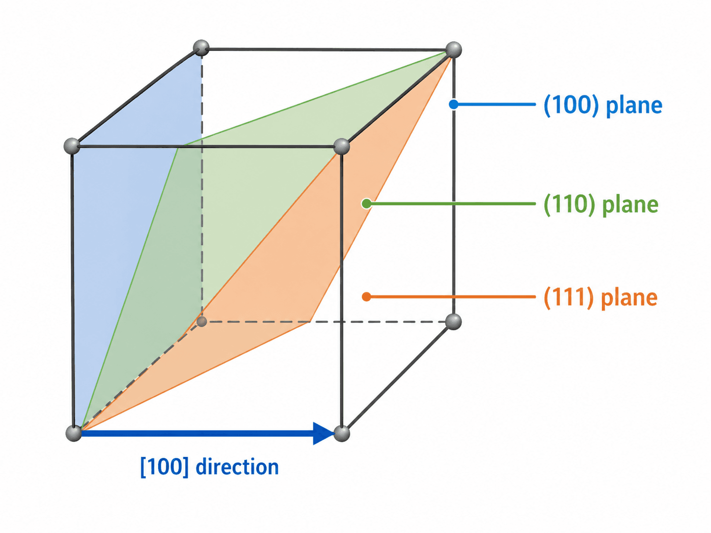
Miller indices are a notation system used to describe planes and directions inside a crystal. Planes are usually written with parentheses, such as \((100)\), \((110)\), or \((111)\). Directions are usually written with square brackets, such as \([100]\). This notation matters because planes and directions often control deformation, cleavage, surface behavior, and diffraction.
Simple Miller indices example
In a cubic unit cell, the \((100)\) plane cuts one axis and remains parallel to the other two. The \((110)\) plane cuts two axes and stays parallel to the third. The \((111)\) plane cuts all three axes, which is why it appears as a diagonal plane through the cube.
Why planes and directions matter
Many material behaviors are directional. A crystal may deform more easily along one family of planes than another, fracture along preferred cleavage planes, or conduct heat and electricity differently depending on orientation. In a single crystal, directionality can be obvious. In a polycrystalline material, the combined orientation of many grains creates the bulk response.
A drawing of one unit cell can make a material look perfectly uniform, but manufactured parts usually contain many grains with different orientations. Rolling, extrusion, forging, welding, heat treatment, and additive manufacturing can all create texture that makes crystallographic direction important at the part scale.
How X-Ray Diffraction Uses Crystallography
X-ray diffraction, often shortened to XRD, is one of the most common ways to study crystalline materials. When X-rays interact with regularly spaced crystal planes, the scattered waves can reinforce one another at specific angles. The resulting diffraction peaks help identify phases, estimate interplanar spacing, and compare crystal structures.
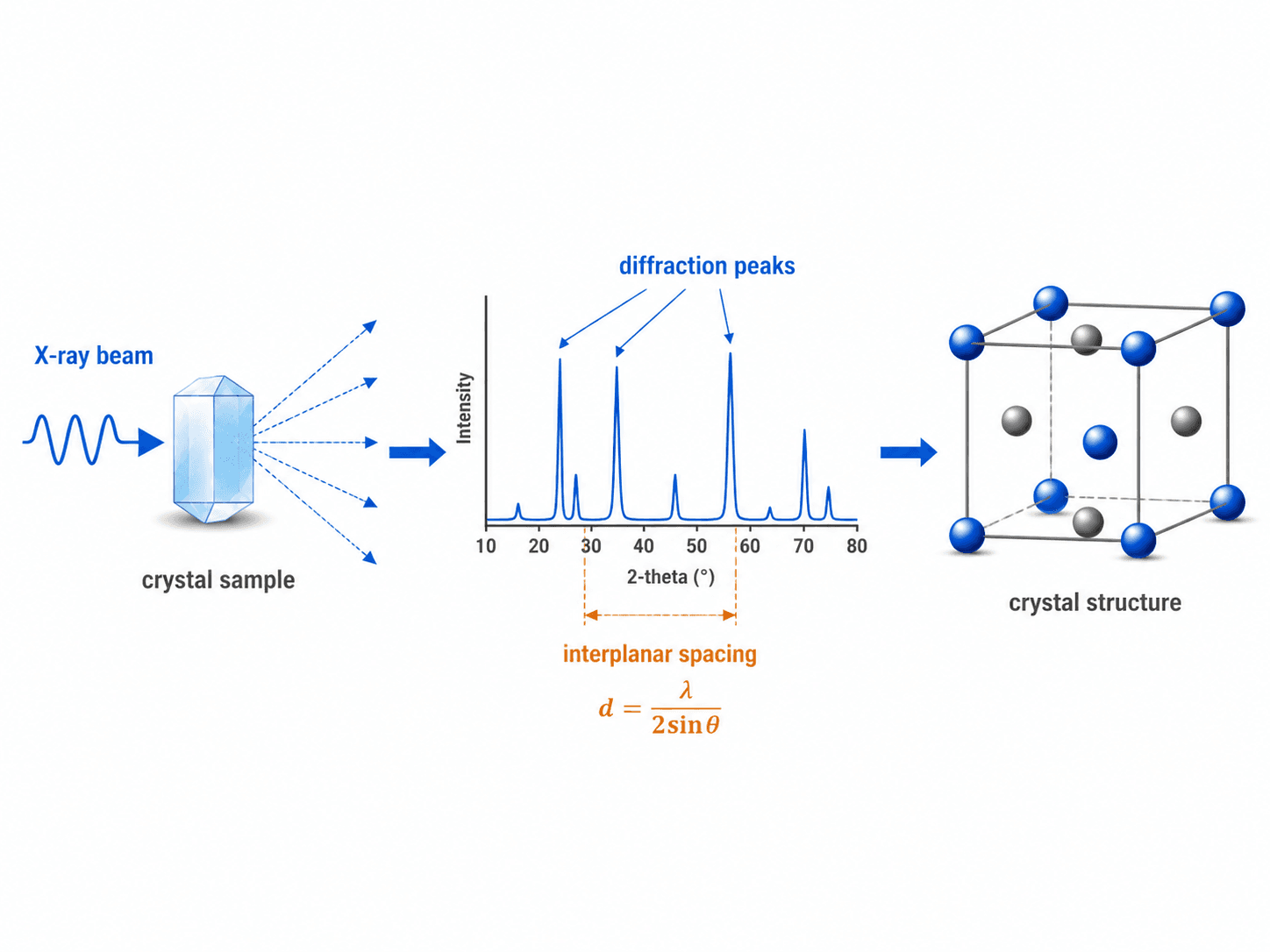
A common relationship used to interpret diffraction is Bragg’s law:
- \(n\) Diffraction order, commonly treated as 1 in basic XRD interpretation.
- \(\lambda\) X-ray wavelength, controlled by the instrument source.
- \(d\) Interplanar spacing between a family of crystal planes.
- \(\theta\) Diffraction angle associated with constructive interference from crystal planes.
Simple XRD interpretation example
If two samples have the same chemistry but show different diffraction peak positions or intensities, the difference may indicate a different phase, preferred orientation, residual strain, or processing history. Engineers use the pattern as structural evidence, then compare it with material specifications, microscopy, hardness data, or other tests before making a final conclusion.
The important engineering idea is not just the equation. The peak locations, peak intensities, and peak widths can provide clues about phase composition, preferred orientation, crystallite size, strain, and processing history. Interpretation still requires judgment because overlapping peaks, multiphase materials, surface preparation, and instrument settings can all affect the pattern.
Crystalline vs Amorphous Materials
Crystallography is most directly useful when a material has long-range order. Some materials are highly crystalline, some are amorphous, and many engineering materials fall between those extremes. This distinction matters because unit cells, Miller indices, and diffraction patterns do not apply the same way to every solid.
| Material type | Atomic arrangement | Crystallography relevance | Engineering implication |
|---|---|---|---|
| Crystalline | Long-range ordered arrangement. | Unit cells, crystal planes, Miller indices, and diffraction patterns apply strongly. | Directionality, phase identity, slip systems, cleavage, and XRD interpretation matter. |
| Polycrystalline | Many crystalline grains with different orientations. | Each grain has crystal structure, but bulk behavior depends on grain size and texture. | Most engineering metals and ceramics fall into this category. |
| Amorphous | No simple long-range repeating crystal structure. | Classic unit-cell and Miller-index descriptions do not apply the same way. | Glasses and some polymers behave differently from crystalline solids. |
| Semi-crystalline | Mixture of crystalline and amorphous regions. | Crystallinity fraction and morphology become important. | Common in polymers where processing can change stiffness, toughness, and thermal behavior. |
How Crystal Structure Affects Material Properties
Crystallography helps explain why material properties are not determined by chemistry alone. Atomic arrangement affects bonding direction, packing density, slip behavior, phase stability, and the way energy moves through a material. That makes crystallography a foundation for understanding broader material properties.
| Property category | Crystallography connection | Engineering implication |
|---|---|---|
| Mechanical behavior | Slip planes, dislocations, packing density, and grain orientation affect strength and ductility. | Crystal structure helps explain why some metals form easily while others crack or require hot working. |
| Thermal behavior | Atomic spacing, bonding, and crystal symmetry influence heat flow and thermal expansion. | Direction-dependent expansion can create residual stress, distortion, or cracking in constrained parts. |
| Electrical behavior | Crystal structure and defects affect electron mobility, band behavior, and scattering. | Semiconductors, conductors, and insulators depend heavily on atomic order and impurity control. |
| Optical behavior | Symmetry and orientation can influence refraction, birefringence, transparency, and scattering. | Crystallography matters in lenses, laser crystals, sensors, ceramics, and transparent materials. |
| Chemical behavior | Surface planes, defects, and phase boundaries affect reactivity and corrosion behavior. | Different crystal faces of the same material may react or corrode at different rates. |
| Magnetic behavior | Crystal symmetry and atomic arrangement influence magnetic anisotropy and domain behavior. | Magnetic materials may perform differently depending on orientation and processing history. |
This is why crystallography is part of the structure-properties-processing-performance relationship in materials science. A design problem rarely depends on only one property; it depends on how structure, processing, defects, and service environment work together.
Real Materials Are Not Perfect Crystals
Textbook crystallography often starts with perfect repeating structures, but engineering materials are rarely perfect. Metals are usually polycrystalline, ceramics can contain pores and secondary phases, semiconductors may be engineered with controlled impurities, and manufactured parts can contain residual stress, inclusions, or texture.
| Real-material feature | What it changes | Why engineers care |
|---|---|---|
| Dislocations | Enable plastic deformation and interact with strengthening mechanisms. | They help explain yielding, work hardening, and many strengthening processes. |
| Grain boundaries | Interrupt crystal continuity between neighboring grains. | They affect strength, toughness, corrosion, diffusion, creep, and fracture paths. |
| Texture | Creates preferred grain orientation after processing. | It can make sheet metal, extrusions, and additively manufactured parts direction-dependent. |
| Second phases | Add different crystal structures or compositions within the same material. | They can strengthen alloys, embrittle materials, or control wear and high-temperature performance. |
| Residual stress | Changes the stress state without changing the nominal external load. | It can shift diffraction peaks, affect fatigue life, and cause distortion or cracking. |
Crystallography explains the ordered structure, but engineering performance also depends on defects, grain size, processing history, environment, and loading. A crystal structure alone is rarely enough to approve a material for service.
Crystallography Review Checklist for Materials Engineering
Use this checklist when crystallography is being used to explain a material property, interpret a diffraction result, compare phases, or review a material selection decision.
Start with the crystal structure, identify the relevant planes or directions, check whether the material is single-crystal, polycrystalline, amorphous, or semi-crystalline, then connect the structure to the property being evaluated. Finally, review defects, grain structure, phase composition, processing history, and measurement limitations before drawing conclusions.
| Review check | What to look for | Why it matters |
|---|---|---|
| Crystal structure | Identify whether the material is FCC, BCC, HCP, ceramic, ionic, covalent, molecular, amorphous, or another structure type. | Structure gives the first clue about slip, bonding, packing density, and property directionality. |
| Property being explained | Identify whether the target property is mechanical, thermal, electrical, optical, chemical, magnetic, or related to failure. | Crystallography should be interpreted differently depending on the property, environment, and loading condition. |
| Plane and direction relevance | Check whether specific planes or directions control deformation, cleavage, surface behavior, or diffraction peaks. | Miller indices are most useful when tied to a physical behavior, not treated as notation only. |
| Phase composition | Confirm whether the material is single-phase, multiphase, transformed, precipitated, or partially amorphous. | Different phases can dominate strength, corrosion, toughness, and thermal behavior. |
| Grain orientation and texture | Look for rolling direction, extrusion direction, additive-build direction, or preferred orientation in XRD results. | Texture can make bulk properties direction-dependent even when chemistry is unchanged. |
| Defects and boundaries | Consider dislocations, vacancies, grain boundaries, inclusions, pores, and residual stress. | Real defects often control failure more than the ideal unit cell does. |
| Measurement method | Check whether the conclusion came from XRD, electron diffraction, microscopy, database lookup, or simulation. | Each method has limits in resolution, sampling depth, phase detection, and interpretation confidence. |
What Crystallography Can and Cannot Tell You
Crystallography is powerful, but it should be used as part of a broader materials evaluation. It can explain structure and provide clues about properties, but it does not replace mechanical testing, chemical analysis, microscopy, environmental exposure testing, or service-specific qualification.
| Crystallography can help identify | Crystallography alone usually cannot confirm |
|---|---|
| Crystal structure, lattice type, symmetry, and phase identity. | Full part-level strength, toughness, fatigue life, or corrosion life. |
| Preferred orientation, texture, and crystallographic directionality. | Whether a manufactured component meets every service requirement. |
| Interplanar spacing, peak shifts, phase changes, and residual strain indicators. | The complete cause of a field failure without supporting evidence. |
| Whether a material is crystalline, amorphous, multiphase, or partially transformed. | All defects, inclusions, pores, cracks, or local manufacturing flaws. |
When This Breaks Down
Crystallography becomes less straightforward when the material is not well represented by a simple, perfect, repeating unit cell. The concept still matters, but the interpretation needs more care.
- Amorphous materials: Glasses and many polymers lack long-range crystalline order, so classic crystal-plane descriptions may not apply.
- Multiphase alloys: A measured property may be controlled by phase mixtures, precipitates, grain boundaries, and interfaces rather than one ideal crystal structure.
- Nanocrystalline materials: Grain boundaries become a large fraction of the material, so boundary behavior can dominate bulk properties.
- Highly textured materials: Rolling, extrusion, drawing, or additive manufacturing can make properties strongly direction-dependent.
- Diffraction interpretation limits: Peak overlap, preferred orientation, residual stress, low crystallinity, or poor sample preparation can make XRD patterns misleading.
Do not assume that identifying a crystal structure automatically predicts engineering performance. Processing, microstructure, defects, and environment can completely change how the material behaves in service.
Common Mistakes and Practical Checks
Many crystallography mistakes come from treating diagrams as literal pictures of real materials. Unit cells are models, Miller indices are notation, and diffraction patterns require interpretation.
| Common mistake | Why it causes problems | Better engineering check |
|---|---|---|
| Confusing lattice with crystal structure | The lattice is only the repeating geometry, not the full atomic arrangement. | Ask what basis or atoms occupy the lattice points. |
| Treating all crystals as isotropic | Single crystals and textured polycrystals can behave differently by direction. | Check orientation, texture, and whether directional properties matter. |
| Ignoring grain boundaries | Bulk parts are often polycrystalline, and grain boundaries can control strength, corrosion, creep, and fracture. | Review grain size, processing route, and heat treatment condition. |
| Overreading an XRD peak pattern | Peak positions alone may not resolve all phases, stresses, or textures. | Consider peak shape, intensity, sample preparation, and complementary testing. |
| Using ideal structures to explain service failures alone | Failures often depend on cracks, inclusions, corrosion, fatigue, creep, or local manufacturing defects. | Connect crystallography with broader material behavior, test data, microscopy, and failure analysis. |
Useful Crystallography Reference
Crystallography uses precise terminology, so authoritative definitions matter. Terms such as crystal, lattice, unit cell, symmetry, Miller indices, and diffraction have specific meanings that should be used consistently in technical communication.
- International Union of Crystallography: IUCr Online Dictionary of Crystallography provides definitions for crystallographic terms and helps keep language consistent when discussing crystal structures, planes, diffraction, symmetry, and related concepts.
- Engineering use: Use precise crystallography terminology when comparing phases, interpreting diffraction results, reviewing material data, or communicating with labs and suppliers.
- Project-specific criteria: Final material decisions should also consider applicable specifications, processing route, test data, service environment, and part-level performance requirements.
Frequently Asked Questions
Crystallography is the study of how atoms, ions, or molecules are arranged in crystalline materials. In engineering, it helps explain why materials have different strength, ductility, conductivity, thermal behavior, optical response, and failure behavior.
Crystallography is important because material properties often depend on atomic arrangement, crystal structure, crystallographic planes, phase composition, grain orientation, and defects. It connects microscopic structure to real engineering performance.
Crystallography is the broader study of crystalline structure and properties. X-ray diffraction, or XRD, is one method used to study crystalline materials by measuring how X-rays scatter from crystal planes.
Miller indices are used to describe crystallographic planes and directions inside a crystal. They matter for slip, cleavage, diffraction, grain orientation, surface behavior, and understanding why some material properties vary by direction.
Classic crystallography is most useful for materials with long-range crystalline order. Amorphous materials, such as glass, lack the same repeating unit-cell structure, although their short-range atomic arrangement can still be studied with other structural methods.
Summary and Next Steps
Crystallography explains the ordered atomic structure of crystalline materials. It gives engineers a way to understand unit cells, crystal systems, Bravais lattices, Miller indices, diffraction patterns, and the structural reasons materials behave differently.
The most useful engineering view is to connect crystallography with material properties, processing, grain structure, defects, and service conditions. A perfect unit cell is a starting model, not the full story of how a real part performs.
Where to go next
Start with atomic structure, then move into material properties and mechanical behavior depending on whether you want the theory path or the application path.
-
Atomic Structure
Review the electrons, bonding, and atomic-level behavior that create the foundation for crystal structures.
-
Material Properties
See how structure connects to mechanical, thermal, electrical, chemical, optical, magnetic, and acoustic behavior.
-
Mechanical Properties
Learn how strength, ductility, hardness, toughness, and fatigue resistance are affected by material structure and processing.