Key Takeaways
- Core idea: The vapor compression cycle moves heat from a cold region to a warmer region by adding compressor work to a circulating refrigerant.
- Engineering use: It is the basic thermodynamic cycle behind most refrigerators, air conditioners, heat pumps, cold rooms, and vapor-compression chillers.
- What controls it: Evaporator temperature, condenser temperature, refrigerant properties, compressor efficiency, pressure drop, superheat, and subcooling control performance.
- Practical check: A clean diagram is useful, but real systems must be checked for liquid floodback, high discharge temperature, restricted airflow, and unrealistic COP assumptions.
Table of Contents
Introduction
The vapor compression cycle is a closed refrigeration cycle that uses a refrigerant to absorb heat at low pressure, compresses the vapor to a higher pressure, rejects heat in a condenser, and passes through a throttling device before returning to the evaporator. It is the working principle behind most air conditioners, refrigerators, heat pumps, and chillers.
Vapor Compression Cycle Diagram
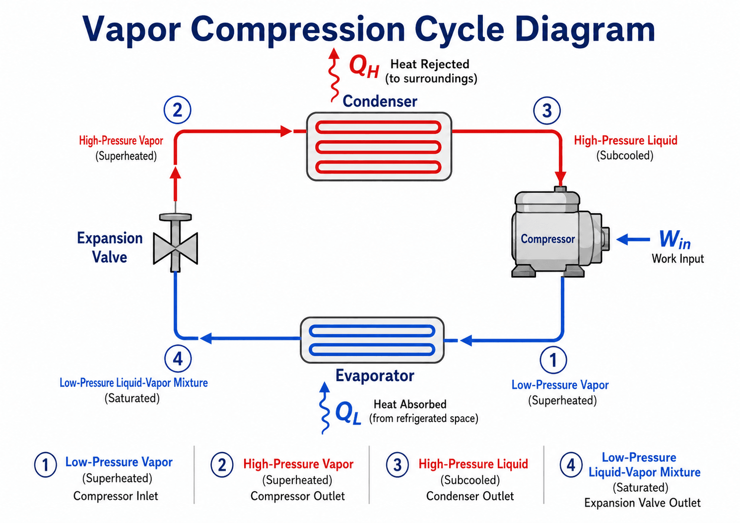
Start by following the refrigerant around the loop. The low-pressure side is where useful cooling occurs, while the high-pressure side is where the refrigerant rejects heat to the surroundings.
What Is the Vapor Compression Cycle?
The vapor compression cycle is a thermodynamic cycle that transfers heat from a lower-temperature region to a higher-temperature region by circulating a refrigerant through pressure and phase changes. The cycle is called “vapor compression” because the compressor handles refrigerant vapor, raises its pressure, and makes it hot enough to reject heat in the condenser.
In refrigeration textbooks, the same concept is often called the vapor compression refrigeration cycle or VCRS. It is the most common practical example within broader refrigeration cycles because it is compact, controllable, scalable, and well suited for air conditioning, food storage, process cooling, and heat pumps.
The cycle does not create “cold.” It uses work input to move heat against its natural direction, from a colder source to a warmer sink.
Four Main Components of the Vapor Compression Cycle
A basic vapor compression system has four major components. Each one changes the refrigerant in a specific way so the cycle can absorb heat at a low temperature and reject heat at a higher temperature.
Compressor
The compressor receives low-pressure refrigerant vapor from the evaporator and raises it to a higher pressure and temperature. This is the work-input device in the cycle, and it is usually the largest electrical load in the system.
Condenser
The condenser rejects heat from the high-pressure refrigerant to outdoor air, cooling water, or another heat sink. The refrigerant usually enters as superheated vapor and leaves as high-pressure liquid, often with some subcooling.
Expansion Valve or Metering Device
The expansion valve, capillary tube, or electronic expansion valve drops the refrigerant pressure before the evaporator. This is a throttling process, not a useful work-producing expansion process, so it is commonly modeled as \(h_3 \approx h_4\).
Evaporator
The evaporator absorbs heat from the cooled air, water, glycol, product, or process fluid. The low-pressure refrigerant boils inside the evaporator and normally leaves as vapor with controlled superheat.
How the Vapor Compression Cycle Works
A standard vapor compression refrigeration cycle is usually described using four state points. The numbering convention is commonly compressor inlet, compressor outlet, condenser outlet, and expansion valve outlet. Each part of the loop changes the refrigerant’s pressure, temperature, phase, or energy content.
1 → 2: Compression
Low-pressure refrigerant vapor enters the compressor and leaves as high-pressure, high-temperature vapor. In an ideal analysis, this step is often modeled as approximately isentropic. In a real compressor, motor losses, friction, leakage, and non-ideal gas behavior raise the required work input.
2 → 3: Condensation and Heat Rejection
The hot high-pressure vapor enters the condenser and rejects heat to outdoor air, cooling water, or another heat sink. The refrigerant usually desuperheats first, condenses through a two-phase region, and may leave slightly subcooled as a high-pressure liquid.
3 → 4: Throttling Through the Expansion Device
The liquid refrigerant passes through an expansion valve, capillary tube, or other metering device. Pressure drops sharply, some liquid flashes into vapor, and the refrigerant temperature falls. This process is usually modeled as isenthalpic, so \(h_3 \approx h_4\).
4 → 1: Evaporation and Heat Absorption
The cold low-pressure liquid-vapor mixture enters the evaporator and absorbs heat from air, water, food storage, process fluid, or another cooled medium. The refrigerant boils and normally leaves as vapor with a small amount of superheat to protect the compressor.
Vapor Compression Cycle on a T-s Diagram
A temperature-entropy diagram helps show how the vapor compression cycle moves through the saturation dome. It is especially useful for seeing heat absorption, heat rejection, and the difference between an ideal compression process and a real irreversible compression process.
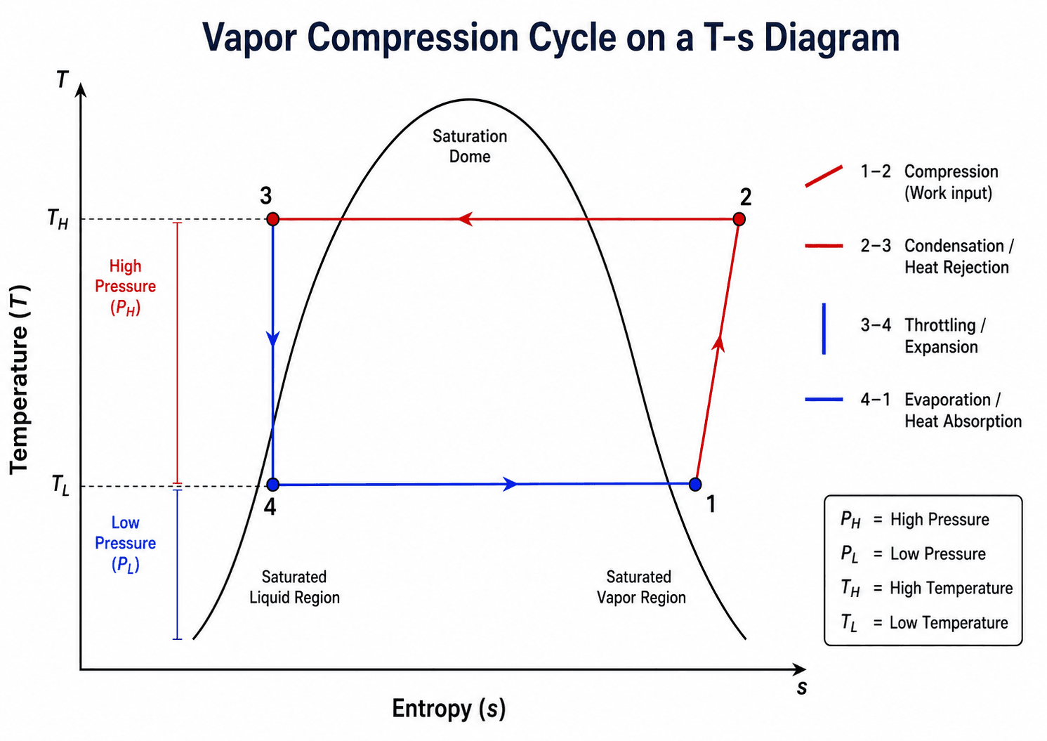
On a simplified T-s diagram, the evaporation and condensation portions often appear near constant-temperature lines because phase change occurs at nearly constant temperature for a fixed pressure. Actual systems deviate because of pressure drop, heat exchanger approach temperatures, superheating, subcooling, and compressor inefficiency.
On a real T-s diagram, compression usually leans to the right because entropy increases, and the condenser and evaporator paths are not perfectly flat once pressure drop, heat transfer temperature differences, superheat, and subcooling are included.
Vapor Compression Cycle on a P-h Diagram
A pressure-enthalpy diagram is the most practical chart for refrigeration calculations because enthalpy differences directly give compressor work, cooling effect, and heat rejection per unit mass of refrigerant.
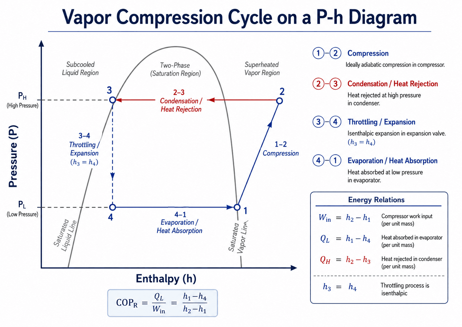
The throttling process is especially easy to identify on a P-h diagram because it is approximately constant enthalpy. That is why the vertical 3 → 4 line is one of the most important features to check when reading a refrigeration chart.
Vapor Compression Cycle vs Refrigeration Cycle vs Heat Pump Cycle
The same physical loop can be described in different ways depending on the application. The terminology usually changes based on which side of the cycle is useful to the user.
| Term | What it usually means | Useful output |
|---|---|---|
| Vapor compression cycle | The general thermodynamic cycle using compression, condensation, throttling, and evaporation. | Depends on whether the system is used for cooling or heating. |
| Vapor compression refrigeration cycle | The cooling-focused use of the same cycle, often abbreviated as VCRS. | Heat absorbed in the evaporator, \(q_L\). |
| Air conditioning cycle | A comfort-cooling application of the vapor compression refrigeration cycle. | Indoor heat removal and humidity control. |
| Heat pump cycle | A heating-focused use of vapor compression equipment, often with a reversing valve. | Heat rejected at the condenser, \(q_H\). |
Unlike the Carnot Cycle, the practical vapor compression cycle normally uses a throttling device instead of an ideal expander that recovers work. This makes the system simpler and cheaper, but it also introduces irreversibility.
Where Engineers Use the Vapor Compression Cycle
Engineers use the vapor compression cycle to estimate cooling capacity, compressor power, heat rejection, refrigerant mass flow rate, heat exchanger loading, equipment selection, and operating efficiency. The same cycle logic appears in small residential systems and large industrial refrigeration plants.
| Application | What the evaporator cools | Where heat is rejected |
|---|---|---|
| Household refrigerator | Food compartment air | Room air through a condenser coil |
| Air conditioner | Indoor air | Outdoor air at the condenser |
| Heat pump in heating mode | Outdoor air, ground loop, or water source | Indoor air through the indoor coil |
| Chiller | Water or glycol loop | Outdoor air, cooling tower water, or condenser water loop |
| Industrial refrigeration | Product, process load, cold room, or freezer space | Air-cooled, water-cooled, or evaporative condenser |
Common vapor compression refrigerants include hydrofluorocarbons, hydrofluoroolefins, ammonia, carbon dioxide, and hydrocarbons. Refrigerant selection depends on pressure level, temperature range, safety classification, environmental requirements, equipment compatibility, oil behavior, and application type.
Always identify the useful output before calculating performance. For refrigeration, the useful output is usually \(q_L\). For heat pumps, it is usually \(q_H\).
Key Factors That Control Cycle Performance
The performance of a vapor compression cycle depends on more than the four idealized components. The evaporating temperature, condensing temperature, compressor efficiency, heat exchanger condition, refrigerant choice, and controls all affect capacity and COP.
| Factor | Why it matters | Engineering implication |
|---|---|---|
| Evaporator temperature | Lower evaporator temperature usually increases compressor lift and reduces COP. | Cooling systems should not be operated colder than the load actually requires. |
| Condenser temperature | Higher condensing temperature raises compressor work and discharge temperature. | Dirty condenser coils, poor airflow, warm cooling water, or undersized condensers can reduce efficiency quickly. |
| Compressor efficiency | Real compression is irreversible and requires more work than the ideal process. | Isentropic efficiency and motor efficiency are essential when estimating actual power input. |
| Superheat | Superheat helps ensure vapor enters the compressor instead of liquid. | Too little superheat risks liquid floodback; too much can reduce capacity and raise discharge temperature. |
| Subcooling | Subcooling helps ensure liquid reaches the expansion device. | Proper subcooling can improve refrigeration effect, but excessive subcooling assumptions can overstate performance. |
| Pressure drop | Pressure losses in coils, piping, filters, valves, and distributors shift actual state points. | Ignoring pressure drop can make the ideal cycle look better than the installed system. |
Superheat and Subcooling in the Vapor Compression Cycle
Superheat and subcooling are two of the most important practical checks in real vapor compression systems. They help connect the clean thermodynamic diagram to actual refrigerant behavior inside coils, piping, valves, and compressors.
Superheat
Superheat is the temperature increase of refrigerant vapor above its saturation temperature at the same pressure. In the vapor compression cycle, controlled superheat at the evaporator outlet helps confirm that liquid has boiled before the refrigerant reaches the compressor.
Subcooling
Subcooling is the temperature drop of liquid refrigerant below its saturation temperature at the same pressure. Subcooling helps ensure that solid liquid reaches the expansion device, reducing the chance of flash gas in the liquid line and improving the useful refrigeration effect.
| Condition | What it suggests | Practical concern |
|---|---|---|
| Very low superheat | Evaporator may be overfed or load may be low. | Liquid floodback can damage the compressor. |
| Very high superheat | Evaporator may be starved, airflow may be low, or charge may be low. | Capacity drops and discharge temperature may rise. |
| Very low subcooling | Liquid line may contain flash gas or charge may be low. | The expansion valve may not receive a stable liquid feed. |
| Very high subcooling | System may be overcharged or condenser liquid may be backed up. | Head pressure and compressor work may increase. |
Vapor Compression Cycle Equations
The most common first-pass analysis uses refrigerant enthalpy values at the four state points. These values usually come from refrigerant property tables, software, manufacturer data, or a P-h chart.
For an idealized steady-flow compressor, the specific compressor work is:
The refrigeration effect is the heat absorbed in the evaporator per unit mass:
The heat rejected by the condenser is:
For the complete idealized cycle, the condenser rejects both the heat absorbed in the evaporator and the compressor work input:
The refrigeration coefficient of performance is:
When the same vapor compression equipment is used as a heat pump, the heating coefficient of performance is:
Rate forms use refrigerant mass flow rate:
- \(h_1\) Enthalpy at compressor inlet, commonly in kJ/kg or Btu/lbm.
- \(h_2\) Enthalpy at compressor outlet after compression.
- \(h_3\) Enthalpy at condenser outlet before throttling.
- \(h_4\) Enthalpy at expansion valve outlet; often approximately equal to \(h_3\) for throttling.
- \(q_L\) Refrigeration effect, or heat absorbed in the evaporator per unit mass.
- \(q_H\) Heat rejected in the condenser per unit mass.
- \(w_{in}\) Specific compressor work input per unit mass.
- \(COP_R\) Coefficient of performance for refrigeration, equal to useful cooling divided by compressor work input.
- \(COP_{HP}\) Coefficient of performance for heat pump operation, equal to useful heating divided by compressor work input.
Practical Cycle Review Checklist
A clean vapor compression diagram is only the starting point. When reviewing a real system, engineers check whether the assumed state points make sense, whether the equipment can actually produce those conditions, and whether the operating symptoms match the thermodynamic model.
Start with the load and required evaporator temperature. Check the heat rejection condition at the condenser. Estimate the pressure lift, compressor work, and COP. Then review superheat, subcooling, airflow or water flow, refrigerant charge, pressure drop, and control stability before accepting the cycle as realistic.
| Check or decision | What to look for | Why it matters |
|---|---|---|
| Confirm useful output | Is the system being evaluated as a refrigerator, air conditioner, heat pump, or chiller? | The correct COP definition depends on whether \(q_L\) or \(q_H\) is the useful output. |
| Check compressor inlet condition | Refrigerant should enter as vapor with controlled superheat. | Liquid entering the compressor can damage valves, pistons, scrolls, or bearings. |
| Check condenser approach | Condensing temperature should be reasonable relative to outdoor air or cooling water temperature. | An unrealistic condenser temperature can make COP look artificially high. |
| Check expansion device behavior | Look for stable feed, proper superheat control, and no severe hunting. | Poor metering can starve or flood the evaporator and destabilize capacity. |
| Check evaporator heat transfer | Airflow, water flow, frost, fouling, and coil distribution should support the assumed load. | Evaporator problems often appear as low suction pressure, poor capacity, or excessive superheat. |
| Compare ideal and actual COP | Account for compressor efficiency, motor efficiency, fan or pump power, and pressure losses. | Ideal enthalpy calculations can overstate installed system efficiency. |
Worked Example: Estimating Refrigeration COP
Assume a simplified vapor compression cycle has the following refrigerant enthalpies: \(h_1 = 395 \, \text{kJ/kg}\), \(h_2 = 430 \, \text{kJ/kg}\), \(h_3 = 250 \, \text{kJ/kg}\), and \(h_4 = 250 \, \text{kJ/kg}\).
Step 1: Calculate Compressor Work
The compressor adds 35 kJ of work per kilogram of refrigerant in this simplified cycle.
Step 2: Calculate Refrigeration Effect
The evaporator absorbs 145 kJ of heat per kilogram of refrigerant flowing through the system.
Step 3: Calculate Refrigeration COP
A COP of 4.14 means the idealized cycle provides about 4.14 units of cooling for each unit of compressor work.
Step 4: Calculate Heat Pump COP
In heat pump mode, the useful output is the condenser heat rejection. This is why the heat pump COP is higher than the refrigeration COP for the same idealized state points.
Ideal vs Actual Vapor Compression Cycle
The ideal vapor compression cycle is useful for learning and early calculations, but it is not the same as a measured system. Actual cycles include irreversibility, pressure losses, non-ideal compression, heat exchanger limitations, and control constraints.
| Feature | Ideal cycle assumption | Actual system behavior |
|---|---|---|
| Compression | Often modeled as isentropic. | Entropy increases and actual compressor power is higher. |
| Condenser | Heat rejection at constant high pressure. | Pressure drop, fan performance, fouling, and ambient conditions change the state points. |
| Expansion valve | Isenthalpic throttling with \(h_3 \approx h_4\). | The approximation is usually good, but control behavior and flashing affect distribution. |
| Evaporator | Heat absorption at constant low pressure. | Coil pressure drop, frost, fouling, maldistribution, and airflow problems reduce capacity. |
| Cycle performance | COP based on ideal component behavior. | System COP is lower after compressor, motor, fan, pump, and control losses are included. |
Troubleshooting Clues from the Vapor Compression Cycle
Field measurements can often be interpreted by mapping symptoms back to the cycle. Suction pressure, head pressure, superheat, subcooling, discharge temperature, and capacity all reveal something about how well the four processes are working.
| Symptom | Possible cycle issue | What it suggests |
|---|---|---|
| Low suction pressure | Starved evaporator, low charge, airflow restriction, or metering restriction. | The evaporator may not be absorbing heat effectively. |
| High head pressure | Dirty condenser, poor airflow, warm condenser water, overcharge, or noncondensables. | The compressor is working against a higher pressure lift. |
| High superheat | Starved evaporator, low charge, restricted liquid line, or low evaporator load. | Cooling capacity may drop and compressor discharge temperature may rise. |
| Low superheat | Flooding evaporator, oversized valve feed, or unstable controls. | Liquid refrigerant may return to the compressor. |
| Low subcooling | Low charge, flashing in the liquid line, or insufficient condenser liquid inventory. | The expansion device may receive a mixed liquid-vapor feed. |
| High discharge temperature | High compression ratio, low refrigerant flow, high superheat, or compressor cooling problem. | The compressor may be operating under thermal stress. |
Engineering Judgment and Field Reality
The vapor compression cycle is often taught as a clean four-step loop, but real equipment is controlled by heat exchanger surfaces, refrigerant charge, airflow, water flow, compressor maps, oil return, and control logic. A system can have the right components and still perform poorly if the operating conditions are wrong.
Three field details matter more than many beginner explanations suggest: the evaporator must be fed without returning liquid to the compressor, the condenser must reject heat at a reasonable temperature, and the compressor must operate within safe pressure ratio and discharge temperature limits.
A high COP on paper may simply mean the assumed evaporator temperature is too warm, the assumed condenser temperature is too cool, or the analysis ignored fan power, pump power, pressure drop, and compressor efficiency.
When This Breaks Down
The simple vapor compression model becomes less reliable when the assumptions behind the four-state cycle no longer match the equipment or operating condition. That does not make the model useless, but it means the engineer must move from a teaching diagram to a more detailed system model.
- Large pressure drops: Long piping runs, dirty coils, undersized valves, and restrictions can make the high-side and low-side pressures vary significantly through the system.
- Non-ideal compression: Compressor efficiency, leakage, motor heat, and discharge temperature limits can dominate actual power input.
- Two-phase distribution problems: Poor refrigerant distribution can starve part of the evaporator while flooding another part.
- Low-load operation: Cycling, minimum compressor capacity, oil return, and unstable expansion valve control can matter more than ideal cycle efficiency.
- Extreme ambient conditions: Very hot outdoor air, very cold evaporator temperatures, or high lift applications can push the compressor outside efficient operating ranges.
Common Mistakes and Practical Checks
Many vapor compression cycle mistakes come from reading the diagram too literally. The diagram is a thermodynamic model, not a guarantee that a physical system is charged correctly, controlled correctly, or operating efficiently.
- Calling the expansion valve a cooling device: The expansion valve lowers pressure, but the useful heat absorption occurs in the evaporator.
- Forgetting compressor work in condenser heat rejection: The condenser rejects both the evaporator heat load and the work added by the compressor.
- Using COP like a percent efficiency: COP can be greater than 1 because the system moves heat rather than directly converting work into cooling.
- Ignoring superheat and subcooling: These values help diagnose refrigerant feed, charge condition, compressor protection, and condenser performance.
- Assuming ideal state points are measured state points: Installed systems include pressure losses, heat transfer limits, sensor errors, and control delays.
Do not assume liquid refrigerant entering the compressor is acceptable because the cycle diagram is closed. Compressors are designed to compress vapor, and liquid floodback can cause severe mechanical damage.
Useful References and Design Context
Vapor compression cycle analysis starts with thermodynamics, but real refrigeration and HVAC design also depends on refrigerant properties, equipment limits, safety requirements, and accepted industry practice.
- ASHRAE refrigeration guidance: ASHRAE Fundamentals of Refrigeration resources cover refrigeration principles, vapor-compression refrigeration processes, heat pump cycles, refrigerants, equipment, and related codes and standards.
- Project-specific criteria: Final equipment selection may depend on owner requirements, refrigerant policy, local codes, safety classification, ambient conditions, maintenance access, and manufacturer operating envelopes.
- Engineering use: Engineers combine cycle analysis with heat transfer, controls, compressor data, coil performance, refrigerant property data, and field measurements to judge whether a system is realistic and reliable.
Frequently Asked Questions
The vapor compression cycle is a refrigeration and heat pump cycle that uses a refrigerant to absorb heat at low pressure, compresses the vapor to a higher pressure, rejects heat at a higher temperature, and then passes through a throttling device before returning to the evaporator.
The four main parts are the compressor, condenser, expansion valve or metering device, and evaporator. The compressor raises refrigerant pressure, the condenser rejects heat, the expansion device drops pressure, and the evaporator absorbs heat from the cooled space or fluid.
The expansion valve is usually modeled as isenthalpic because it is a throttling device with no useful work output and very little time or surface area for heat transfer. In the ideal analysis, the refrigerant pressure drops while enthalpy remains approximately constant, so h3 is about equal to h4.
COP, or coefficient of performance, compares the useful cooling effect to the compressor work input. For a refrigerator, COP is usually calculated as the evaporator heat absorbed divided by compressor work, so a higher COP means more cooling is delivered per unit of input work.
Summary and Next Steps
The vapor compression cycle is the thermodynamic foundation of most modern cooling and heat pump systems. It works by evaporating refrigerant at low pressure to absorb heat, compressing the vapor, rejecting heat at high pressure, and throttling the liquid refrigerant back to low pressure.
The most important engineering checks are the four state points, compressor work, refrigeration effect, heat rejection, COP, superheat, subcooling, and the gap between ideal diagrams and actual equipment. A good cycle analysis should always be tied back to real heat exchanger conditions, compressor limits, and field measurements.
Where to go next
Continue your learning path with related Turn2Engineering resources.
-
Refrigeration Cycles
Learn how vapor-compression refrigeration fits into the broader family of cooling cycles.
-
Thermodynamic Cycles
Review how cyclic heat and work processes are analyzed in thermodynamics.
-
Heat Transfer
Understand the conduction, convection, and heat exchanger behavior that controls evaporator and condenser performance.