Key Takeaways
- Definition: A pad foundation is a shallow footing that supports one column or point load by spreading force over enough soil area to control bearing pressure and settlement.
- Use case: Pad foundations are most common below isolated columns in steel and reinforced concrete frames where near-surface soils are competent and footing overlap is limited.
- Main decision: The core design question is usually not just “Can the soil carry the load?” but also “Will settlement, eccentricity, groundwater, and construction conditions still be acceptable?”
- Outcome: After reading, you should understand when a pad works, how engineers size it, and when to switch to another foundation strategy.
Table of Contents
Introduction
In brief: Pad foundations are isolated shallow footings that spread a single column load into the ground so bearing pressure and settlement stay within acceptable limits.
Who it’s for: Students, FE/PE prep, and designers.
For informational purposes only. See Terms and Conditions.
A good pad foundation design balances load, soil behavior, geometry, groundwater, and construction reality. The footing is simple in appearance, but the judgment behind it is not.
Pad foundations infographic
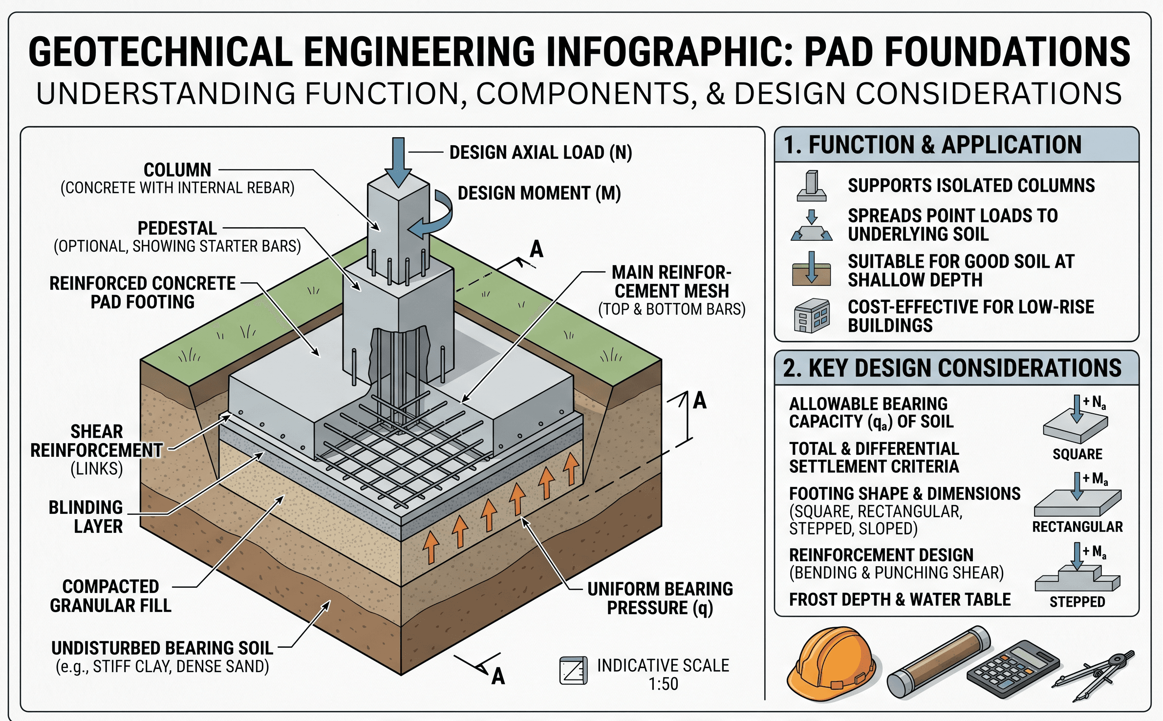
Start by noticing the relationship between column load, footing plan area, embedment depth, and soil reaction. That simple load-spreading concept is what makes pad foundations work, but real design still depends on eccentricity, settlement, groundwater, and how uniform the supporting stratum actually is.
What is a pad foundation?
A pad foundation, often called an isolated footing, is a discrete shallow foundation placed below an individual column, pier, or concentrated support point. Its job is straightforward: increase the contact area between the structure and the ground so the resulting stress on the soil stays within acceptable design limits.
In practice, the reason engineers like pad foundations is efficiency. If the loads are moderate, the column spacing is not too tight, and the near-surface soils are reasonably competent, a separate footing under each column is often the most economical and easiest-to-build solution. The geometry is simple, excavation is localized, reinforcement detailing is usually manageable, and construction crews are familiar with the sequence.
That said, a pad foundation is never just a concrete block under a column. Geotechnically, it is a stress-transfer problem. Structurally, it is a reinforced element resisting bending, shear, and often punching. From a project perspective, it is also a settlement-control decision. A footing can appear adequate on paper yet still create serviceability issues if adjacent pads move differently, if one bears on a softer pocket, or if drainage changes the supporting soil after construction.
A useful way to think about pad foundations is this: they are the most common shallow foundation choice when the load path is discrete and the ground conditions are good enough that deep foundations or large combined systems are unnecessary.
Core principles, variables, and units
Pad foundation performance is governed by a small group of core variables: applied load, footing size, embedment depth, soil strength, and expected movement. These variables interact. Increasing footing area reduces average contact pressure, but it may increase excavation, self-weight, and reinforcement demands. Deeper embedment may improve confinement and help with frost or erosion protection, but it can also increase groundwater and construction complexity.
Key variables and typical ranges
The exact numbers depend on project type and soil profile, but the most useful design habit is range-checking every input before accepting a result. One suspicious value, such as an unrealistically high allowable pressure or ignored moment eccentricity, can make the entire footing look safer than it really is.
- P Vertical column load, usually in kN, kip, or kips. May represent service load, factored load, or both depending on the design method.
- A Footing plan area, commonly in m² or ft². A first-pass sizing variable that strongly influences contact pressure.
- q Average soil contact pressure at the base, usually in kPa, psf, or ksf. This must be checked against the project’s design support criterion.
- qallow Allowable bearing pressure or equivalent service-level geotechnical support value used for preliminary footing sizing.
- B, L Footing width and length. These control area, structural action, eccentricity effects, and plan coordination with nearby footings or property lines.
- Df Embedment depth from finished grade to footing base. Important for confinement, frost depth, erosion exposure, and adjacent excavation effects.
- e Eccentricity of the resultant load. Even modest eccentricity can make base pressure nonuniform and reduce the effective footing area.
- s Estimated settlement. Total settlement matters, but differential settlement between neighboring supports often controls serviceability.
Treat any single “allowable soil pressure” value as the start of the conversation, not the end. Ask what load condition, settlement tolerance, footing width, and groundwater assumption that number actually depends on.
Decision logic and design workflow
Pad foundation design is best approached as a sequence of filters rather than one equation. The footing only remains a good option if it keeps passing those filters as the design becomes more realistic.
Start with the structural support pattern. If the structure is column-supported and individual loads are reasonably separated, a pad is a candidate. Next, review the geotechnical profile: are near-surface soils strong and consistent enough for shallow support? Then perform a first-pass area check using service loads and the project geotechnical bearing criterion. After that, review eccentricity, uplift, lateral effects if relevant, settlement, footing overlap, groundwater, frost/scour exposure, and construction access. If the footing becomes too large, too deep, or too sensitive to movement, compare alternatives such as strip foundations, rafts, ground improvement, or piles.
The most common failure in early foundation layout is stopping too soon. Many preliminary pads look reasonable until the column moments, property-line constraints, adjacent footings, or settlement differentials are added. At that point, the design choice may change even though the simple average-pressure check still appears acceptable.
Equations and calculations
For preliminary geotechnical sizing, the most common first step is to relate the applied service load to an allowable support pressure. This does not complete the design, but it gives a practical starting area.
Here, \(A_{req}\) is the required footing area, \(P\) is the service-level vertical load used for geotechnical sizing, and \(q_{allow}\) is the allowable soil bearing pressure or equivalent allowable support value from the geotechnical basis of design. Once a trial footing size is chosen, the average contact pressure is commonly checked as:
When the column load is eccentric because of applied moments or geometry constraints, pressure is no longer uniform. A simplified one-direction pressure expression is often written as:
where \(M\) is the applied moment and \(S\) is the footing section modulus for the pressure-distribution check. In practice, the exact treatment depends on whether eccentricity acts in one direction or two, whether uplift occurs at an edge, and which structural and geotechnical design methodology the project uses.
Engineers also keep the “effective area” idea in mind. If eccentricity becomes too large, part of the footing may effectively unload, which means the actual bearing area shrinks and the remaining compression zone carries higher pressures. That is why pads near property lines, with large overturning moments, or with misaligned columns often become less efficient than they first appear.
Worked example
Example
Suppose a column delivers a service vertical load of 900 kN to a shallow footing, and the geotechnical recommendation allows a service bearing pressure of 180 kPa for the founding level under the anticipated settlement tolerance. A first-pass required area is:
A square trial footing would therefore be about \( \sqrt{5.0} \approx 2.24 \text{ m} \) on each side. If the engineer rounds to a 2.3 m by 2.3 m footing, the average contact pressure becomes:
At first glance, that looks acceptable because the average pressure is below the recommended 180 kPa. But the design is not finished. The engineer still needs to ask: Is there significant moment from the column? Is the footing close to another footing or a property line? What settlement is expected from the actual stratigraphy? Does groundwater soften the bearing layer? Is the base elevation low enough to avoid erosion, frost, or future utility disturbance? And on the structural side, is the thickness adequate for bending, one-way shear, and punching?
That is exactly why pad foundations are often easy to size roughly but harder to finalize correctly. The first-pass area check gets you into the right neighborhood. The surrounding checks determine whether the footing truly belongs there.
Engineering judgment and field reality
Field performance depends on soil uniformity much more than many simplified classroom examples suggest. Two pad foundations carrying similar loads can behave very differently if one bears on compact sandy soil and the other lands on a soft pocket, utility trench backfill, desiccated crust over soft clay, or weathered zone with variable moisture.
Construction sequence also matters. A footing designed for “competent native soil” can lose that advantage if the excavation sits open in rain, if the subgrade is remolded by traffic, or if crews overexcavate and backfill loosely without the required compaction control. Groundwater often turns a manageable shallow footing into a more complicated system because softening, pumping difficulty, and base disturbance become practical risks, not just theoretical ones.
Experienced engineers therefore do not rely only on a calculated footing area. They review the founding stratum description, excavation stability, need for proof-rolling or base inspection, potential undercut quantities, and whether the geotechnical recommendation should include a construction observation requirement. Pads are simple to draw, but they are unforgiving when the base condition is misread.
A footing founded on “the same layer” is not automatically founded on the same quality of material. Changes in moisture, density, disturbance, or old trench backfill can create differential performance even across a short distance.
When this breaks down
Pad foundations stop being the best answer when one or more of their core assumptions no longer hold. The first major warning sign is weak or compressible near-surface soil. If the founding layer cannot provide adequate support without large footing areas or excessive settlement, a pad may still be technically possible but no longer practical.
A second warning sign is overlap. When neighboring pad foundations grow so large that they begin to touch or leave only narrow strips of soil between them, the system starts behaving more like a combined footing or raft. At that stage, treating each support independently can hide system-level settlement and stiffness behavior.
A third limitation is large eccentricity or constrained geometry. Pads at property lines, near basements, adjacent to existing foundations, or under highly moment-loaded columns may develop strongly nonuniform contact stresses. The footing then becomes inefficient, and the “simple pad” assumption starts to break down.
Finally, deep compressible strata can defeat an otherwise adequate shallow bearing layer. A surface sand may provide acceptable near-term support, but if a thick soft clay layer below it controls long-term settlement, a pad foundation may no longer meet serviceability requirements even though bearing capacity appears acceptable.
Common pitfalls and engineering checks
- Using a geotechnical bearing value without checking the settlement condition behind it.
- Ignoring column moments, eccentricity, or uplift zones in the base pressure distribution.
- Assuming all pads on a site will behave the same despite variable fill, moisture, or soft pockets.
- Overlooking footing overlap or the transition point where a raft or combined footing is more rational.
- Forgetting that structural thickness, punching shear, and reinforcement may govern even when geotechnical sizing seems moderate.
- Neglecting groundwater, excavation instability, or the need for subgrade protection during construction.
One of the costliest mistakes is treating footing design as a bearing-capacity-only problem. Many pad foundation issues show up later as differential settlement, edge overstress from eccentricity, or construction-driven subgrade damage rather than classic bearing failure.
Before finalizing a pad foundation layout, ask three plain questions: Are the footings still independent in behavior? Is serviceability more critical than ultimate capacity here? And would field conditions let the contractor actually build the footing on the soil model you assumed?
| Parameter | Symbol | Typical units | Why it matters |
|---|---|---|---|
| Vertical load | P | kN, kip | Primary input for area sizing and structural demand. |
| Allowable support value | qallow | kPa, psf, ksf | Connects the footing size to geotechnical recommendations. |
| Footing width/length | B, L | m, ft | Control area, pressure, overlap, and practical layout. |
| Embedment depth | Df | m, ft | Affects founding conditions, confinement, frost, and erosion exposure. |
| Eccentricity | e | m, in, ft | Can make contact pressure nonuniform and reduce effective area. |
| Settlement | s | mm, in | Often the actual performance limit for buildings and frames. |
Visualizing pad foundations in a real layout
The most useful mental picture is not one footing by itself but an entire column grid. Imagine a framed structure with isolated supports at regular spacing. If each footing remains modest in plan size and the soil conditions are fairly consistent, separate pads make sense. As loads increase, property-line constraints tighten, or compressible ground demands larger bases, the pads start growing toward each other. That visual transition is often the clearest signal that the project may be drifting toward combined footings or a raft foundation.
This is also why layout review matters early. A foundation type can become inefficient long before it becomes impossible.
Relevant standards and design references
Pad foundations sit at the intersection of structural detailing, geotechnical interpretation, and construction quality. The exact governing references depend on project type and location, but these are the documents engineers commonly coordinate around:
- IBC and local building code requirements: Establish the overall framework for foundation design, loading, frost depth, and code compliance.
- ACI 318: Governs reinforced concrete footing design, including flexure, one-way shear, punching shear, detailing, and development requirements.
- Project geotechnical report: Usually the direct source for allowable bearing values, settlement expectations, groundwater observations, founding elevations, and undercut or proof-roll recommendations.
- ASTM and AASHTO soil test standards: Provide the basis for classification, strength, density, and compressibility data used to justify the design parameters in the geotechnical recommendations.
- Agency or owner foundation criteria: May define tolerable settlement, minimum embedment, inspection requirements, or resistance-factor methods that alter how pad foundations are finalized.
Frequently asked questions
A pad foundation supports one column or concentrated load at a discrete location, while a strip foundation runs continuously under a wall or line load. Pads are common for framed buildings with isolated columns, whereas strips are better suited to load-bearing wall systems and other continuous support conditions.
Ultimate bearing capacity is important, but serviceability often controls in real projects. Settlement, eccentric loading, footing overlap, groundwater, and construction quality can govern whether a pad foundation actually performs well even when the average bearing pressure looks acceptable.
They become less attractive when near-surface soils are weak or compressible, when the footings grow large enough to overlap, when eccentricity becomes significant, or when deep compressible layers drive settlement. At that point, engineers often compare strip, raft, improved-ground, or pile-supported solutions.
Pad foundations are widely used below individual steel or concrete columns in buildings, industrial frames, utility structures, equipment supports, and other projects with discrete point loads. They are especially common where shallow competent material is available close to grade and a separate footing under each support remains buildable and economical.
Summary and next steps
Pad foundations are one of the most common shallow foundation systems because they solve a very common structural condition: a single column load that needs to be spread safely into the ground. Their apparent simplicity is exactly why they are often underestimated. Good design requires more than a quick area calculation. It requires understanding the soil profile, likely settlement behavior, eccentricity, groundwater, construction sequence, and when neighboring footings stop behaving independently.
In many projects, the real design control is not catastrophic bearing failure but serviceability and buildability. The best pad foundation designs are proportioned with clear load paths, realistic geotechnical assumptions, practical excavation expectations, and enough judgment to know when another foundation type should be considered instead.
Where to go next
Continue your learning path with these curated next steps.
-
Read a deeper dive on foundation design
Useful for seeing how geotechnical and structural footing decisions fit into the wider foundation selection process.
-
Study settlement analysis next
A strong follow-on topic because footing performance is often controlled by movement, not just by ultimate support pressure.
-
Compare with pile foundations
Helpful when shallow soils become unreliable and a deeper support strategy starts to make more sense.