Key Takeaways
- Definition: Wind design turns site wind hazard, exposure, geometry, and pressure effects into structural and cladding design demands.
- Use case: Engineers use wind design to size lateral systems, roof attachments, wall cladding, diaphragms, connections, and foundations.
- Main decision: The key task is separating overall building wind effects from localized component and cladding pressures.
- Outcome: A good design provides strength, stability, water-tightness, drift control, uplift resistance, and a continuous load path.
Table of Contents
Introduction
In brief: Wind design estimates wind pressures and checks the structure, cladding, connections, and foundations that transfer wind safely to the ground.
Who it’s for: Students and early-career designers.
For informational purposes only. See Terms and Conditions.
Wind design matters because wind rarely acts as one simple force. It creates suction, pressure, uplift, torsion, drift, vibration, and localized demands that must move through a complete structural load path.
Wind design infographic
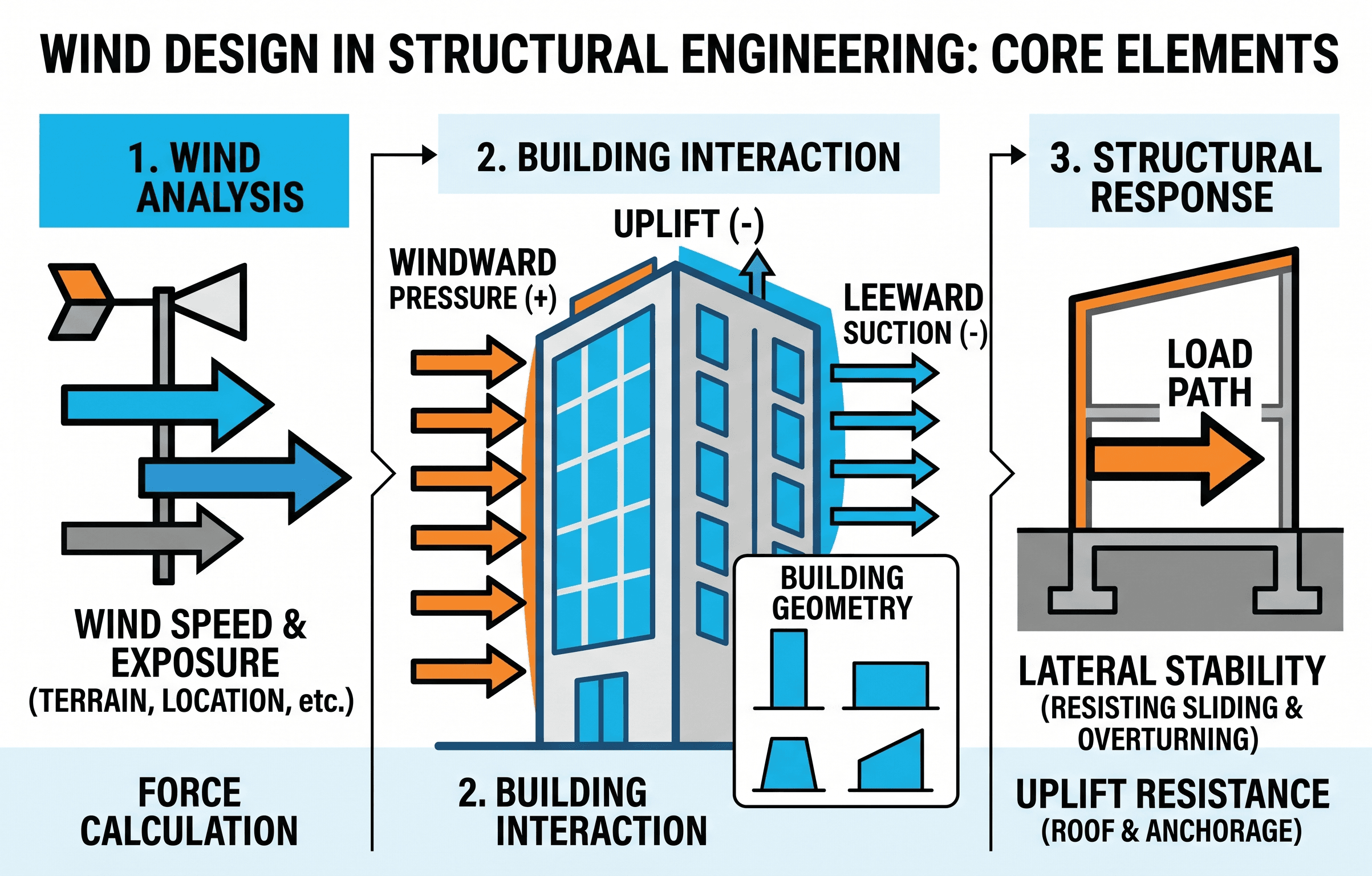
Notice that wind does not stop at the exterior surface. Pressure on a wall or suction on a roof must be resisted locally by fasteners and panels, then globally by the building’s lateral system and foundation.
What is wind design?
Wind design is the structural engineering process used to estimate wind pressures on a building or structure and design every affected element to resist those forces safely. It includes the main structural system, exterior cladding, roof attachments, diaphragms, connections, anchors, foundations, and sometimes occupant comfort.
In simple terms, wind design answers four questions: how strong can the wind be at this site, how does the building shape change that wind into pressure and suction, which parts of the structure receive the load, and how does the load reach the ground without failure or excessive movement?
Wind is especially important because it can control both strength and serviceability. A beam may be sized by gravity load, but a wall panel, roof deck, anchor bolt, shear wall, braced frame, moment frame, or tall building core may be controlled by wind effects. For a broader starting point, review structural loads and load path analysis.
Wind design is not only a pressure calculation. It is a system check that connects hazard, exposure, geometry, pressure zones, load combinations, lateral stiffness, cladding resistance, and foundation stability.
How wind loads move through a structure
A reliable wind design starts with the load path. Wind pressure first acts on surfaces: roof zones, wall zones, parapets, canopies, rooftop equipment, screens, doors, windows, and cladding panels. Those surface loads then move through local attachments before entering the primary structural system.
For a wall, wind may travel from cladding to girts or studs, from girts to columns or frames, from frames into the diaphragm or lateral system, and finally into the foundation. For a roof, uplift may travel from membrane or roof panels to fasteners, deck, joists, beams, diaphragms, vertical resisting elements, anchors, and foundations.
This is why wind failures often occur at connections or enclosure components before a main frame collapses. A building can have strong columns and beams while still losing roof panels, wall panels, glazing, rooftop equipment, or garage doors if local wind pressures and attachments are underestimated.
Many wind-related losses are envelope and connection problems, not dramatic frame failures. Check the small pieces: edge zones, corner zones, anchors, clips, fasteners, blocking, and attachment spacing.
MWFRS vs. components and cladding
A key wind design distinction is the difference between the main wind force resisting system, often abbreviated MWFRS, and components and cladding, often abbreviated C&C. These two design tracks answer different questions and should not be mixed casually.
The MWFRS carries the overall building wind effects. It is concerned with base shear, overturning, story forces, diaphragm forces, torsion, drift, sliding, uplift, and the global stability of the building. Braced frames, moment frames, shear walls, diaphragms, collectors, chords, foundations, and anchorage usually belong to this system-level check.
Components and cladding checks focus on local surface pressures. These checks apply to roof zones, wall zones, windows, doors, exterior panels, roof deck, purlins, girts, curtain wall anchors, fasteners, and similar elements. Local pressures can be much higher than average building pressures because of flow separation, suction at corners, roof edges, and localized turbulence.
| Design track | Main question | Typical elements | Common controlling issue |
|---|---|---|---|
| MWFRS | Can the building resist overall wind forces? | Frames, walls, diaphragms, collectors, foundations | Drift, overturning, base shear, torsion, anchorage |
| Components and cladding | Can local exterior elements resist peak pressures? | Roof panels, wall panels, windows, doors, fasteners | Roof uplift, panel pull-off, broken glazing, fastener failure |
| Attachments and equipment | Can mounted elements stay connected? | Signs, screens, solar arrays, rooftop units, canopies | Anchorage, uplift, vibration, load transfer into supports |
Do not use a low average MWFRS pressure to design a roof edge clip, window anchor, or wall panel fastener. Local component pressures can control those details.
Core wind pressure equation and variables
Most building wind procedures begin with velocity pressure. The exact code procedure depends on the adopted standard, building type, risk category, exposure, height, enclosure classification, directionality, topography, and pressure coefficients. The core idea is that wind pressure increases with the square of wind speed.
In this common U.S. customary form, \(q_z\) is velocity pressure in pounds per square foot when \(V\) is wind speed in miles per hour. The coefficients adjust the basic wind speed for height, exposure, topographic effects, and directionality. Project-specific code requirements may include additional factors or different notation.
- \(q_z\) Velocity pressure at height \(z\), commonly expressed in psf in U.S. customary design.
- \(V\) Basic design wind speed, typically taken from adopted wind speed maps for the project location and risk category.
- \(K_z\) Exposure coefficient accounting for height above ground and terrain roughness.
- \(K_{zt}\) Topographic factor used when hills, ridges, or escarpments can accelerate wind flow.
- \(K_d\) Wind directionality factor reflecting the probability of maximum wind effects occurring from the most critical direction.
After velocity pressure is determined, the engineer applies pressure coefficients to convert wind speed into design pressure on the surface or system being checked. External pressure coefficients, internal pressure coefficients, gust effects, and net pressure zones are what turn a general wind hazard into specific design demands.
Because pressure varies with \(V^2\), a modest increase in design wind speed can create a much larger increase in design pressure. Always check wind speed units, maps, risk category, and exposure before trusting the result.
Wind design workflow
The wind design workflow should move from site hazard to surface pressures to load path checks. Jumping directly into member sizing without classifying the building and pressure zones can miss the demands that actually control.
Define site and risk category → determine design wind speed → select exposure and topographic factors → classify enclosure → identify MWFRS and C&C elements → calculate pressures → apply load combinations → check strength, drift, uplift, sliding, overturning, anchorage, and serviceability.
1. Establish the wind hazard
Start with the adopted building code and wind speed map for the project location. Confirm the risk category because hospitals, emergency facilities, schools, storage buildings, standard commercial buildings, and low-risk structures may not use the same wind reliability target.
2. Classify exposure and site effects
Terrain affects wind speed near the ground. Open water, flat open terrain, suburban areas, wooded areas, dense urban areas, escarpments, hills, and ridges can produce different pressure demands. Exposure is not a paperwork item; it can materially change the design.
3. Separate global and local checks
Identify the MWFRS for the overall building and the C&C elements for local pressure checks. The same wall line may participate in both tracks: the frame or shear wall resists global lateral force, while the cladding and anchors resist local suction and pressure.
4. Verify the load path
Trace roof uplift, wall pressure, diaphragm shear, chord force, collector force, overturning tension, compression reactions, sliding resistance, and foundation anchorage. If a force cannot be traced, the design is not complete.
What controls wind design?
Wind design is often controlled by the part of the structure with the least tolerance for pressure, suction, movement, or connection demand. For a low-rise warehouse, roof uplift and wall panel attachment may control. For a tall building, drift and acceleration may control. For a rooftop solar array, anchorage and load transfer into the roof structure may control.
The controlling check may also change by location on the same building. Roof corners often see different local pressures than interior roof zones. Windward walls, leeward walls, side walls, parapets, overhangs, canopies, and openings may each require separate consideration.
| Project condition | Likely control | What to check carefully |
|---|---|---|
| Low-rise metal building | Roof uplift and wall cladding | Fastener spacing, purlins, girts, end bays, corners, doors |
| Tall building | Drift, acceleration, overturning, torsion | Core stiffness, outrigger behavior, comfort limits, P-delta effects |
| Building with large openings | Internal pressure | Enclosure classification, dominant openings, garage doors, glazing |
| Rooftop equipment or solar | Attachment and load transfer | Anchors, rails, ballast, deck capacity, waterproofing, uplift paths |
| Canopy or overhang | Net uplift and local suction | Top and bottom pressures, framing continuity, connection prying |
Ask what would fail first if the wind load were increased: cladding, fasteners, roof deck, diaphragm, collector, frame, foundation anchor, or serviceability limit. That answer often reveals the controlling design issue.
Worked example: roof uplift and lateral load path
Example scenario
Consider a one-story commercial building in an open exposure with metal roof deck, steel joists, perimeter frames, and large overhead doors. The building is not tall, so occupant acceleration is not the main concern. The likely wind concerns are roof uplift, wall cladding, diaphragm shear, frame reactions, and foundation anchorage.
Step 1: Identify design tracks
The roof deck, roof fasteners, edge zones, wall panels, doors, and exterior attachments are checked as components and cladding. The steel frames, roof diaphragm, collectors, base plates, anchor rods, and foundations are checked as the MWFRS load path.
Step 2: Estimate surface pressure
Suppose the applicable net uplift pressure for a roof zone is 35 psf. A roof panel tributary area of 20 square feet would have an unfactored uplift demand of:
That 700 lb demand does not disappear at the panel. It must be resisted by the panel, fasteners, supporting deck or purlin, connection to joists or frames, and the structural elements that keep the roof attached to the building.
Step 3: Trace the force into the structure
If the roof diaphragm also transfers lateral wind shear to frames, the engineer must verify deck fastening, diaphragm capacity, chord forces, collector connections, frame design, base reactions, anchor rods, and foundation resistance. A local roof uplift check and a global frame check are separate but connected.
The pressure number is only the beginning. A complete wind design turns that pressure into panel forces, connection forces, diaphragm forces, frame forces, and foundation forces.
Engineering judgment and field reality
Wind design looks clean in equations, but field performance depends heavily on detailing and construction. A correct wind speed and pressure calculation will not save a building if the roof edge is poorly fastened, the diaphragm boundary is discontinuous, the collector is interrupted, or the anchor bolts are not installed as assumed.
Openings deserve special attention. A failed garage door, broken window, damaged louver, or missing wall panel can change internal pressure and create demands that were not intended for the original enclosure classification. In hurricane-prone and high-wind regions, enclosure assumptions must match the actual construction and expected protection of openings.
Wind design also requires coordination between disciplines. Architects select cladding and roof shapes. Mechanical engineers place rooftop equipment. Solar contractors add arrays. Owners request signs, screens, and canopies. Each addition can change wind loads or create new attachment demands.
Wind failures often start where drawings are least coordinated: roof edges, parapets, equipment curbs, expansion joints, canopy connections, wall penetrations, and post-installed attachments.
When this breaks down
Simplified wind design procedures break down when the structure does not behave like the assumptions behind the method. Unusual shapes, very flexible structures, complex roofs, open structures, long-span roofs, tall slender buildings, and buildings with important aerodynamic effects may require more advanced analysis.
Wind tunnel testing or specialized wind engineering may be appropriate when building shape, surroundings, height, flexibility, occupant comfort, or cladding sensitivity make standard assumptions too approximate. Tall buildings, stadium roofs, long-span canopies, slender towers, bridges, and unusual façade systems can all fall into this category.
The method can also break down when the site classification is wrong. A building near open water, a ridge, a large flat approach, or a rapidly changing terrain condition may experience wind effects that differ from a casual exposure assumption.
- Unusual geometry that causes complex flow separation or pressure zones.
- Flexible structures where dynamic response matters.
- Large openings or enclosure uncertainty that affects internal pressure.
- Rooftop equipment, screens, signs, or solar arrays added after original design.
- Structures near hills, escarpments, coastlines, or open terrain transitions.
- Cladding systems with limited test data or unclear attachment capacity.
Common pitfalls and engineering checks
Wind design mistakes usually come from assumptions, not arithmetic. A pressure calculation can be numerically correct while still being applied to the wrong element, wrong zone, wrong tributary area, wrong enclosure classification, or incomplete load path.
- Using MWFRS pressures for components and cladding elements.
- Ignoring roof edge and corner zones where uplift can be higher.
- Assuming an enclosed building when large openings or weak doors may control.
- Forgetting uplift load paths through joists, seats, deck, anchors, and foundations.
- Checking member strength but not drift, acceleration, cladding movement, or water-tightness.
- Using default software settings without verifying exposure, coefficients, and load combinations.
- Missing added rooftop equipment, solar arrays, screens, signs, and canopies.
The most dangerous wind design assumption is that the main frame check proves the building is wind-resistant. Exterior components, connections, and discontinuities can fail first.
| Check | Question to ask | Why it matters |
|---|---|---|
| Exposure | Does terrain match the selected exposure? | Exposure strongly affects velocity pressure with height. |
| Pressure zones | Are edges, corners, and interior zones separated? | Local suction often controls cladding and fasteners. |
| Enclosure | Can openings change internal pressure? | Internal pressure can significantly increase net roof and wall demands. |
| Load path | Can each wind force be traced to the ground? | Missing collectors or anchors can create brittle weak links. |
| Serviceability | Are drift, movement, and cladding compatibility acceptable? | Strength alone does not prevent façade damage or user discomfort. |
Visualizing wind design as a system
A useful way to visualize wind design is to split the building into three layers: the exterior surface layer, the collector and diaphragm layer, and the primary resisting layer. The exterior surface receives pressure and suction. The collector and diaphragm layer gathers those forces. The primary resisting layer transfers them into foundations and soil.
This system view prevents over-focusing on one member. A roof deck fastener, diaphragm chord, shear wall hold-down, base plate anchor, or footing may be just as important as the frame member that appears most obvious in a structural model.
Use this mental model during design review: surface pressure, local attachment, collector path, lateral system, foundation resistance.
Relevant standards and design references
Wind design is governed by the adopted building code and its referenced standards. Always verify the project jurisdiction, adopted code edition, local amendments, occupancy risk category, and owner-specific criteria before final design.
- ASCE/SEI 7: The primary U.S. reference for minimum design loads, including wind speed maps, exposure, velocity pressure, MWFRS procedures, components and cladding pressures, and load combinations.
- International Building Code: The model building code commonly used to establish structural design requirements and point designers to referenced standards such as ASCE/SEI 7.
- Material design standards: Standards such as AISC 360, ACI 318, TMS 402, and the National Design Specification for Wood Construction are used after wind effects are converted into member, connection, and anchorage demands.
- Product approvals and tested assemblies: Cladding, roof systems, doors, windows, anchors, and rooftop equipment attachments often require tested capacities or approved installation criteria for the project wind pressures.
- Local amendments and coastal requirements: High-wind, hurricane-prone, tornado-prone, and coastal regions may have additional requirements for openings, debris impact, roof attachments, essential facilities, or resilience.
Frequently asked questions
Wind design is the process of estimating wind pressures and designing the structure, cladding, connections, diaphragms, lateral system, and foundations to safely resist those pressures without excessive damage or movement.
The controlling issue depends on the structure, but common controls include cladding pressures, roof uplift, lateral drift, overturning, torsion, connection forces, diaphragm transfer, and serviceability limits.
The MWFRS carries overall building wind effects such as base shear, overturning, and drift, while components and cladding checks focus on localized pressures on roof panels, wall cladding, fasteners, windows, doors, and attachments.
Roof corners and edges are important because wind flow separates around building edges and can create high localized suction. These zones often control roof deck, membrane, panel, and fastener design.
Simplified wind design becomes unreliable for unusual geometry, flexible structures, open buildings, tall or slender buildings, complex roof shapes, exposed sites, and cases where torsion, vibration, or wind tunnel effects may govern.
Summary and next steps
Wind design is the structural process of converting site wind hazard into pressures, forces, movements, and connection demands. It includes both the main wind force resisting system and the local components and cladding that receive peak pressures on walls, roofs, openings, and attachments.
The most important idea is continuity. Wind must move from the exterior surface through fasteners, panels, framing, diaphragms, collectors, vertical resisting elements, anchors, foundations, and soil. A design is not complete until that full path is clear and each link has adequate strength and serviceability.
In practice, good wind design requires more than equations. It requires site judgment, exposure checks, pressure zone awareness, coordination with architecture and mechanical systems, realistic enclosure assumptions, and careful detailing at edges, corners, anchors, openings, and roof attachments.
Where to go next
Continue your learning path with these curated structural engineering topics.
-
Study structural loads
Learn how wind, dead, live, seismic, snow, rain, and other loads are classified before structural design begins.
-
Review load path analysis
Deepen the key concept behind wind design: how forces move through connected elements into foundations and soil.
-
Explore structural dynamics
Useful for understanding vibration, resonance, acceleration, and dynamic response in wind-sensitive structures.