Key Takeaways
- Definition: Timber design sizes wood members and connections so structures safely resist loads while controlling deflection, moisture effects, and long-term performance.
- Use case: It is used for beams, joists, columns, trusses, shear walls, diaphragms, decks, glulam, CLT, and mass timber systems.
- Main decision: The designer must balance strength, serviceability, connection detailing, grain direction, load duration, moisture exposure, fire, and constructability.
- Outcome: Good timber design produces a clear load path with practical member sizes, reliable connections, and details that work in real field conditions.
Table of Contents
Introduction
In brief: Timber design uses wood properties, load paths, adjustment factors, and connection checks to create safe, serviceable structural systems.
Who it’s for: Students and early-career designers.
For informational purposes only. See Terms and Conditions.
Timber design is not just picking a beam from a span table. It is a coordinated design process that connects wood behavior, structural loads, member sizing, connections, moisture, fire, and construction details.
Timber design infographic
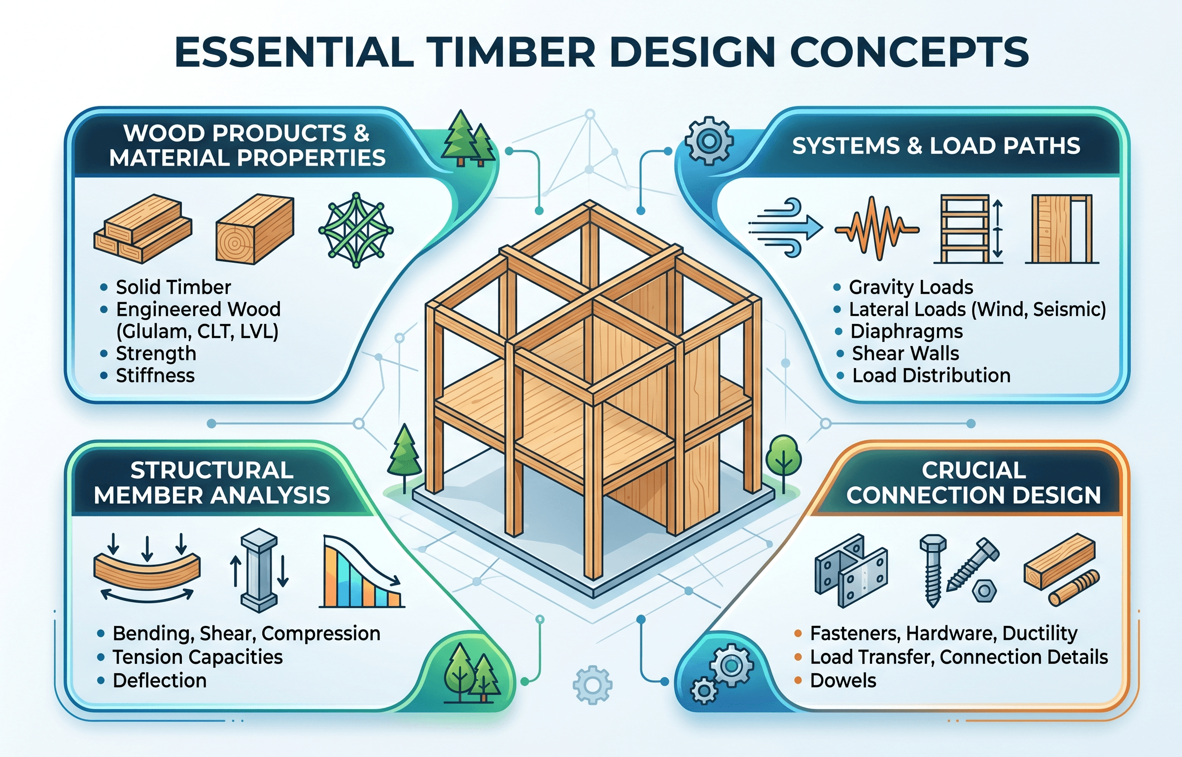
Notice that timber design is controlled by more than bending strength. Grain direction, connection layout, moisture conditions, load duration, bearing, deflection, vibration, and detailing can all govern the final design.
What is timber design?
Timber design is the structural engineering process of proportioning wood members and their connections so a building, bridge, roof, platform, or frame can resist applied loads safely over its service life. The process includes selecting member types, determining design loads, analyzing force effects, applying wood design adjustment factors, checking strength and serviceability, detailing connections, and accounting for environmental exposure.
Wood is different from steel and concrete because it is naturally variable, direction-dependent, and sensitive to moisture. A member can be strong parallel to grain but weak perpendicular to grain. A connection can have adequate fastener capacity but still split the member if edge distance, end distance, spacing, or installation sequence is wrong. A beam can pass a bending check but fail a deflection, vibration, bearing, or creep check.
In structural engineering, timber design applies to sawn lumber, glued-laminated timber, structural composite lumber, I-joists, wood panels, poles, piles, cross-laminated timber, diaphragms, shear walls, trusses, and hybrid wood-steel or wood-concrete systems. The exact design method depends on the adopted building code, the product standard, the project loading criteria, and the structural system.
Before sizing members, trace the load path from roof or floor sheathing into joists, beams, columns, walls, diaphragms, foundations, and lateral-force-resisting elements.
How timber behaves structurally
Timber is an anisotropic material, meaning its strength and stiffness depend on direction. Properties parallel to the grain are very different from properties perpendicular to the grain. This is why a timber beam may carry large bending forces along its length, but bearing perpendicular to grain at supports may become a controlling limit state.
Grain direction matters
Most primary member checks are tied to how stress aligns with the grain. Tension parallel to grain, compression parallel to grain, bending about the strong axis, horizontal shear, and compression perpendicular to grain each behave differently. Connection details must also respect grain direction because splitting often occurs along the grain rather than through a uniform material block.
Wood is variable by grade and product
Timber design uses assigned design values based on species, grade, product type, moisture condition, size, load duration, and other adjustment factors. A visually graded sawn member, a machine-stress-rated member, a glulam beam, a laminated veneer lumber beam, and a CLT panel are not interchangeable unless the design values and product limitations are verified.
Moisture changes the design problem
Moisture affects strength, stiffness, durability, dimensional stability, connection performance, and long-term serviceability. Members installed wet, exposed to intermittent wetting, or trapped in poorly ventilated assemblies can shrink, swell, check, decay, or lose connection reliability. Timber design therefore includes both structural checks and detailing choices that keep the member dry enough for the intended service condition.
Many timber problems begin as detailing problems: trapped water, missing flashing, fasteners too close to member ends, unprotected end grain, or connection hardware that does not match the assumed load path.
Core principles, variables, and units
Timber design compares demand from structural analysis against adjusted resistance values for the specific member, product, orientation, and service condition. For a beam, the engineer may check bending, shear, bearing, deflection, vibration, lateral stability, notching, holes, and connection transfer. For a column, compression strength, slenderness, bracing, bearing, and connection eccentricity may control.
Key variables and typical checks
The following variables appear often in timber design. Exact values depend on the design standard, product data, adopted code, and project-specific assumptions.
- \( F_b \) Reference bending design value, commonly expressed in psi or MPa before applicable adjustment factors.
- \( F_v \) Reference shear design value used for beam shear checks and adjusted for applicable conditions.
- \( E \) Modulus of elasticity, used for deflection, vibration, and stability checks.
- \( M \) Bending moment demand from the structural analysis model or hand calculation.
- \( V \) Shear demand near supports, concentrated loads, notches, or connection transfer points.
- \( \Delta \) Deflection under live, dead, or total load combinations, usually compared with span-based limits.
| Design issue | Common check | Why it matters | Field-sensitive detail |
|---|---|---|---|
| Bending | Moment demand versus adjusted bending capacity | Controls beam depth, grade, and product selection | Unbraced compression edge and lateral restraint |
| Shear | Shear demand near supports and concentrated loads | Can control short-span deep members | Notches, holes, and end checks |
| Bearing | Compression perpendicular to grain at supports | Prevents crushing, settlement, and rotation | Seat length, plates, washers, and support alignment |
| Deflection | Live-load and total-load deflection limits | Protects finishes, partitions, drainage, and perception | Creep, moisture, camber, and construction tolerances |
| Connections | Fastener, bearing, spacing, group action, and splitting checks | Often controls real structural performance | Edge distance, end distance, installation quality |
Do not stop after the first bending check. In timber design, deflection, bearing perpendicular to grain, lateral restraint, or connection detailing often controls the final member size.
Timber design workflow
A practical timber design workflow starts with the structural system, then moves into member checks and connection detailing. This order matters because wood members rarely behave well when connections are designed after the layout is already fixed.
Step 1: define the structural system
The system decision determines how loads travel through the structure. A light-frame building may rely on sheathed diaphragms, shear walls, joists, headers, studs, and hold-downs. A heavy timber or mass timber building may use glulam beams and columns, CLT floor panels, proprietary connectors, steel drag elements, concrete cores, or hybrid lateral systems. The member design should match the actual load path rather than isolated span assumptions.
Step 2: determine loads and combinations
Timber members must resist dead load, live load, roof live load, snow, wind, seismic effects, rain, construction loads, vibration-sensitive occupancies, and sometimes equipment or storage loads. Long-duration loads and short-duration loads may be treated differently depending on the design method, so the load case can affect both demand and allowable resistance.
Step 3: select member type and preliminary size
Preliminary sizing may begin with span tables, rules of thumb, previous projects, or structural analysis. However, final sizing requires project-specific checks. A sawn lumber joist may work for short residential spans. Glulam or structural composite lumber may be better for longer spans or higher loads. CLT panels may be selected for floor, roof, or wall behavior when diaphragm action, fire resistance, prefabrication, and exposed wood appearance are part of the project goals.
Step 4: check strength and serviceability
Each member is checked for the limit states that match its behavior. Beams are commonly checked for bending, shear, bearing, deflection, vibration, lateral stability, and modifications such as holes or notches. Columns are checked for compression, slenderness, bracing, bearing, and eccentric loading. Panels may require bending, rolling shear, diaphragm transfer, vibration, fire, and connection checks.
Step 5: detail the connections early
Timber connections deserve early attention because they influence member width, support geometry, constructability, shrinkage behavior, tolerance, fire protection, and aesthetics. Bolts, screws, nails, plates, hangers, bearing seats, concealed knife plates, hold-downs, and diaphragm collectors all need enough wood around them to develop the intended force.
Start with load path → choose timber system → select product and grade → check member strength → check deflection and vibration → design bearing and connections → review moisture, fire, shrinkage, and constructability.
Timber design equations and calculations
Timber design equations vary by standard, design method, member type, and product. However, the design logic is consistent: calculate stress or force demand, adjust the reference design value for project conditions, and verify that the adjusted resistance is adequate.
Basic stress check format
A simple allowable-stress-style check compares calculated stress against an adjusted design value:
In this expression, \( f \) is the calculated stress from analysis and \( F’ \) is the adjusted design value after applying relevant factors for load duration, moisture, temperature, size, stability, repetitive use, incising, product type, and other conditions required by the governing design standard.
Bending stress in a rectangular timber member
For a prismatic member with elastic behavior, bending stress is commonly evaluated using:
Here, \( f_b \) is bending stress, \( M \) is the maximum bending moment, and \( S \) is the section modulus. For a rectangular section bent about its strong axis, \( S = bd^2/6 \), where \( b \) is member width and \( d \) is member depth.
Deflection check
For a simply supported beam with uniform load, an initial elastic deflection estimate is:
This equation is useful for understanding the role of span, stiffness, and loading. Because deflection increases with \( L^4 \), a modest span increase can cause a major serviceability problem. Long-term deflection may also increase because of creep and sustained loading.
Using the reference bending value without required adjustment factors can make a member look stronger than it is for the actual service condition.
Timber member types and design decisions
Timber design changes by product because each product has different geometry, grading, manufacturing control, strength direction, and connection behavior. A good design does not only ask “what span can this carry?” It asks whether the selected product fits the load path, exposure, fire rating, vibration target, construction sequence, and connection strategy.
| Product or system | Where it is used | Common controlling checks | Design judgment |
|---|---|---|---|
| Sawn lumber | Joists, rafters, studs, headers, blocking, light-frame systems | Bending, shear, deflection, bearing, fastening | Efficient for repetitive framing but limited by variability and available sizes |
| Glulam | Long-span beams, columns, arches, exposed structural systems | Bending, shear, bearing, stability, connection detailing | Strong option for long spans and architectural exposure when protected and detailed well |
| Structural composite lumber | Headers, beams, rim members, concentrated load paths | Bending, shear, deflection, bearing, proprietary limits | Useful where predictable strength and dimensional stability are needed |
| Wood I-joists | Floor and roof framing | Deflection, vibration, web holes, bearing, fire detailing | Efficient for floor systems but must follow manufacturer limits closely |
| CLT and mass timber panels | Floors, roofs, walls, diaphragms, prefabricated systems | Panel bending, rolling shear, vibration, fire, diaphragm transfer, connections | Best when structure, fire, architecture, erection, and MEP coordination are planned together |
For material-focused background, see timber materials. For system-level framing behavior, continue with timber structures.
Timber connections often control the design
Connections are one of the most important parts of timber design because wood failure near a fastener can be brittle, progressive, or difficult to inspect after finishes are installed. A member may have plenty of bending strength but still perform poorly if loads are transferred through an undersized seat, poorly spaced bolts, overloaded hanger, weak diaphragm boundary, or connection that creates splitting perpendicular to grain.
What connection design must consider
- Fastener type, diameter, penetration, and installation quality.
- Wood species, grade, thickness, and side-member material.
- Load direction relative to grain.
- End distance, edge distance, row spacing, and group action.
- Bearing, tear-out, splitting, net section, and local crushing.
- Shrinkage, moisture movement, tolerance, and construction sequence.
- Fire protection, corrosion resistance, and inspectability.
Light-frame construction often relies on nails, screws, metal connectors, hold-downs, and sheathing attachment patterns. Heavy timber and mass timber systems may use concealed steel plates, self-tapping screws, bearing seats, proprietary connectors, dowels, rods, and hybrid steel-timber details. In all cases, the connection must match the assumed load path.
Review connection eccentricity. A connection that looks adequate in pure shear may introduce torsion, prying, cross-grain tension, or local bearing that was not included in the first calculation.
Engineering judgment and field reality
Timber design depends heavily on field execution. Moisture protection, delivery sequencing, temporary bracing, fastener installation, notching, drilling, bearing fit-up, and tolerance can all affect the structure after the calculations are complete. This is especially important for exposed wood and mass timber projects, where the structure is often both the finish and the load-carrying system.
Moisture and durability
Timber performs well when it is detailed to stay dry or dry out quickly after incidental wetting. Vulnerable locations include end grain, exterior beam pockets, roof penetrations, balcony interfaces, parapets, exposed fasteners, below-grade transitions, and concealed cavities. Good design provides drainage, ventilation, flashing, capillary breaks, corrosion-resistant hardware, and realistic maintenance access.
Serviceability and vibration
Timber floors can be controlled by vibration or perceived flexibility even when strength is adequate. Long spans, low mass, repetitive framing, and open layouts can make vibration noticeable to occupants. Deflection limits should therefore be paired with stiffness, frequency, and comfort expectations when the use is sensitive.
Construction tolerances
Timber is relatively easy to cut in the field, which is both helpful and risky. Uncoordinated holes, notches, trimming, and connection modifications can remove critical section capacity or violate product limitations. Shop drawings, connection coordination, inspection, and clear field repair procedures are part of good timber design.
Exposed timber needs a weather plan before delivery. Temporary wetting during storage or erection can affect appearance, dimensional stability, connection fit-up, and long-term durability.
When this breaks down
Basic timber design guidance breaks down when simple beam, column, or span-table assumptions no longer represent the actual structure. Long-span vibration, unusual connection geometry, heavy concentrated loads, repeated cyclic loading, fire-resistance design, significant moisture exposure, curved members, large openings, diaphragm discontinuities, and mass timber plate behavior may require advanced analysis or product-specific guidance.
The method also breaks down when the design treats wood as if it were a uniform isotropic material. Grain direction, cross-grain tension, shrinkage, creep, checking, product orientation, and fastening geometry can change the governing failure mode. Timber design is usually safest when the engineer checks both the member and the detail that transfers load into the member.
| Condition | Why simple checks may fail | Better design response |
|---|---|---|
| Wet or exterior exposure | Strength, durability, corrosion, and dimensional stability may change | Use correct service condition, protection, drainage, and compatible hardware |
| Long-span floors | Strength may pass while vibration or deflection controls | Evaluate stiffness, frequency, damping, and occupant sensitivity |
| Complex connections | Local splitting, eccentricity, and group effects may govern | Detail load transfer explicitly and verify spacing and geometry |
| Mass timber diaphragms | Panel joints and collectors may control global behavior | Design diaphragm chords, collectors, panel joints, and boundary elements together |
Common pitfalls and engineering checks
Many timber design errors come from treating wood members as isolated elements instead of connected parts of a complete structural system. The following checks help catch common mistakes before they become field issues.
- Check the adopted code edition and the referenced timber design standard before selecting design values.
- Confirm species, grade, product type, and orientation match the structural assumptions.
- Apply load duration, moisture, temperature, size, stability, and other required adjustment factors correctly.
- Verify bearing perpendicular to grain at reactions, posts, seats, and concentrated loads.
- Check deflection, creep, and vibration, especially for long-span floors and roofs.
- Review notches, holes, and field modifications against product and code limitations.
- Detail fastener spacing, edge distance, end distance, corrosion protection, and installation requirements.
- Coordinate fire-resistance rating, encapsulation, char assumptions, and exposed timber appearance.
- Provide moisture protection details at exterior interfaces, roof edges, balconies, and concealed cavities.
Do not assume a deeper timber member automatically solves the problem. A deeper member may still fail bearing, connection, lateral stability, vibration, fire, or shrinkage coordination checks.
Visualizing timber design as a load path
A useful way to visualize timber design is to follow one load through the structure. A roof snow load may move from sheathing into purlins or joists, then into glulam beams, then into columns or walls, then through bearing plates, hold-downs, or foundations. Lateral wind or seismic loads may move through diaphragms, collectors, shear walls, chords, anchors, and foundation elements.
Each transfer point is a design decision. The member must have enough strength and stiffness, but the connection must also deliver the load without splitting the wood, crushing the support, overstressing fasteners, or creating an unintended eccentricity. That is why timber design is most reliable when member sizing and detailing are developed together.
For broader load-path context, review load path analysis and structural loads.
Relevant standards and design references
Timber design should always be checked against the code and standards adopted for the project location. The following references commonly shape U.S. structural wood design.
- International Building Code: Establishes adopted building requirements, references material standards, and connects wood design to occupancy, fire, height, area, and construction type rules.
- ANSI/AWC NDS, National Design Specification for Wood Construction: Provides core design provisions for wood members, adjustment factors, connections, and many structural wood products.
- ASCE 7: Provides minimum design loads and load combinations for gravity, wind, seismic, snow, rain, flood, and other loading conditions used before timber member checks.
- Product standards and manufacturer data: Engineered wood products such as glulam, I-joists, structural composite lumber, and CLT must be checked with applicable product standards, evaluation reports, and manufacturer limits.
- Project specifications and local amendments: Fire rating, preservative treatment, corrosion protection, exposed finish requirements, inspection criteria, and moisture protection are often controlled by project-specific documents.
Frequently asked questions
Timber design is the process of sizing and detailing wood members and connections so beams, joists, columns, walls, diaphragms, and timber systems can safely resist loads while controlling deflection, vibration, moisture effects, fire performance, and long-term durability.
Common controlling checks include bending, shear, bearing perpendicular to grain, column stability, connection capacity, deflection, vibration, moisture exposure, fire design, and constructability. The governing issue depends on span, product type, support condition, load duration, and detailing.
Timber design must account for grain direction, natural variability, moisture sensitivity, load duration, creep, shrinkage, bearing perpendicular to grain, and splitting around fasteners. Steel design is usually more controlled by yielding, buckling, local stability, connection strength, and fabrication tolerances.
Mass timber is a category of timber construction using large engineered wood elements such as CLT panels and glulam members, while timber design is the broader engineering process used for sawn lumber, engineered wood, light-frame systems, heavy timber, and mass timber structures.
Advanced analysis may be needed for long-span vibration, mass timber diaphragms, nonstandard connections, fire-resistance design, heavy concentrated loads, curved glulam members, unusual moisture exposure, progressive load paths, hybrid systems, or structures where simple member checks do not represent the actual behavior.
Summary and next steps
Timber design is the structural engineering process that turns wood material behavior, loads, member geometry, adjustment factors, connections, serviceability, moisture protection, fire performance, and constructability into a safe and buildable structural system. The key is understanding that wood is not a uniform material; it behaves differently along and across the grain, and its performance depends heavily on detailing.
A reliable timber design workflow begins with load path and system behavior, then checks member strength, deflection, bearing, vibration, stability, and connection transfer. The final design should also address real field conditions such as moisture, temporary exposure, shrinkage, fastener installation, fire rating, tolerances, and inspection.
If you are learning timber design, focus first on structural loads, load path, wood material behavior, and connection detailing. Those topics explain why the same member size can be safe in one condition and unreliable in another.
Where to go next
Continue your learning path with these curated structural engineering topics.
-
Review structural loads
Learn how dead, live, roof, snow, wind, seismic, and construction loads feed into timber member and connection design.
-
Study load path analysis
Understand how forces travel through framing, diaphragms, beams, walls, columns, connections, and foundations.
-
Explore timber materials
Compare sawn lumber, glulam, CLT, structural composite lumber, wood panels, and other engineered wood products.