Key Takeaways
- Definition: Load bearing structures support applied loads and transfer them through connected members into foundations and soil.
- Use case: Engineers use load bearing concepts when designing walls, beams, columns, slabs, frames, diaphragms, and foundations.
- Main decision: The most important question is whether the load path is complete, stable, redundant, and detailed for real conditions.
- Outcome: You will understand how to trace loads, compare systems, and recognize common structural weak points.
Table of Contents
Introduction
In brief: Load bearing structures carry loads through walls, beams, columns, slabs, and foundations so forces reach the ground safely.
Who it’s for: Students and early-career designers.
For informational purposes only. See Terms and Conditions.
A strong load bearing structure is not defined by one oversized member. It works because every force has a reliable path from point of application to stable support.
Load Bearing Structures infographic
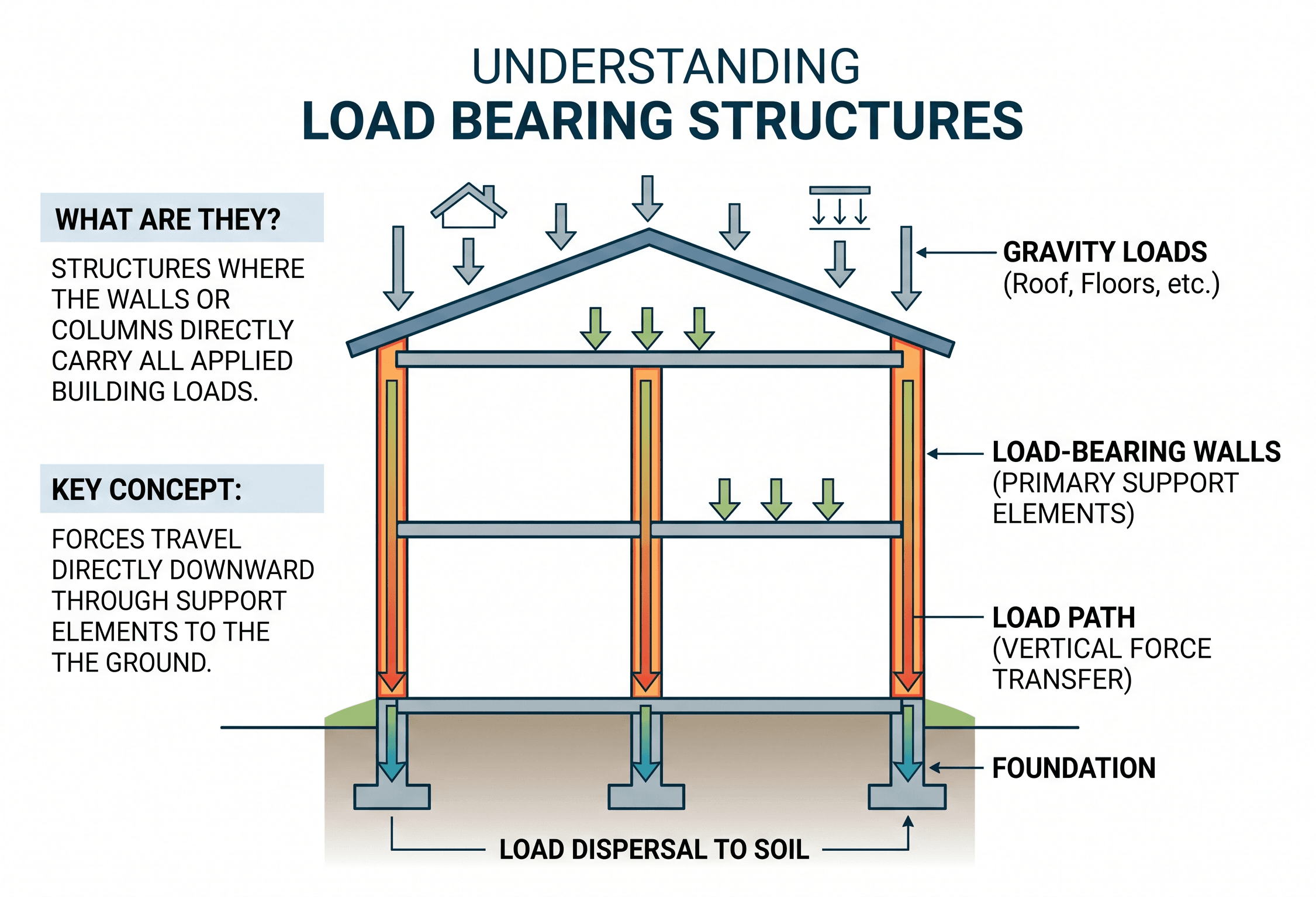
First notice the continuity of support. A slab, beam, wall, or column only performs correctly when the element below it can accept the load and pass it onward without overstress, instability, or excessive movement.
What is a load bearing structure?
A load bearing structure is a building, bridge, tower, wall system, frame, or other structural system in which specific elements carry applied loads and transfer them to the ground. In buildings, these elements may include bearing walls, beams, girders, columns, slabs, trusses, shear walls, braced frames, diaphragms, footings, piles, or mat foundations.
The phrase is often used casually to describe a “load bearing wall,” but the engineering meaning is broader. A wall can carry vertical gravity loads, lateral shear, out-of-plane wind pressure, or a combination of actions. A beam may carry floor loads while also acting as a collector for lateral forces. A slab may span to beams and also distribute diaphragm forces into the lateral system.
The central idea is load path. Every structural force needs a continuous route through the structure into stable support. For background on how engineers evaluate reactions, internal forces, and member behavior, start with structural analysis. For the actions applied to the system, review structural loads.
Load bearing is a system behavior, not just a label. A member is only truly load bearing if it receives load, has adequate capacity, and has a dependable support path below it.
How loads move through a structure
Loads usually begin at surfaces: people and furniture on floors, snow on roofs, wind on walls, equipment on platforms, or seismic inertia distributed through mass. Those loads are collected by local elements, transferred into primary members, delivered into vertical supports, and finally resisted by foundations and soil.
Typical gravity load path
A simple floor system might carry load from slab to beam, beam to girder, girder to column, column to footing, and footing to soil. In a bearing wall building, the path may be floor joists to bearing walls, bearing walls to continuous footings, and footings to soil. In a concrete building, the path may be slab to columns or walls, then into pile caps or a mat foundation.
Typical lateral load path
Wind and seismic loads require a lateral system. Loads may move from cladding into floors and roof diaphragms, then into collectors, chords, shear walls, braced frames, moment frames, foundations, and ground. Missing collectors, weak diaphragm connections, or discontinuous shear walls can make an otherwise strong structure behave poorly.
In practice, load path tracing is one of the fastest ways to find design problems. If an engineer cannot clearly explain where a force goes next, the detail probably needs more review.
Common types of load bearing structures
Load bearing systems vary by material, height, span, occupancy, construction method, and architectural layout. The best system is not always the strongest one on paper; it is the one that carries loads efficiently while meeting cost, schedule, fire, vibration, durability, and layout requirements.
| System type | How it carries load | Common uses | Main engineering concern |
|---|---|---|---|
| Bearing wall system | Walls support floors, roof, and sometimes lateral forces | Residential, masonry, low-rise buildings | Openings, wall alignment, foundation continuity |
| Beam and column frame | Floors span to beams and columns | Commercial, industrial, multi-story structures | Connections, stability, lateral system coordination |
| Reinforced concrete system | Slabs, beams, columns, and walls act together | Parking, podiums, towers, institutional buildings | Cracking, punching shear, reinforcement detailing |
| Steel frame system | Steel beams, columns, braces, and moment frames resist loads | Long-span and multi-story buildings | Buckling, connection design, fire protection |
| Timber or mass timber system | Joists, beams, panels, posts, and shear walls transfer loads | Residential, schools, offices, mid-rise buildings | Moisture, vibration, creep, connection behavior |
| Hybrid system | Multiple materials share gravity and lateral resistance | Mixed-use, renovations, podium structures | Differential movement and transfer details |
To compare common structural material decisions, continue with concrete design, steel design, and timber design.
What controls the design?
A load bearing structure is checked against multiple limit states. Strength is essential, but it is rarely the only design driver. Serviceability, stability, stiffness, vibration, fire resistance, durability, constructability, and foundation movement often control member size or system selection.
Start with loads and geometry → identify gravity and lateral load paths → choose the structural system → check strength → check stability → check deflection, drift, vibration, and cracking → verify foundations and connections → review constructability and inspection access.
Strength
Strength checks confirm that beams, walls, slabs, columns, connections, and foundations can resist factored demand. These checks may involve bending, shear, axial compression, tension, combined loading, punching shear, bearing, sliding, overturning, or connection limit states.
Serviceability
A structure can be strong enough yet still perform poorly. Excessive deflection can crack finishes, pond water, bind doors, damage partitions, or create user discomfort. Lateral drift can damage facades, stairs, elevators, and nonstructural components.
Stability
Stability checks address buckling, overturning, sliding, second-order effects, torsion, diaphragm flexibility, unbraced lengths, and global system behavior. Slender members, discontinuous supports, and poorly braced frames often make stability more critical than simple stress checks.
Before accepting a design, ask: “If this member takes load, what supports it below, and what happens if that support moves, cracks, buckles, or is altered later?”
Basic equations behind load bearing behavior
Full structural design requires code-specific load combinations, material design equations, and project-specific assumptions. Still, several simple relationships help explain how load bearing structures are evaluated conceptually.
Demand versus capacity
A member or system is acceptable only when available capacity exceeds the load effect it must resist. Engineers usually apply load factors, resistance factors, safety factors, and serviceability limits depending on the design method and material.
Tributary area load estimate
For many gravity systems, load begins as an area load on a floor or roof. The load assigned to a beam, wall, or column is often estimated using tributary area.
- P Resulting load on the member, commonly lb, kip, N, or kN.
- q Uniform area load, commonly psf, kPa, or kN/m².
- At Tributary area supported by the member, commonly ft² or m².
Stress check concept
For a simplified axial member, average stress is load divided by area. Real design must also consider slenderness, eccentricity, material behavior, connections, imperfections, and code factors.
These equations are not substitutes for a full design procedure. They are useful for understanding why larger tributary areas, heavier loads, smaller sections, eccentric loading, and interrupted supports can quickly increase structural demand.
Worked example: tracing a floor load path
Example
Assume a floor area carries a service load of 75 psf over a tributary area of 160 ft² to an interior beam. The approximate service load delivered to that beam segment is:
That 12-kip service load is not the end of the design. The beam must transfer force to its supports, the supports must transfer reactions into columns or walls, and those vertical elements must continue the load path into foundations. If the beam bears on a wall, the wall below must be aligned, continuous, and capable of carrying the concentrated reaction.
A practical check is to follow the load with your finger on the framing plan. If the load jumps to an opening, stops at an unsupported partition, lands on a transfer beam, or reaches a foundation that was not designed for it, the structure needs deeper review.
Small tributary assumptions can create large mistakes. Doubling the supported area doubles the gravity load before any load factors or combination effects are applied.
Engineering judgment and field reality
Field conditions rarely match clean classroom diagrams. Existing buildings may contain hidden headers, modified walls, deteriorated wood, corroded steel, cracked masonry, undocumented openings, unreinforced foundations, or load paths altered by renovations. A wall that looks nonstructural may brace framing, support joists, carry a beam pocket, or participate in lateral resistance.
In new construction, the design can still fail in practice if sequencing, temporary bracing, tolerances, or connection installation are ignored. Some members are not stable until the entire system is complete. A steel frame may need temporary bracing during erection. Masonry walls may need bracing before diaphragms are connected. Concrete members may need shoring until adequate strength is reached.
Do not assume a wall is safe to remove because it runs parallel to joists. Verify framing direction, supports above and below, lateral function, foundation support, and any hidden beams or point loads.
Experienced engineers also look for discontinuities: stacked walls that shift between floors, columns landing on transfer beams, large openings near supports, roof equipment added after construction, slab penetrations near columns, and foundation settlement that changes load distribution.
When this breaks down
Load bearing logic breaks down when the assumptions behind the load path are wrong. The most common issue is not a single bad equation; it is a mismatch between the model and the real structure. For example, an analysis may assume a continuous support, but the field condition may include an opening, notch, corroded bearing plate, deteriorated sill, or incomplete connection.
It also breaks down when vertical and lateral systems are treated separately even though they interact. A wall may carry gravity load while also serving as a shear wall. A floor diaphragm may distribute lateral forces while supporting gravity loads. Removing or weakening one element can affect both systems.
- Openings: Doors, windows, shafts, and mechanical penetrations can interrupt load paths and concentrate forces.
- Transfer conditions: Columns or walls that do not stack create high local demand in transfer beams, slabs, or girders.
- Foundation movement: Settlement can redistribute loads and cause cracking, rotation, or differential movement.
- Deterioration: Moisture, corrosion, fire damage, biological decay, and freeze-thaw damage can reduce capacity.
- Unbraced construction stages: A partially built structure may not yet have the final load-resisting system in place.
Common pitfalls and engineering checks
Most load bearing mistakes come from assuming the structure is simpler than it really is. A good review checks the load path in plan, elevation, section, and field conditions.
- Assuming a partition is non-load bearing without checking framing and supports.
- Ignoring lateral load paths while focusing only on vertical gravity loads.
- Creating openings without headers, collectors, jamb reinforcement, or foundation review.
- Checking member strength but not connection, bearing, or anchorage capacity.
- Forgetting that temporary construction conditions may govern stability.
- Overlooking deflection, drift, vibration, cracking, and serviceability limits.
Removing a wall or column is not just a local change. It can redirect load into members and foundations that were never intended to carry it.
| Check | Question to ask | Why it matters | Related issue |
|---|---|---|---|
| Vertical continuity | Does each support continue to foundation? | Prevents hidden transfer problems | Stacked walls, columns, footings |
| Lateral resistance | Where do wind and seismic loads go? | Prevents drift, torsion, and instability | Diaphragms, shear walls, frames |
| Connection capacity | Can the joint transfer the required force? | Weak connections can fail before members | Anchors, welds, bolts, bearing |
| Serviceability | Will movement damage finishes or function? | Strength alone does not ensure performance | Deflection, vibration, cracking |
| Durability | Will materials keep capacity over time? | Deterioration changes real resistance | Moisture, corrosion, decay, fire |
Visualizing load bearing behavior
The most useful way to visualize a load bearing structure is to imagine every load as a stream of force. Gravity loads usually flow downward through floors, beams, walls, columns, and foundations. Lateral loads often flow sideways through diaphragms and collectors before reaching shear walls, braced frames, or moment frames.
A clean structural concept avoids “orphan loads.” No roof load, floor load, wall reaction, equipment support, or lateral force should terminate without a deliberate receiving element. This is why engineers review plans, sections, details, and foundation drawings together rather than in isolation.
The key visual habit is continuity: each member should answer what it supports, what supports it, and how forces move across connections.
Relevant standards and design references
Load bearing structures are governed by the adopted building code, referenced material standards, and project-specific criteria. Always verify the locally adopted editions and amendments for real design work.
- International Building Code (IBC): Establishes building code requirements, occupancy considerations, structural design references, and minimum safety provisions used by many jurisdictions.
- ASCE/SEI 7: Provides minimum design loads and load combinations for buildings and other structures, including dead, live, snow, wind, seismic, rain, and flood-related actions.
- ACI 318: Governs structural concrete design, including slabs, beams, columns, walls, shear, flexure, axial strength, development length, and detailing.
- AISC Steel Construction Manual and AISC 360: Provide structural steel design requirements for members, stability, connections, composite systems, and strength checks.
- National Design Specification for Wood Construction (NDS): Provides design provisions for wood members, connections, adjustment factors, and load duration behavior in timber structures.
Frequently asked questions
A load bearing structure is a structural system where elements such as walls, beams, columns, slabs, frames, or foundations carry loads and transfer them safely into the ground. The important engineering idea is a complete load path, not just whether one visible wall or member appears strong.
No. Some walls are partitions that divide space, while others support gravity loads, resist lateral loads, brace framing, or support concentrated reactions. The only reliable way to know is to review framing, supports, foundations, drawings, and field conditions.
A load bearing wall usually supports load along a line, while a column supports load at a concentrated point. Both require adequate capacity, stable support below, proper connections, and foundations that can resist the resulting forces.
A load bearing wall can sometimes be removed, but only after the load is safely redirected through a properly designed beam, posts, connections, and foundations. The replacement system must account for gravity loads, lateral effects, deflection, bearing, and construction sequencing.
Warning signs can include new cracks, sagging floors, sloped floors, sticking doors, wall separation, foundation movement, crushed bearing areas, corrosion, moisture damage, vibration, or distress around openings. These signs do not always prove structural danger, but they do justify closer evaluation.
Summary and next steps
Load bearing structures are the systems that collect, resist, and transfer forces through a building or structure. Their performance depends on much more than isolated member strength. A safe structure needs continuous load paths, stable supports, adequate connections, controlled movement, durable materials, and foundations that match the demands above.
The most useful engineering habit is to trace forces from their source to the ground. When that path is interrupted by an opening, transfer condition, weak connection, foundation issue, or construction-stage instability, the design needs additional review. Strong structures are usually the result of clear load paths and disciplined detailing.
In practice, load bearing behavior connects directly to structural analysis, structural loads, material design, foundation behavior, and structural failure prevention. Treat the structure as a system, then verify each part of the system with the correct design method and code reference.
Where to go next
Continue your learning path with these related structural engineering topics.
-
Study structural analysis
Learn how engineers calculate reactions, shear, moment, axial force, deflection, and member behavior.
-
Review load path analysis
Deepen the most important concept behind load bearing structures: how forces move through the system.
-
Learn about structural failure
See how missing load paths, poor detailing, deterioration, and underestimated loads can lead to distress or collapse.