Key Takeaways
- Core idea: Overcurrent protection detects current above an acceptable level and opens the circuit before conductors, switchgear, transformers, motors, or loads are damaged.
- Engineering use: Power systems use overcurrent protective devices, or OCPDs, such as fuses, breakers, relays, and overload devices to isolate abnormal current conditions.
- What controls it: Device rating, pickup setting, time delay, trip curve, available fault current, conductor ampacity, load behavior, and coordination with nearby devices control the protection scheme.
- Practical check: A protective device must trip at the right current, coordinate with other devices, and safely interrupt the available fault current at its installed location.
Table of Contents
Introduction
Overcurrent protection is the use of fuses, circuit breakers, protective relays, and related devices to detect excessive current and interrupt a circuit before unsafe heating, equipment damage, or fault energy spreads through a power system. In engineering practice, the goal is not just to trip fast; it is to trip the correct device at the correct time.
Overcurrent Protection in a Power System
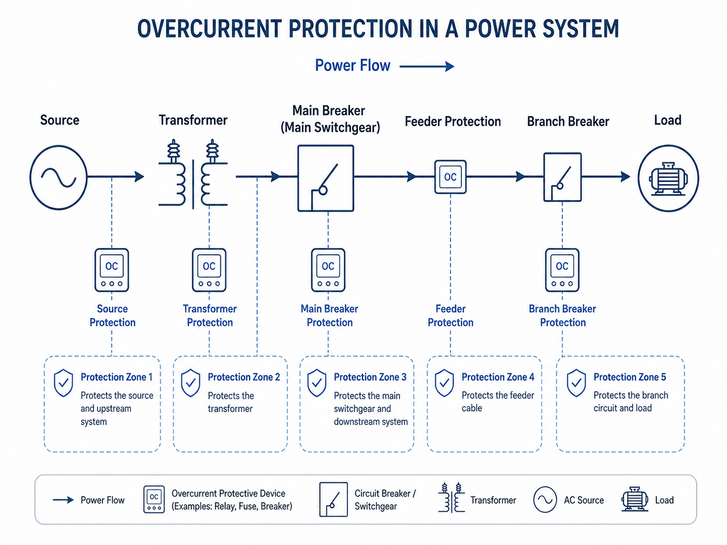
Notice that the protective device is not a random add-on. Its location, current rating, interrupting capability, and trip behavior define which part of the system it can protect.
What Is Overcurrent Protection?
Overcurrent protection is a power system protection function that responds when current rises above the level that conductors or equipment can safely carry. An overcurrent protective device opens a circuit when current exceeds a safe value for the protected conductors or equipment.
Overcurrent is not always a fault. Some overcurrent conditions are temporary and expected, such as motor starting or transformer energization. Others, such as short circuits and ground faults, require rapid interruption. The protection challenge is telling the difference quickly enough to protect equipment without causing unnecessary trips.
The protective device may be a simple fuse, a molded-case breaker, a low-voltage power breaker, a motor overload relay, or a relay-controlled breaker using current transformers. These devices are commonly called overcurrent protective devices, or OCPDs.
A properly applied overcurrent protective device should protect the circuit it serves without unnecessarily tripping upstream equipment or allowing downstream damage to continue.
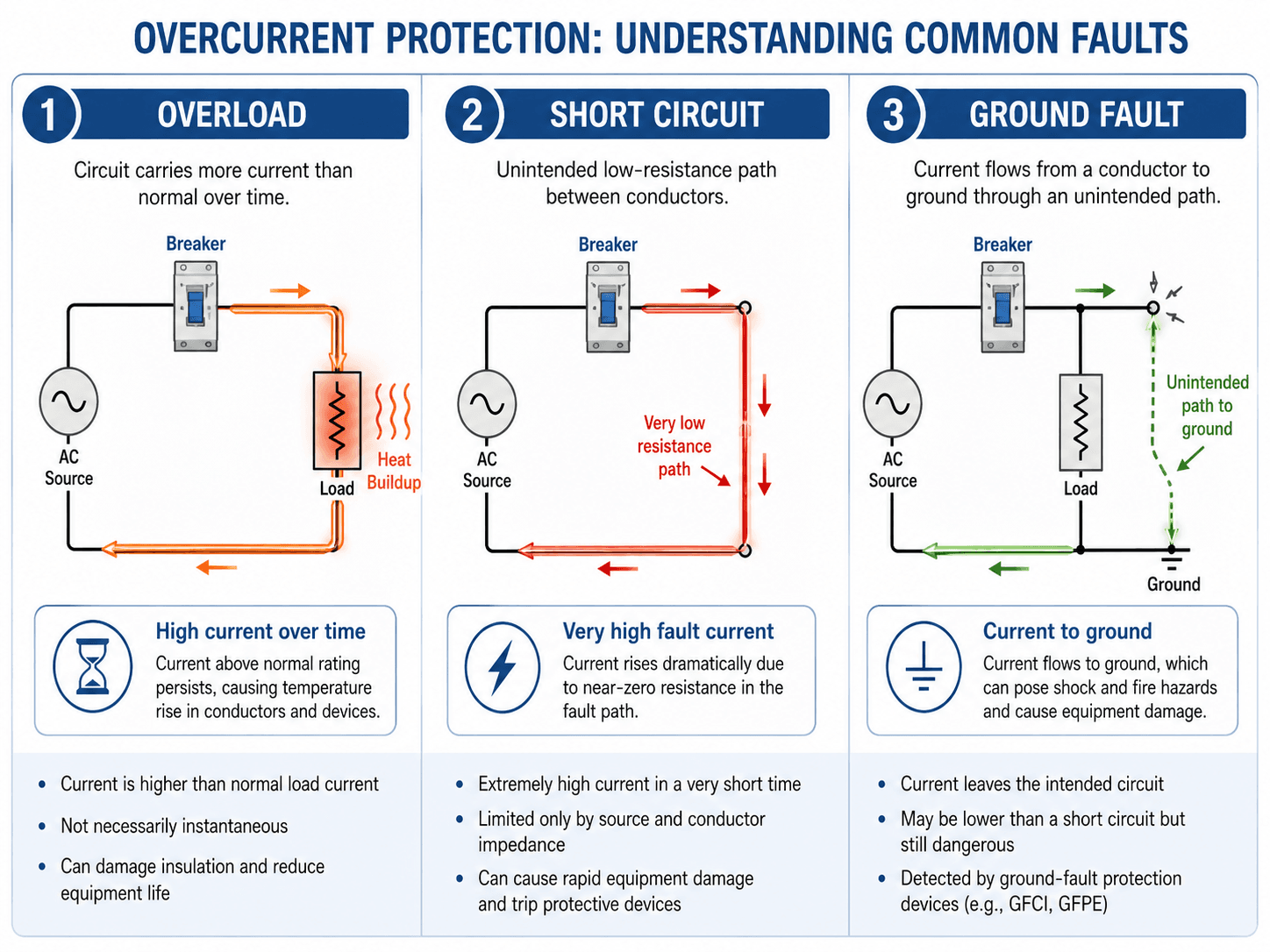
Overload, Short Circuit, and Ground Fault
Most confusion around overcurrent protection comes from treating every high-current event as the same problem. In reality, overloads, short circuits, and ground faults behave differently and may require different device characteristics.
| Condition | What is happening | Typical protection response |
|---|---|---|
| Overload | The circuit carries more current than intended for longer than the conductors or equipment can tolerate. | Thermal trip element, overload relay, fuse melting curve, or inverse-time breaker response. |
| Short circuit | A low-impedance path forms between conductors, causing current to rise rapidly. | Instantaneous trip, short-time trip, current-limiting fuse, or relay-controlled breaker operation. |
| Ground fault | Current flows from an energized conductor to ground or bonded metal through an unintended path. | Ground-fault relay, residual current detection, zero-sequence sensing, GFCI, GFPE, or phase overcurrent depending on the system. |
| Arc fault | An arcing condition produces abnormal current and heat, but the current may not look like a simple bolted short circuit. | Dedicated arc-fault detection may be needed where the waveform, current level, or installation type requires it. |
Types of Overcurrent Protection
The phrase “overcurrent protection” can refer to several functions. Some protect against sustained overloads, some clear high-magnitude faults quickly, and some add directional or ground-current logic for more complex power systems.
| Type | What it protects against | Common device or function |
|---|---|---|
| Overload protection | Current above normal load current that persists long enough to overheat conductors, windings, or equipment. | Thermal breaker, overload relay, fuse time-current curve, electronic long-time trip. |
| Instantaneous overcurrent | High-magnitude short-circuit current that should be cleared with little intentional delay. | ANSI 50 relay function, magnetic trip, instantaneous breaker element. |
| Time overcurrent | Fault current that should be cleared with a time delay so downstream devices can operate first. | ANSI 51 relay function, inverse-time relay, short-time breaker function. |
| Ground overcurrent | Ground-fault current returning through ground, bonding paths, or residual current paths. | 50G, 51G, 50N, 51N, ground-fault relay, residual sensing. |
| Directional overcurrent | Fault current where direction matters because the system has multiple sources or backfeed paths. | ANSI 67 directional overcurrent relay function. |
Directional overcurrent is especially useful in systems with parallel feeders, generators, distributed energy resources, or tie breakers, where the relay must know not only how much current is flowing, but also which direction the fault current is flowing.
Main Overcurrent Protection Devices
Overcurrent protection is implemented with devices that sense current, respond to a selected current-time characteristic, and interrupt or command interruption of the circuit. The best device depends on the voltage level, load type, available fault current, maintainability, and required coordination.
| Device | Best use | Engineering notes |
|---|---|---|
| Fuse | Simple, fast, current-limiting protection for feeders, transformers, equipment, and branch circuits. | Current-limiting fuses can reduce peak let-through current and fault energy when applied within their current-limiting range. |
| Circuit breaker | Resettable protection for panels, switchboards, switchgear, feeders, and branch circuits. | Breakers may include thermal, magnetic, electronic, long-time, short-time, instantaneous, and ground-fault functions. |
| Protective relay | Medium-voltage, high-value, or adjustable power system protection schemes. | Relays usually receive current through CTs and trip a breaker when pickup and time-delay logic is satisfied. |
| Motor overload relay | Motor thermal overload protection. | A motor overload relay typically commands a starter or contactor to open during sustained overload; it is not normally the device that interrupts high short-circuit current. |
| Recloser or sectionalizer | Distribution feeder automation and fault isolation. | These devices support service restoration and sectionalizing logic on overhead or distribution systems. |
The device name alone does not prove the circuit is protected correctly. The device must have suitable voltage rating, continuous current rating, interrupting rating, trip curve, enclosure, environmental rating, and coordination with other protective devices.
If the device is protecting conductors, ampacity and temperature limits are central. If it is protecting equipment, damage curves, manufacturer limits, and equipment withstand capability may control the setting.
How Overcurrent Protection Works
An overcurrent protective device compares measured or sensed current against a response characteristic. If current exceeds the device pickup level long enough, the device opens the circuit directly or sends a trip signal to a breaker.
Current sensing
Low-voltage breakers may sense current internally using thermal-magnetic or electronic trip units. Relay-based systems usually sense current through current transformers. The relay does not carry the main power current; it measures a scaled secondary current and decides whether to trip.
Pickup and time delay
Pickup is the current level at which the device begins to respond. Time delay determines how long the device waits before tripping. This delay is not simply a slowdown; it is what allows downstream devices to clear local faults before upstream devices interrupt a larger portion of the system.
Interruption
Opening a circuit under fault current is a severe duty. The protective device or breaker must be able to interrupt the available fault current without failing. This is why interrupting rating and short-circuit study results matter as much as the trip setting.
- \(I_{\text{fault}}\) Approximate fault current available at the fault location, usually evaluated in amperes or kiloamperes.
- \(V_{\text{source}}\) System driving voltage at the source side of the fault.
- \(Z_{\text{total}}\) Total source, transformer, conductor, and equipment impedance between the source and the fault.
This simplified relationship explains why a close-in fault near a transformer can produce much higher current than a fault at the end of a long feeder. In actual studies, fault current depends on source impedance, transformer impedance, conductor impedance, motor contribution, generator contribution, grounding configuration, and whether the fault is three-phase, line-to-line, line-to-ground, or arcing.
Time-Current Curves and Selective Coordination
Time-current curves show how long a device takes to trip at different current levels. They are one of the most important tools for understanding overcurrent protection because they connect current magnitude, trip time, device behavior, and coordination.
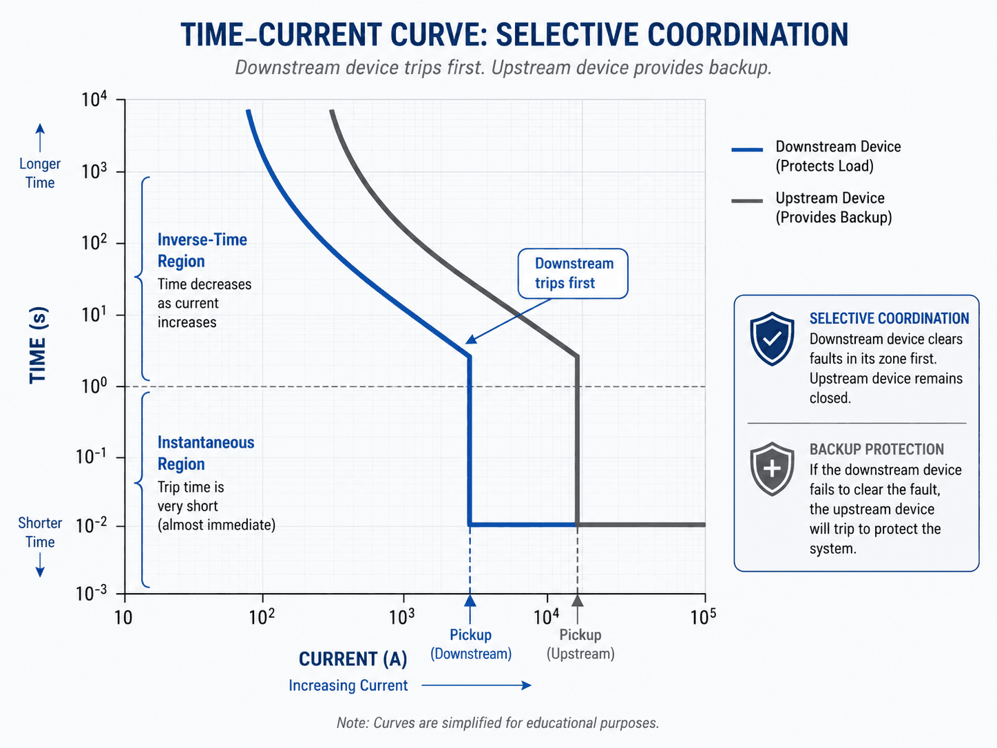
Inverse-time behavior
In an inverse-time region, the trip time decreases as current increases. This lets a device tolerate moderate temporary current, such as motor starting or transformer inrush, while still clearing larger faults faster.
Instantaneous behavior
The instantaneous region responds very quickly when current exceeds a high threshold. It is valuable for high-magnitude faults, but if set too low it can defeat coordination by tripping upstream devices before downstream devices have time to operate.
Relay functions used in overcurrent protection
Relay numbers are a compact way to describe protection functions. In overcurrent protection, ANSI 50 and ANSI 51 are especially common, while ground and directional elements are added when the system requires more selective fault detection.
| Relay function | Meaning | Typical use |
|---|---|---|
| 50 | Instantaneous overcurrent | Fast clearing for high-magnitude faults with little intentional delay. |
| 51 | Time overcurrent | Delayed or inverse-time clearing so downstream devices can operate first. |
| 50G / 51G | Ground overcurrent | Ground-fault detection using ground current, residual current, or zero-sequence measurement. |
| 50N / 51N | Neutral overcurrent | Neutral or residual current protection depending on the system grounding and CT configuration. |
| 67 | Directional overcurrent | Fault detection that considers current direction in looped, paralleled, or multi-source systems. |
Maximum and Minimum Fault Current Both Matter
A common mistake is checking only the highest available short-circuit current. Maximum fault current is critical for interrupting rating and equipment duty, but minimum fault current is also important because the protective device still needs enough current to detect and clear the fault.
| Fault-current check | Why it matters | Engineering implication |
|---|---|---|
| Maximum fault current | Determines whether the OCPD can safely interrupt the worst-case available short-circuit current. | Interrupting rating and equipment short-circuit withstand ratings must be adequate. |
| Minimum fault current | Determines whether the protective device will actually detect and trip for a remote or high-impedance fault. | Long feeders, weak sources, high-impedance faults, and some inverter-based sources may require sensitive or specialized protection. |
| Fault-current direction | Determines whether a relay can distinguish downstream faults from backfeed or reverse power flow. | Directional elements may be needed in systems with generators, tie breakers, or distributed energy resources. |
A device can be too weak in two different ways: it may be unable to interrupt a high fault current, or it may be unable to detect a low fault current at the far end of the protected circuit.
Key Selection Criteria for Overcurrent Protective Devices
Selecting an overcurrent protective device is not just choosing an ampere rating. Engineers review the load, conductor ampacity, equipment withstand capability, available fault current, device curve, and coordination with adjacent devices.
| Selection item | Why it matters | Engineering implication |
|---|---|---|
| Continuous current rating | The device must carry expected load current without nuisance tripping. | Do not oversize the device beyond what the protected conductors and equipment can safely handle. |
| Voltage rating | The device must be suitable for the system voltage and application. | Voltage rating affects insulation, arc interruption, and suitability for AC or DC systems. |
| Interrupting rating | The device must safely interrupt available fault current at its installation point. | A short-circuit study is often needed before final device selection. |
| Trip curve or relay characteristic | The current-time response determines whether the device trips quickly, slowly, or selectively. | Curve shape must fit load behavior, downstream devices, and backup protection needs. |
| Inrush and starting current | Motors, transformers, and capacitors can draw temporary high current during energization. | Settings should avoid nuisance trips while still protecting against real faults. |
| AC or DC system | DC interruption can be more difficult because current does not naturally pass through zero like AC current. | Device ratings must match the system type, voltage, and interrupting duty. |
| Coordination with adjacent devices | One device rarely works alone in a power system. | The nearest suitable downstream device should clear the fault before upstream devices trip. |
Selective Coordination Workflow
Selective coordination is the practical design process that turns overcurrent protection from a collection of devices into a system. The goal is to isolate the smallest practical portion of the system while preserving backup protection.
Start at the load and work upstream. Define the protected zone, confirm conductor and equipment ratings, estimate normal load current, determine available fault current, select the downstream device, compare its time-current curve with the upstream device, then adjust pickup and delay so the downstream device clears local faults first while the upstream device remains available as backup.
| Coordination check | What to look for | Why it matters |
|---|---|---|
| Downstream device clears first | The downstream fuse, breaker, or relay curve should operate before the upstream device for faults in the downstream zone. | This limits the outage to the smallest practical part of the system. |
| Upstream backup remains available | The upstream device should still trip if the downstream device fails or if the fault is outside the downstream zone. | Backup protection prevents a single device failure from leaving the system unprotected. |
| Inrush does not cross the trip curve | Transformer energization, motor starting, and capacitor switching should not fall inside the unwanted trip region. | Ignoring inrush is a common reason for nuisance trips after commissioning. |
| Available fault current is interruptible | The device interrupting rating should exceed the available short-circuit current at that point. | A device that trips but cannot interrupt safely is not an acceptable protective solution. |
| Settings match the one-line diagram | Relay CT ratios, breaker locations, trip coils, and protected zones should match the actual system configuration. | Coordination curves are only useful if they represent the installed equipment and wiring. |
Practical Example: Feeder and Branch Breaker Coordination
Consider a 480 V panel feeding a branch circuit. The feeder breaker is rated 400 A, the branch breaker is rated 100 A, the normal branch load is 72 A, and the available short-circuit current at the branch panel is 18 kA.
Device rating check
The 100 A branch breaker is above the 72 A normal load, so it can carry the expected load without tripping during normal operation. If the branch breaker has a 25 kA interrupting rating and the available short-circuit current is 18 kA, the interrupting rating is above the available fault current at that point.
Coordination check
The engineer would compare the 100 A branch breaker curve against the 400 A feeder breaker curve. For faults on the branch circuit, the branch breaker should clear first. The feeder breaker should remain closed unless the branch breaker fails to clear the fault or the fault is on the feeder side.
Engineering interpretation
This example shows why ampere rating, interrupting rating, and trip curves all matter. A breaker can be correctly sized for load current but still be unacceptable if its interrupting rating is too low or if its curve does not coordinate with the upstream device.
Coordination is not judged from ampere ratings alone. Two devices with different ampere ratings can still overlap on a time-current curve and trip in an undesirable order.
What Overcurrent Protection Does Not Replace
Overcurrent protection is essential, but it is not the same as every other electrical safety or protection function. A standard breaker or fuse may protect conductors and equipment from excessive current while still leaving other hazards to separate protection methods.
| Misconception | Correct interpretation |
|---|---|
| A breaker protects people from all electric shock hazards. | A standard breaker mainly protects conductors and equipment from overcurrent. GFCI, GFPE, bonding, grounding, and other protective measures address specific shock and ground-fault risks. |
| Surge protection is the same as overcurrent protection. | Surge protection limits transient overvoltage, while overcurrent protection responds to excessive current. |
| A larger breaker is a safe way to stop nuisance trips. | Oversizing a breaker can defeat conductor and equipment protection if ampacity and equipment ratings are not checked. |
| Grounding alone clears faults. | Grounding and bonding help create an effective fault-current path, but an OCPD still has to detect and interrupt the fault. |
| Arc-flash risk disappears if a breaker is installed. | Arc-flash energy depends on available fault current, clearing time, working distance, equipment configuration, and protective device settings. |
Engineering Judgment and Field Reality
Real power systems rarely behave like clean textbook diagrams. Transformer inrush, motor acceleration, variable frequency drives, distributed generation, long feeders, maintenance changes, and equipment replacements can all change how overcurrent protection behaves.
A protection setting that worked on the original installation may become weak after a transformer upgrade increases available fault current. A breaker replacement may change trip-curve behavior. A new inverter or generator may add fault-current contribution from a direction the original coordination study did not consider.
The most reliable review combines the one-line diagram, actual breaker and relay settings, CT ratios, conductor data, transformer impedance, measured load current, and the current equipment lineup. A curve plot alone can hide field wiring or configuration problems.
When This Breaks Down
Simplified overcurrent protection explanations break down when the system has changing sources, multiple fault-current paths, unusual load behavior, or coordination requirements that cannot be satisfied with a simple fixed trip point.
- Multiple sources: Generators, inverters, tie breakers, and utility backfeeds can change fault-current direction and magnitude.
- High inrush loads: Transformers, large motors, and capacitor banks may create temporary current that looks like a fault to poorly selected settings.
- Weak fault current: Long feeders or high-impedance faults may not produce enough current for a simple instantaneous element to operate reliably.
- Device curve overlap: Upstream and downstream devices may both trip for the same event if their time-current curves are not separated properly.
- Outdated studies: Equipment replacements, transformer changes, and new loads can make old coordination assumptions invalid.
Common Mistakes and Practical Checks
Overcurrent protection mistakes usually happen when a device is treated as a generic safety component instead of part of a coordinated electrical system. The most common problems involve rating, coordination, load behavior, and misunderstanding what a device is actually protecting.
- Oversizing a breaker to stop nuisance trips: This can leave conductors or equipment without adequate protection.
- Ignoring interrupting rating: A device must safely interrupt the available fault current, not merely detect it.
- Confusing overload protection with short-circuit protection: Motor overload relays and branch short-circuit protection perform different jobs.
- Ignoring minimum fault current: Remote faults and high-impedance faults may not create enough current to operate a poorly selected device.
- Assuming upstream backup is enough: Backup protection may protect the system, but it can also create a larger outage than necessary.
- Skipping the actual one-line review: Relay settings, breaker locations, CT wiring, and trip circuits must match the physical system.
Do not solve nuisance tripping by increasing the device rating without checking conductor ampacity, equipment ratings, load current, inrush behavior, and coordination with upstream protection.
Relevant Manuals, Standards, and Design References
Overcurrent protection is closely tied to project requirements, equipment ratings, and coordination studies. Engineers commonly use code requirements, owner standards, relay manuals, breaker data, fuse curves, and short-circuit calculations together rather than relying on a single rule of thumb.
- U.S. Army technical manual: overcurrent protective device guidance in TM 5-811-14 explains protective devices, time-current characteristics, and the information needed for coordinated power system protection.
- Code context: For building and facility wiring, NEC Article 240 is commonly associated with general requirements for overcurrent protection and overcurrent protective devices, while equipment-specific rules may also appear in other NEC articles such as motor, transformer, and branch-circuit sections.
- Project-specific criteria: Owner standards, utility requirements, facility design criteria, equipment listings, and applicable electrical codes may control final device selection and settings.
- Engineering use: References and manufacturer data are used with short-circuit studies and coordination curves to confirm that the selected device protects the intended zone and safely interrupts fault current.
Frequently Asked Questions
Overcurrent protection is the use of fuses, circuit breakers, protective relays, and related devices to detect current above an acceptable level and interrupt the circuit before conductors or equipment are damaged.
Overload protection responds to current that is too high for too long, usually because a load exceeds its normal rating. Short-circuit protection responds to very high fault current caused by a low-impedance path between conductors or from a conductor to ground.
Common overcurrent protection devices include fuses, molded-case circuit breakers, low-voltage power circuit breakers, protective relays with current transformers, motor overload relays, reclosers, and sectionalizers.
Selective coordination helps ensure that the protective device closest to the fault trips first while upstream devices remain closed unless backup protection is needed. This limits outages, protects equipment, and improves system reliability.
No. Ground-fault protection responds to current leaving the intended circuit path and returning through ground or bonding paths. Overcurrent protection is broader and includes overload, short-circuit, and some ground-fault conditions depending on the device and settings.
Summary and Next Steps
Overcurrent protection protects power systems by detecting excessive current and opening the appropriate device before conductors, switchgear, transformers, motors, or loads are damaged. The key is not only detecting high current, but also identifying the right device, trip curve, rating, and protected zone.
A strong overcurrent protection review checks load current, conductor ampacity, available fault current, minimum fault current, interrupting rating, time-current curves, inrush behavior, selective coordination, and backup protection. The best designs balance safety, reliability, maintainability, and outage selectivity.
Where to go next
Continue your learning path with related Turn2Engineering power systems resources.
-
Protective Relays
Learn how relays detect abnormal electrical conditions and trip breakers in power systems.
-
Switchgear
See how breakers, relays, bus structures, and switching equipment are arranged in practical power systems.
-
Differential Protection
Compare overcurrent protection with a zone-based protection method used for transformers, buses, generators, motors, and lines.