Key Takeaways
- Core idea: Grounding techniques connect electrical systems, equipment, and conductive parts to earth or a reference point, while bonding and equipment grounding conductors help create the effective fault-current path back to the source.
- Engineering use: Power systems engineers use grounding to control touch voltage, step voltage, surge effects, ground faults, equipment damage, and protective device operation.
- What controls it: Source grounding, bonding continuity, conductor impedance, electrode layout, soil resistivity, and protective device coordination determine whether a grounding system works as intended.
- Practical check: A ground rod is not the same thing as an effective ground-fault current path; the return path to the source is usually the safety-critical part.
Table of Contents
Introduction
Grounding techniques are the methods used to connect electrical systems, equipment enclosures, and conductive parts to earth or a common reference point. In power systems, good grounding stabilizes voltage, limits dangerous potential differences, provides a controlled fault-current path, and helps breakers, fuses, and protective relays isolate faults before people or equipment are harmed.
Grounding vs Bonding at a Glance
The diagram below separates two ideas that are often mixed together: grounding establishes an earth or reference connection, while bonding connects conductive parts so they stay at nearly the same potential.
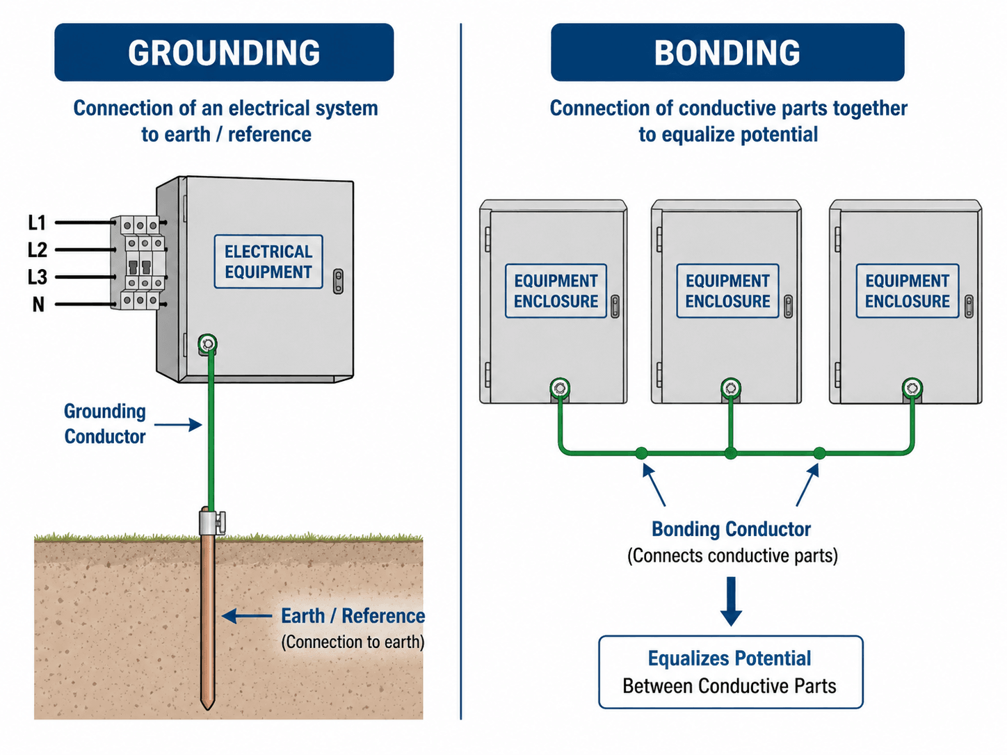
The most important takeaway is that grounding and bonding work together. Grounding establishes a reference to earth, but bonding and equipment grounding conductors often provide the low-impedance path that allows a fault to clear quickly.
What Are Electrical Grounding Techniques?
Electrical grounding techniques are practical methods for connecting power systems, equipment, and conductive parts to earth, to a grounded conductor, or to a shared reference point. In power systems engineering, grounding is not a single wire or a single ground rod. It is a coordinated system of source grounding, equipment grounding, bonding, grounding electrodes, conductors, connections, and protective devices.
A shallow explanation often says grounding “sends electricity into the earth.” That is incomplete. Earth connection can help stabilize voltage and dissipate lightning or surge energy, but a breaker normally trips because fault current returns to the source through an effective low-impedance path. That path is usually created by bonding and equipment grounding conductors, not by soil alone.
A grounding system should be evaluated by what it is supposed to do: stabilize voltage, control overvoltage, limit touch and step voltage, support surge and lightning protection, or carry enough fault current for protective devices to operate.
Grounding Terms That Are Easy to Confuse
Grounding terminology is easy to mix up because several conductors and connections may all look like part of the “ground” system. In design review, each part should be identified by its function, not only by wire color or where it appears in the panel.
| Term | Plain-language role | Normal current? |
|---|---|---|
| Grounded conductor | The intentionally grounded circuit conductor, often the neutral in many systems. | Yes, in systems where it serves as the normal return conductor. |
| Equipment grounding conductor | The conductor that bonds equipment and carries fault current during abnormal conditions. | No, except during faults or abnormal conditions. |
| Grounding electrode conductor | The conductor that connects the system or equipment grounding path to the grounding electrode system. | No normal load current. |
| Bonding jumper | A conductor or connection that provides electrical continuity between conductive parts. | No normal load current, but it may carry fault current. |
| Main bonding jumper | The connection at service equipment that bonds the grounded conductor to the equipment grounding path. | No normal load current on the equipment grounding path, but it is essential during faults. |
| System bonding jumper | The bonding connection used at a separately derived system such as certain transformers or generators. | No normal load current on equipment grounding paths when installed correctly. |
Main Electrical Grounding Techniques
The term grounding techniques can refer to several related but different design actions. Some techniques deal with how the source or neutral is grounded. Others deal with metal equipment enclosures, grounding electrodes, ground grids, lightning protection, or sensitive electronic equipment. Mixing these categories is one of the most common reasons grounding explanations become confusing.
| Grounding technique | Primary purpose | Best used when | Common mistake |
|---|---|---|---|
| System grounding | Connects a source, neutral, or derived system point to ground or through an impedance. | The system needs defined line-to-ground voltages and predictable ground-fault behavior. | Assuming every source has the same neutral-ground bonding requirements. |
| Equipment grounding | Connects non-current-carrying metal parts to an equipment grounding conductor. | Metal enclosures, raceways, skids, frames, and equipment need a safe fault-current path. | Treating the equipment grounding conductor as a normal current-carrying conductor. |
| Bonding | Connects conductive parts together to reduce voltage differences between them. | Multiple metal parts could become energized or sit at different potentials during a fault. | Missing bonding jumpers across painted, flexible, removable, or mechanically interrupted joints. |
| Grounding electrode system | Uses rods, rings, concrete-encased electrodes, plates, or grids to connect the installation to earth. | The installation needs an earth reference, surge dissipation path, or site grounding electrode network. | Assuming one ground rod alone proves the system is safe. |
| Resistance grounding | Places resistance between the system neutral and ground to limit ground-fault current. | Industrial systems need controlled ground-fault current and reliable detection. | Installing a neutral grounding resistor without matching relay settings and thermal duty. |
| Isolated grounding | Provides a separate grounding path for selected sensitive loads while maintaining safety grounding. | Noise-sensitive electronics need reduced grounding noise and the safety path remains intact. | Using “isolated” to mean disconnected from the required bonding and safety grounding system. |
How Grounding Clears Faults
During a ground fault, current leaves the source on an energized conductor, contacts a metal enclosure or conductive part, and must return to the source through a bonded equipment grounding path. If that path has low enough impedance, the fault current rises high enough for the breaker, fuse, or relay to operate.
In code-oriented language, this is often described as an effective ground-fault current path: an intentionally constructed, low-impedance conductive path that carries fault current from the fault point back to the electrical supply source so protective devices can operate.
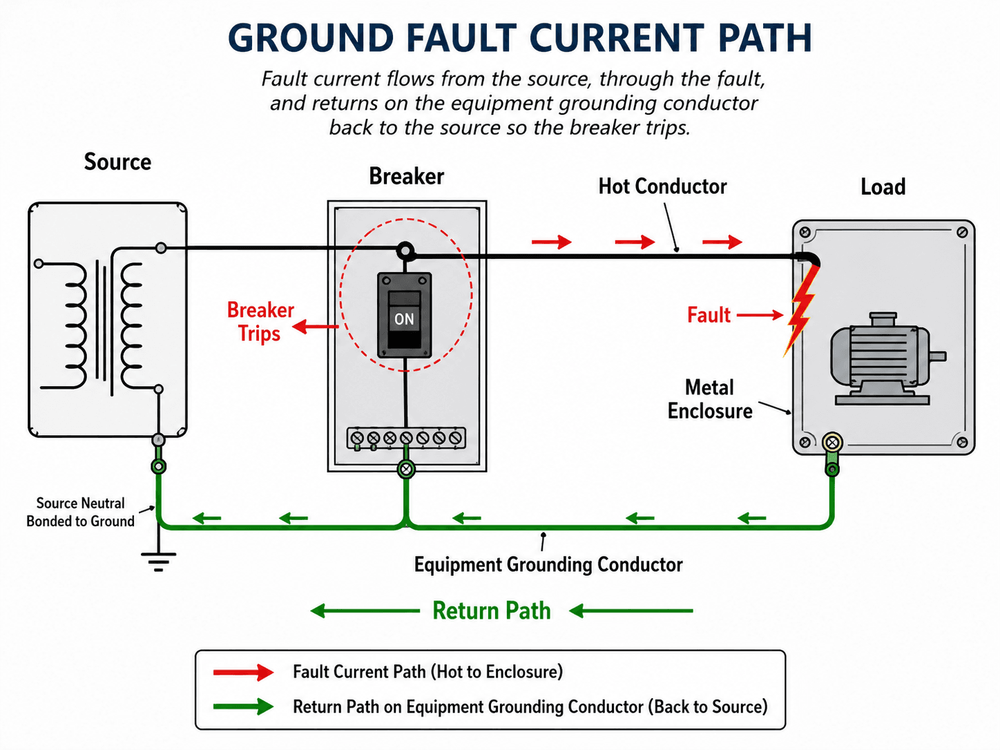
The fault path returns to the source, not just to soil
The equipment grounding conductor is not intended to carry normal load current, but it becomes essential during a fault. The safer design question is not simply “Is there a ground rod?” but “Is there a complete and effective fault-current path back to the source?”
Protective devices depend on current magnitude and time
Overcurrent devices operate based on the amount of current and how long it flows. A loose bonding jumper, corroded clamp, undersized conductor, or broken equipment grounding path can reduce fault current enough to delay clearing and leave exposed metal energized longer than intended. This is why grounding design must be coordinated with overcurrent protection, breaker ratings, fuses, and relay settings.
Power System Grounding Methods Compared
System grounding describes how the source or neutral point is connected to ground. The right method depends on voltage level, service continuity goals, available fault current, relay strategy, equipment insulation, and operating environment.
| Method | How it behaves | Typical engineering use | Important limitation |
|---|---|---|---|
| Solid grounding | The source neutral or grounded point is connected directly to ground. | Common in many low-voltage and utility distribution systems where fast fault clearing is desired. | Ground-fault current can be high, so equipment ratings and protection must be coordinated. |
| Low-resistance grounding | A resistor limits ground-fault current while still allowing protective relays to detect and clear faults. | Medium-voltage industrial systems where damage limitation and selective protection are important. | Requires correct resistor sizing, relaying, and thermal duty review. |
| High-resistance grounding | A higher resistance limits first ground-fault current to a low value. | Industrial facilities where continuity of service may be valuable after a first ground fault. | Fault detection and maintenance discipline are critical; a second fault can become severe. |
| Reactance grounding | Grounding impedance is mainly inductive rather than resistive. | Specialized systems where current limitation and system behavior must be studied carefully. | Can create transient overvoltage concerns if not properly engineered. |
| Ungrounded system | No intentional source connection to ground is provided. | Older or specialized systems where first-fault continuity was historically valued. | Can develop dangerous overvoltages and make fault location difficult. |
High fault current is not automatically bad, and low fault current is not automatically safe. The grounding method must match the protection scheme, equipment ratings, operating philosophy, and maintenance capability. Larger systems often require review with protective relays so the grounding method and protection logic work together.
How to Choose a Grounding Technique
Grounding selection starts with the system source, voltage level, protection strategy, continuity requirements, and site conditions. The same technique is not automatically correct for every installation, and the wrong approach can either fail to clear faults or create unnecessary operating problems.
| System situation | Grounding approach commonly reviewed | Reason it matters |
|---|---|---|
| Low-voltage building service | Solid grounding, bonding, equipment grounding conductors, and grounding electrode system. | Supports stable voltage reference and fast overcurrent device operation during faults. |
| Industrial medium-voltage system | Low-resistance or high-resistance grounding. | Limits ground-fault damage while maintaining a detectable and controlled fault condition. |
| Substation or utility yard | Ground grid, ground rods, surface treatment, and step/touch voltage review. | Controls voltage gradients around high-energy faults and switching events. |
| Sensitive electronics or instrumentation | Isolated grounding only where the safety grounding path remains intact. | Can help reduce electrical noise but must not defeat bonding or fault clearing. |
| Generator, UPS, transformer, or inverter source | Review separately derived system behavior, transfer equipment, and bonding point. | The grounding path must remain effective under alternate-source operation. |
Choose the grounding method by starting with the source and fault-clearing objective, then work outward to bonding, electrodes, surge exposure, operating continuity, and inspection requirements.
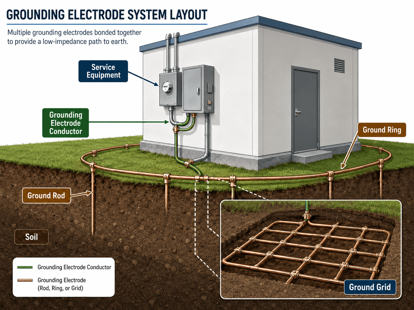
Grounding Electrodes, Ground Rings, and Ground Grids
Grounding electrodes connect the electrical installation to earth. Common electrode components include ground rods, metal underground water pipe where permitted, concrete-encased electrodes, ground rings, plates, and grids. Large facilities such as substations often use interconnected grounding grids to control touch and step voltage across a site.
Soil resistivity changes the result
Soil is not a perfect conductor. Moisture, temperature, mineral content, compaction, seasonal drying, frost depth, and electrode spacing can all change grounding performance. Two identical ground rod installations can behave very differently in wet clay versus dry rocky soil.
Electrodes support grounding, but they do not replace bonding
Ground rods and ground rings help connect a system to earth, but they are not a substitute for equipment grounding conductors, bonding jumpers, and proper source connections. In many practical faults, the metallic return path is more important for fast clearing than the resistance of a single rod.
Touch Voltage, Step Voltage, and Personnel Safety
Grounding is closely tied to shock hazard because people can be exposed to voltage differences during faults, lightning events, or equipment failures. Touch voltage occurs when a person contacts energized equipment while standing at a different potential. Step voltage occurs when voltage changes across the ground between a person’s feet.
| Safety concept | What it means | Grounding implication |
|---|---|---|
| Touch voltage | Voltage between a conductive object and the ground or surface a person is standing on. | Bonding and grounding grids help keep exposed metal and walking surfaces closer in potential. |
| Step voltage | Voltage difference across the ground between two points near a fault or electrode discharge. | Substation and utility grounding designs often focus on controlling surface gradients. |
| Clearing time | How long the fault remains energized before protection operates. | Lower impedance paths and coordinated protection reduce exposure duration. |
| Fault energy | The energy released during a fault, influenced by current magnitude and duration. | Grounding must work with overcurrent protection, relays, and equipment interrupting ratings. |
Senior Engineer Grounding Review Checklist
A grounding review should start with the purpose of the grounding system, then confirm that the physical installation supports that purpose. The checklist below is designed to catch the issues that a simple “ground rod installed” review can miss.
Identify the source and grounding method, trace the fault-current path back to the source, verify bonding continuity, review electrode connections, then confirm that protective devices can detect and clear the expected ground-fault condition.
| Grounding review check | What to look for | Why it matters |
|---|---|---|
| Grounding objective | Determine whether the system is designed for fault clearing, voltage stabilization, lightning, surge control, noise reduction, or personnel safety. | Different objectives can require different conductors, electrodes, protection settings, and inspection priorities. |
| Fault-current return path | Trace the metallic equipment grounding and bonding path back to the transformer, generator, inverter, or service source. | A ground fault must return to the source with enough current to operate protection. |
| Neutral-ground bond location | Confirm the main bonding jumper or system bonding jumper is installed at the correct source location. | Improper bonds can create objectionable current on equipment grounding paths and expose metal parts to unsafe conditions. |
| Bonding continuity | Check raceways, equipment enclosures, doors, skids, cable trays, transformers, generators, disconnects, and flexible connections. | A missing jumper or loose connection can break the safety path even when a ground electrode exists. |
| Electrode condition | Inspect rods, rings, grids, clamps, exothermic welds, corrosion, mechanical damage, and burial conditions. | Electrode degradation can reduce grounding effectiveness and create unreliable test results. |
| Protective device coordination | Confirm breaker, fuse, relay, or ground-fault protection settings are compatible with the grounding method. | Grounding and protection must be designed together; neither system works alone. |
Grounding Tests and Field Verification
Field testing should match the question being asked. A ground resistance test evaluates the electrode system’s connection to earth, while continuity checks help verify whether equipment, raceways, bonding jumpers, and grounding conductors are actually connected as intended.
Ground resistance testing
Ground resistance testing is useful when the performance of the grounding electrode system matters, such as for service grounding, lightning protection, substations, communications systems, and certain owner specifications. The result is influenced by soil resistivity, electrode geometry, moisture, spacing, and test method.
Continuity testing
Continuity testing verifies the conductive path between equipment, enclosures, bonding jumpers, and grounding conductors. This is a different question than electrode resistance, and it is often the more important field check for equipment fault clearing.
A low electrode resistance reading does not automatically prove that equipment bonding is intact. A grounding system can have an acceptable earth connection and still have a broken or high-impedance fault-current path inside the installation.
Engineering Judgment and Field Reality
Field grounding problems are often connection problems, not theory problems. A design may look correct on a one-line diagram, but corrosion, paint, loose hardware, missing bonding bushings, damaged conductors, or poor terminations can interrupt the real fault-current path.
Engineers also need to distinguish between grounding for power-frequency faults and grounding for transients. Lightning, switching surges, electronic noise, and ground faults are related to grounding, but they do not behave the same way. A long conductor that works acceptably at 60 Hz may perform poorly for fast transients because inductance becomes important.
Generators, inverters, and separately derived systems
Generators, transformers, UPS systems, and inverter-based sources can change where the neutral-to-ground bond belongs. Transfer switch configuration, source type, and separately derived system rules affect whether the grounding path remains effective during alternate-source operation.
A low ground resistance test number does not automatically prove the equipment grounding path is safe. Continuity, bonding, conductor routing, source connection, and protective device operation still need to be reviewed.
When This Breaks Down
Simplified grounding diagrams are useful for learning, but they can break down when applied to complex systems. Real power systems may have multiple sources, separately derived systems, generators, inverters, transfer switches, transformers, parallel paths, or sensitive loads that change how grounding and bonding should be reviewed.
- Multiple sources: Utility service, standby generators, UPS systems, and solar inverters can create different grounding and bonding requirements depending on how they are connected.
- High soil resistivity: Dry, rocky, frozen, or sandy soil can make electrode performance much worse than expected.
- Long grounding conductors: Long paths can add impedance and inductance, especially for surge and lightning events.
- Corroded or painted connections: A conductor may appear connected visually while the electrical connection is poor.
- Incorrect isolated grounds: Isolated grounding can reduce noise in some cases, but it must not remove the required safety grounding path.
Common Grounding Mistakes and Practical Checks
Many grounding errors come from treating all green wires, rods, neutrals, and bonds as if they perform the same job. In power systems, the details matter because grounding affects both normal system behavior and fault response.
| Common mistake | Why it is a problem | Practical check |
|---|---|---|
| Assuming a ground rod trips the breaker | Soil resistance is usually too high to carry enough current for reliable overcurrent operation. | Trace the equipment grounding conductor and bonding path back to the source. |
| Confusing neutral and ground | Neutral carries normal return current; equipment grounding paths should not carry normal load current. | Verify neutral-ground bonding occurs only where intended for the system configuration. |
| Missing bonding jumpers | Metal raceways, doors, trays, skids, and enclosures may not remain at the same potential during a fault. | Inspect across flexible connections, painted joints, removable doors, and equipment sections. |
| Ignoring grounding electrode spacing | Electrodes placed too close together may not improve performance as much as expected. | Review electrode layout, soil conditions, and applicable design criteria. |
| Using isolated grounding incorrectly | Noise-control grounding can be misunderstood and accidentally weaken the safety grounding path. | Confirm isolated grounds remain code-compliant and still bond properly at the correct point. |
The most dangerous misunderstanding is thinking earth is the main fault-current return path. For most building and equipment faults, the effective return path is the bonded equipment grounding system back to the source.
Codes, Standards, and Practical Design References
Grounding is a code- and safety-sensitive subject, so educational diagrams should be paired with recognized references. For U.S. electrical installations, grounding and bonding are closely associated with NEC Article 250, while larger power system and substation applications may also involve IEEE-style grounding studies, owner standards, and utility requirements.
- NFPA grounding and bonding overview: NFPA explanation of grounding and bonding basics explains why grounding and bonding are different concepts and how Article 250 fits into electrical safety.
- Project-specific criteria: Equipment voltage, source configuration, utility requirements, authority having jurisdiction, owner standards, and site conditions can control final grounding details.
- Engineering use: Engineers use these references to confirm conductor sizing, bonding requirements, electrode systems, ground-fault protection, and inspection expectations for the specific installation.
Frequently Asked Questions
Grounding techniques are methods used to connect electrical systems, equipment, and conductive parts to earth or to a common reference point so voltage is stabilized, fault current has a safe return path, and protective devices can operate correctly.
Grounding connects a system or conductor to earth or a reference point, while bonding connects conductive parts together so they remain at nearly the same potential. In practical electrical safety, both are needed because bonding helps create the low-impedance path that allows faults to clear.
A ground rod by itself usually does not provide enough fault current to reliably trip a breaker. Breakers and fuses normally depend on an effective equipment grounding conductor and bonding path back to the source, not only current flowing through soil.
The best grounding method depends on the system voltage, source configuration, fault-current level, equipment type, continuity requirements, soil conditions, and applicable code requirements. A residence, industrial plant, generator, substation, and data center may all use different grounding approaches.
Field checks typically include verifying bonding continuity, inspecting conductor and clamp condition, confirming the neutral-ground bond location, checking electrode connections, reviewing corrosion or mechanical damage, and performing ground resistance or continuity testing where required by the project.
Summary and Next Steps
Grounding techniques are the practical methods used to stabilize electrical systems, connect equipment to a safe reference, control voltage differences, and support protective device operation during faults. The most important idea is that grounding is a system, not a single rod or conductor.
Good grounding requires coordinated system grounding, bonding, equipment grounding conductors, electrodes, protection settings, and field verification. Engineers should review the intended function, trace the fault-current path, inspect bonding continuity, and account for soil, corrosion, multiple sources, and real installation conditions.
Where to go next
Continue your learning path with related Turn2Engineering power systems resources.
-
Overcurrent Protection
Learn how breakers, fuses, and protective devices respond when grounding and bonding create a sufficient fault-current path.
-
Protective Relays
Explore how relay systems detect faults and isolate equipment in larger power systems.
-
Switchgear
Understand the equipment used to switch, protect, and isolate electrical circuits during normal operation and faults.