Key Takeaways
- Core idea: A power system is a connected network of equipment that generates, transforms, transmits, distributes, protects, controls, measures, and uses electrical energy.
- Engineering use: Engineers study power system components to understand load flow, voltage control, fault isolation, equipment ratings, reliability, maintenance access, and system safety.
- What controls it: Voltage level, power demand, fault current, insulation strength, protection coordination, grounding, equipment ratings, and operating reliability shape component selection.
- Practical check: A complete power system is not just generation, transmission, and distribution; it also depends on protection, control, metering, communication, grounding, and maintenance isolation.
Table of Contents
Introduction
Power system components are the electrical equipment and control devices used to produce, transform, move, distribute, protect, measure, and consume electric power. The main components include generators, transformers, transmission lines, substations, circuit breakers, relays, distribution feeders, meters, grounding equipment, and loads. Understanding how these pieces connect is the foundation of power systems engineering.
Power System Components Diagram
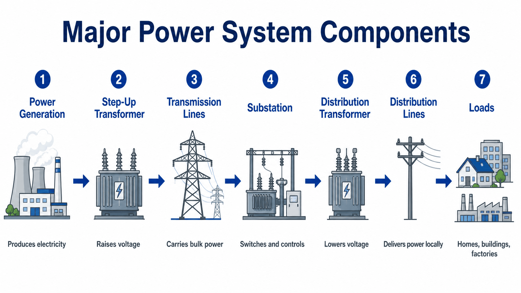
Follow the voltage and control path first. Power is not simply sent from a plant to a building; it is transformed, switched, protected, monitored, and stepped down through several stages before it becomes usable power at the load.
What Are Power System Components?
Power system components are the physical and digital parts of an electric power network. Some components carry energy directly, such as conductors, transformers, busbars, feeders, and cables. Other components protect or control the system, such as relays, circuit breakers, fuses, meters, communication devices, and supervisory control equipment.
In practice, engineers often separate components into primary equipment and secondary systems. Primary equipment handles voltage, current, and power flow. Secondary systems measure, protect, automate, and supervise that equipment. A one-line diagram may make a power system look simple, but the real engineering depends on how these primary and secondary components coordinate during normal operation, maintenance, switching events, and faults.
Power System Components and Their Functions
The best way to learn power system components is to connect each piece of equipment to its function. A component is the device itself; the function is the job it performs in the electrical network. This distinction helps when reading one-line diagrams, reviewing equipment lists, or learning how generation, transmission, distribution, and protection work together.
| Component | Main function | Typical engineering concern |
|---|---|---|
| Generator or inverter | Produces or injects electrical power into the system. | Real power output, voltage control, frequency behavior, synchronization, and protection. |
| Transformer | Raises or lowers voltage so power can be transmitted efficiently and used safely. | Voltage ratio, loading, impedance, cooling, insulation, losses, and fault withstand rating. |
| Transmission line | Moves bulk electrical power over long distances at high voltage. | Thermal rating, voltage drop, stability, clearances, insulation coordination, and line protection. |
| Substation | Switches, transforms, protects, measures, and controls power flow between circuits. | Bus configuration, breaker duty, transformer sizing, grounding, relay zones, and maintainability. |
| Distribution feeder | Delivers power locally from a substation to neighborhoods, buildings, or industrial loads. | Voltage regulation, load growth, fault coordination, conductor ampacity, and service reliability. |
| Circuit breaker, fuse, or recloser | Interrupts current during faults or abnormal conditions. | Interrupting rating, speed, selectivity, reclosing logic, and coordination with other devices. |
| Protective relay | Detects abnormal electrical conditions and commands protective action. | Settings, inputs from CTs/PTs, coordination, communication, and correct protection zone coverage. |
| Metering and SCADA equipment | Measures energy, monitors status, records events, and supports remote operation. | Accuracy, communication reliability, cybersecurity, data quality, and operator visibility. |
| Load | Consumes electrical power through motors, lighting, HVAC, electronics, process equipment, or appliances. | Demand, power factor, harmonics, starting current, voltage sensitivity, and reliability needs. |
If a diagram only shows generation, transmission, distribution, and load, it is missing many of the parts that make the system safe and operable. Protection, metering, grounding, communication, switching, and control equipment are part of how the system actually works.
Power System Component Categories
Grouping components by category makes the system easier to understand. A power system is not one continuous piece of equipment; it is a collection of source components, voltage-conversion components, delivery components, switching devices, protection devices, monitoring equipment, grounding systems, and loads.
| Category | Examples | Purpose in the system |
|---|---|---|
| Source components | Generators, solar inverters, wind turbine generators, battery inverters | Produce or inject real and reactive power into the electrical network. |
| Transformation components | Step-up transformers, step-down transformers, distribution transformers, tap changers | Change voltage levels for transmission, distribution, utilization, and voltage regulation. |
| Delivery components | Transmission lines, distribution feeders, busbars, cables, conductors | Carry electrical energy between sources, substations, and loads. |
| Switching components | Circuit breakers, disconnect switches, load break switches, reclosers, switchgear | Connect, disconnect, isolate, or interrupt circuits during operation and faults. |
| Protection components | Relays, fuses, CTs, PTs, surge arresters, trip circuits | Detect abnormal conditions and isolate faulted equipment before damage spreads. |
| Control and monitoring components | SCADA, RTUs, meters, sensors, IEDs, communication links | Measure system status, report alarms, record events, and support remote operation. |
| Grounding and safety components | Ground grids, bonding conductors, neutral grounding equipment, surge protection | Support fault clearing, voltage reference, equipment protection, and personnel safety. |
| Load components | Motors, lighting, HVAC, appliances, data centers, industrial process equipment | Consume electrical energy and determine much of the demand, voltage drop, and power quality behavior. |
How Power Flows From Generation to Load
Power system components are easiest to understand by following the energy path. Electricity is produced at a generating source, stepped up to a higher voltage for efficient transmission, carried across the network, switched and transformed in substations, distributed at lower voltage, and finally delivered through service equipment to end-use loads.
Generation and step-up transformation
Generators, renewable inverters, or battery energy storage inverters inject power into the system. A generator step-up transformer commonly raises voltage so the same power can be transmitted with lower current. Lower current reduces resistive losses and helps keep conductor size, voltage drop, and heat within practical limits.
Transmission, substations, and step-down transformation
Transmission lines carry bulk power between regions, plants, and substations. Substations then provide switching, protection, voltage transformation, metering, and control. A transmission substation may connect multiple high-voltage lines, while a distribution substation steps voltage down to feeder levels for local delivery.
Distribution and utilization
Distribution feeders move power through local circuits. Reclosers, fuses, switches, capacitor banks, regulators, and distribution transformers help control voltage, isolate faults, and serve customers. The final load may be a home, factory, data center, motor control center, EV charger, lighting panel, or industrial process.
This basic relationship helps explain why high voltage is useful for transmission. For a given amount of power, increasing voltage allows current to decrease. Because conductor heating losses are related to current, voltage transformation is one of the most important functions in the entire power system.
A common learning path is generator voltage, step-up transformer voltage, transmission voltage, substation step-down voltage, distribution feeder voltage, distribution transformer secondary voltage, and then utilization voltage at the load.
How to Read Power System Components on a One-Line Diagram
A one-line diagram is a simplified drawing that shows how major power system components connect electrically. Instead of drawing every conductor in a three-phase system, it uses one line to represent the circuit path. This makes it easier to see sources, transformers, buses, breakers, feeders, protection zones, and loads.
| One-line item | What it usually represents | What to check |
|---|---|---|
| Source symbol | Generator, utility source, inverter, or other supply point. | Voltage, available fault current, grounding method, and source operating mode. |
| Transformer symbol | Voltage conversion point between two system voltage levels. | kVA/MVA rating, voltage ratio, impedance, cooling, tap settings, and protection. |
| Busbar | Common electrical node where multiple circuits connect. | Bus rating, short-circuit bracing, configuration, maintenance isolation, and protection zone. |
| Breaker or fuse | Device that interrupts load current, fault current, or both depending on type and rating. | Continuous rating, interrupting rating, trip settings, and upstream/downstream coordination. |
| Disconnect switch | Visible isolation point for maintenance or switching. | Whether it is rated for load break, where it isolates, and whether it can be operated safely. |
| CT/PT symbols | Instrument transformers feeding relays, meters, and control equipment. | Ratio, accuracy class, polarity, grounding, wiring, and relay/meter connections. |
| Feeder | Outgoing circuit serving downstream equipment or loads. | Load current, conductor ampacity, voltage drop, protection, and load growth. |
| Load symbol | Motor, panel, building, process equipment, or aggregated load. | Demand, starting current, power factor, harmonics, and required reliability. |
When reviewing a one-line diagram, do not only trace where power flows. Also trace where faults are measured, where breakers trip, where equipment can be isolated, how voltage changes, and which loads are lost if each device opens.
Generation and Transmission Components
Generation and transmission equipment form the front end of many power systems. These components are designed for bulk energy production, high power transfer, voltage control, and system reliability. They are also where system stability, synchronization, and high fault current levels become major engineering concerns.
Generation components
Generation components may include generators, turbines, prime movers, excitation systems, generator circuit breakers, generator step-up transformers, switchgear, plant auxiliary transformers, protective relays, and synchronization equipment. In renewable systems, the source may include PV arrays, wind turbine generators, inverters, collector feeders, inverter step-up transformers, and plant-level controls.
Transmission components
Transmission components include towers or poles, phase conductors, shield wires, insulators, spacers, dampers, line terminals, high-voltage circuit breakers, disconnect switches, line relays, communication channels, and substation buswork. Although transmission lines look like simple wires from a distance, their design depends on thermal rating, clearances, insulation strength, lightning performance, right-of-way constraints, and stability limits.
A transmission circuit is not judged only by conductor size. Protection zones, breaker interrupting duty, line clearances, switching procedures, communications, vegetation management, and substation terminations can control whether the circuit is reliable and maintainable.
Substation Components
Substations are the equipment-dense nodes of a power system. They connect circuits, change voltage levels, isolate faults, provide maintenance access, measure current and voltage, and allow operators or control systems to manage power flow. Substations may serve transmission, subtransmission, distribution, generation interconnection, industrial, or facility-level roles.
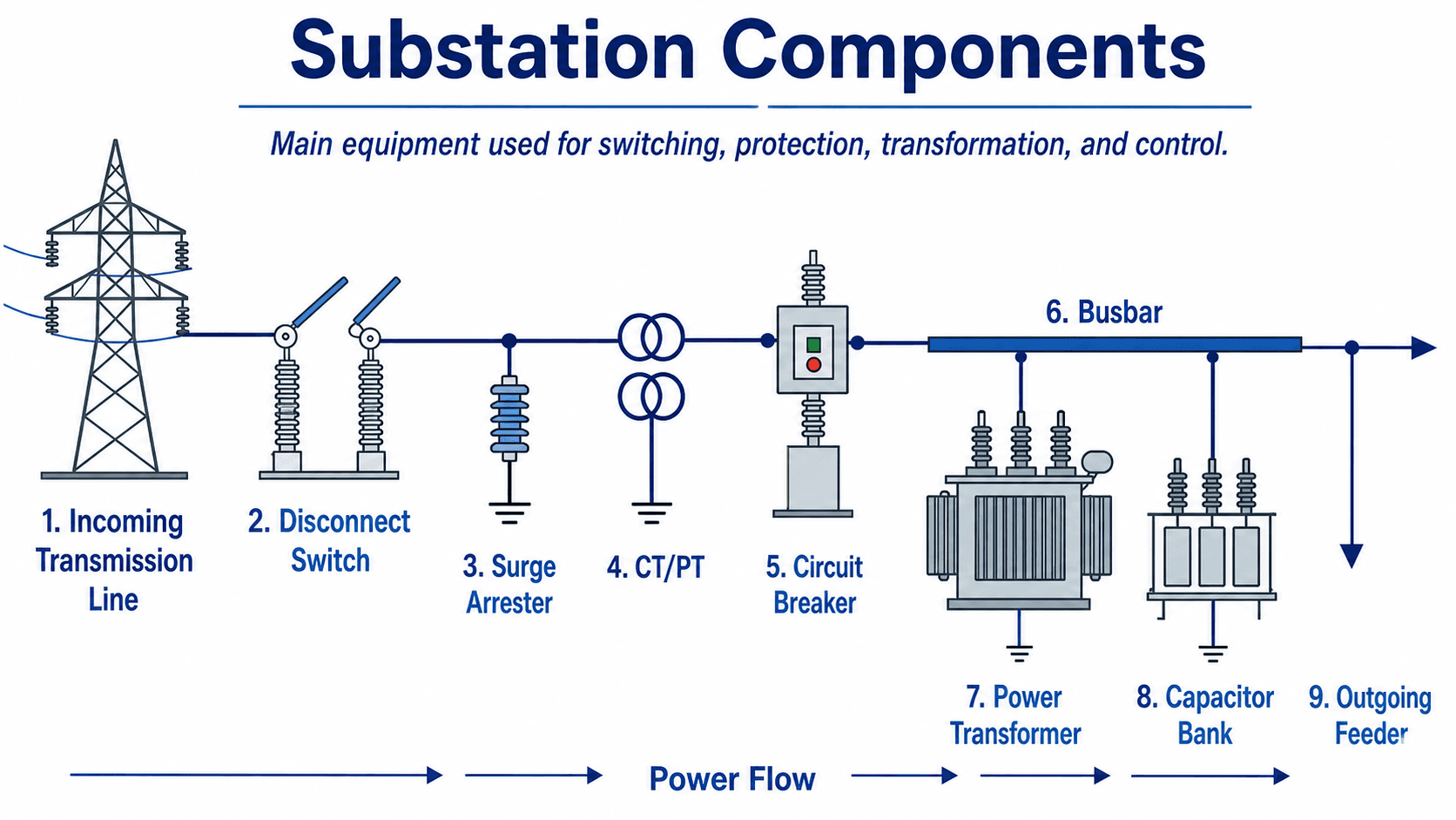
| Substation component | What it does | Practical note |
|---|---|---|
| Busbar | Provides a common conductive connection point for incoming and outgoing circuits. | Bus arrangement affects reliability, maintenance flexibility, and outage exposure. |
| Circuit breaker | Interrupts load current and fault current when commanded by controls or relays. | Breaker interrupting rating must exceed available fault current with adequate margin. |
| Disconnect switch | Provides visible isolation for equipment, lines, or transformer maintenance. | Disconnects are usually not intended to interrupt high fault current. |
| Current transformer | Scales current to safer levels for relays, meters, and monitoring devices. | CT ratio, accuracy, saturation, and polarity matter for protection performance. |
| Potential or voltage transformer | Scales voltage to usable levels for measurement, relays, synchronizing, and controls. | Incorrect voltage reference can affect metering, relay logic, and voltage control. |
| Surge arrester | Limits transient overvoltages from lightning or switching events. | Placement and insulation coordination affect equipment protection. |
| Power transformer | Transfers power between voltage levels. | Loading, cooling, impedance, tap settings, protection, and oil condition are common design and maintenance concerns. |
| Capacitor bank | Provides reactive power support and helps improve voltage profile or power factor. | Switching transients, harmonics, and protection coordination must be checked. |
Distribution System Components
Distribution system components deliver electrical power from substations to end users. These components usually operate at lower voltage than transmission equipment, but they are highly exposed to load changes, weather, vegetation, customer additions, voltage drop, outage restoration, and maintenance constraints.
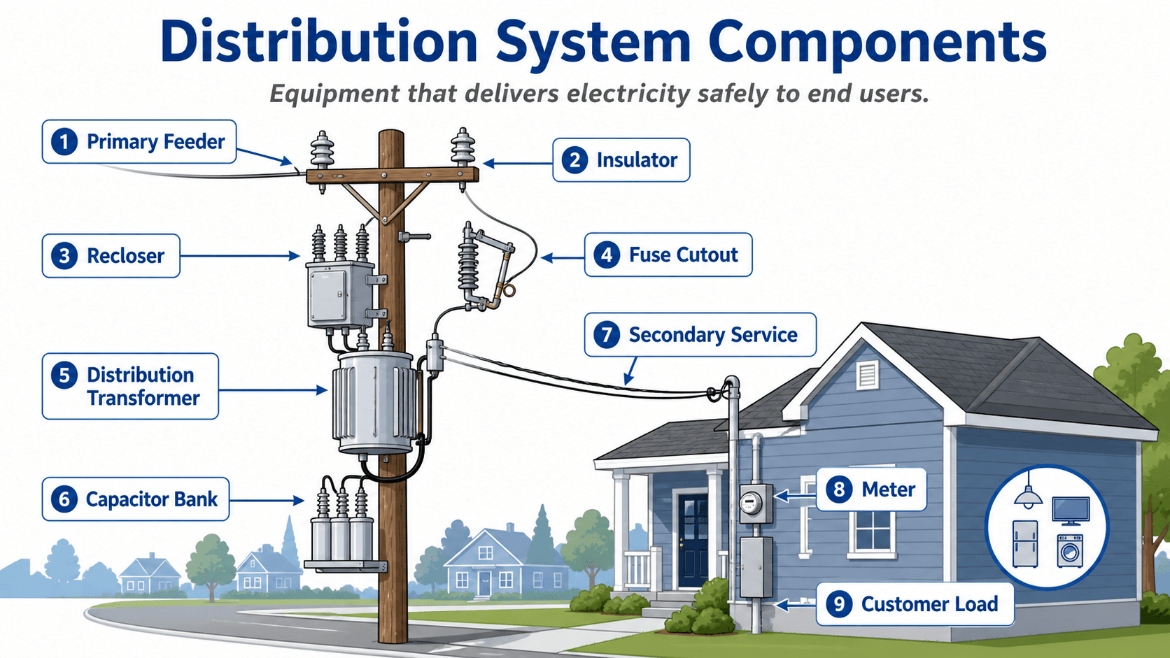
Primary distribution
Primary distribution feeders carry medium-voltage power from a distribution substation into a service area. These circuits may include overhead lines, underground cables, reclosers, sectionalizers, fuse cutouts, voltage regulators, capacitor banks, and switches. Feeder design is influenced by load density, distance, voltage drop, fault current, reliability targets, and future load growth.
Secondary distribution and customer service
Distribution transformers step voltage down to the level used by customer equipment. Secondary service conductors, meters, service disconnects, panels, and customer loads complete the delivery path. At this level, load diversity, transformer loading, service conductor ampacity, voltage drop, grounding, and power quality become major practical concerns.
Protection and Control Components
Protection and control components keep abnormal conditions from becoming equipment failures, outages, or safety hazards. These devices do not normally carry the main power flow in the same way as a transformer or feeder, but they determine how quickly and selectively the system responds when something goes wrong.
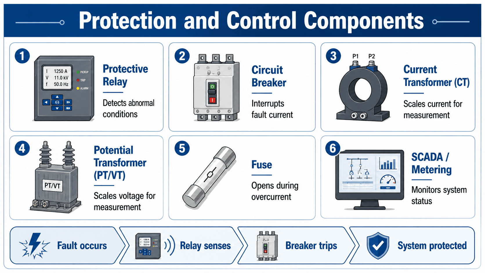
The basic fault response sequence
A typical protection sequence is: fault occurs, CTs and PTs sense abnormal current or voltage, the relay determines whether the condition is inside its protection zone, the breaker trips, and the faulted section is isolated. The goal is not just speed; the goal is selective isolation so healthy parts of the system remain energized where possible.
Follow the fault: distribution feeder example
If a tree branch contacts an overhead distribution feeder, current may rise quickly. A recloser or relay senses the abnormal current, opens the circuit, and may attempt to reclose after a short delay. If the fault was temporary, service can be restored automatically. If the fault remains, the device locks out or a downstream fuse isolates the affected lateral.
Control, metering, and communication
Modern power systems also depend on SCADA, RTUs, intelligent electronic devices, meters, alarms, communication links, and control logic. These systems help operators monitor breaker status, voltage, current, power flow, transformer loading, relay events, capacitor bank status, and feeder performance.
A protective device should not be reviewed alone. Engineers check the full chain: CT/PT selection, relay logic, DC control power, trip circuit continuity, breaker rating, communication dependency, and coordination with upstream and downstream devices.
Common Component Confusions
Many power system components look similar in diagrams or are mentioned together in textbooks, but they do different jobs. Understanding these differences helps prevent mistakes when reading one-line diagrams, studying substation layouts, or reviewing electrical equipment lists.
| Common confusion | Correct understanding | Why it matters |
|---|---|---|
| Circuit breaker vs. disconnect switch | A breaker interrupts load and fault current when properly rated; a disconnect provides visible isolation and is often operated de-energized. | Using a disconnect like a breaker can create unsafe switching conditions. |
| CT vs. PT/VT | A CT scales current; a PT or VT scales voltage. | Relays and meters need the correct current and voltage inputs to operate accurately. |
| Substation vs. transformer | A transformer is one component; a substation is a facility or equipment group that may include transformers, breakers, busbars, relays, and controls. | Substation performance depends on more than the transformer rating. |
| Transmission vs. distribution | Transmission moves bulk power at high voltage; distribution delivers power locally at lower voltage. | The equipment ratings, protection schemes, reliability goals, and operating practices are different. |
| Fuse vs. relay | A fuse melts open during overcurrent; a relay detects abnormal conditions and commands a breaker or other device to operate. | Relay-based protection can be more adjustable and selective, while fuses are simpler but less flexible. |
| Grounding vs. neutral | Grounding provides reference and fault-current paths; a neutral may carry normal return current depending on the system. | Confusing the two can lead to unsafe wiring, incorrect protection behavior, and poor fault clearing. |
Key Factors That Control Component Selection
Power system components are selected by function, voltage level, current rating, fault duty, environment, protection requirements, operating philosophy, maintenance access, and reliability goals. Two systems may show similar symbols on a one-line diagram but require very different equipment ratings and control schemes.
| Factor | Why it matters | Engineering implication |
|---|---|---|
| Voltage level | Controls insulation, clearances, transformer ratios, arresters, switchgear class, and worker safety practices. | Equipment must be rated for normal voltage and expected overvoltage conditions. |
| Load current | Determines conductor ampacity, transformer loading, breaker continuous rating, and thermal performance. | Underrated equipment overheats; oversized equipment may increase cost and reduce protection sensitivity. |
| Fault current | Controls breaker interrupting rating, fuse duty, bus bracing, transformer withstand, and arc energy potential. | Short-circuit studies are needed before final protection and equipment ratings are selected. |
| Protection coordination | Determines which device should trip first and how much of the system remains energized during a fault. | Relay, fuse, recloser, and breaker settings must coordinate across the system. |
| Reliability requirement | Critical loads may require redundancy, alternate feeds, transfer schemes, or sectionalizing. | Higher reliability usually increases equipment count, complexity, space, and maintenance requirements. |
| Environment | Temperature, contamination, elevation, lightning exposure, flooding, corrosion, and wildlife can change equipment performance. | Outdoor and harsh-environment equipment may need different insulation, enclosures, clearances, and maintenance plans. |
What Component Controls the Design?
In real projects, the controlling component is the one that limits capacity, reliability, safety, or maintainability. It is not always the most expensive or most visible piece of equipment. A small control-power issue, weak protection setting, undersized breaker, overloaded transformer, or poor isolation arrangement can control the practical performance of the whole system.
| Situation | Component likely to control | Reason |
|---|---|---|
| Long-distance power transfer | Transmission conductor, voltage level, transformer impedance, or stability limit | Losses, voltage drop, thermal rating, and stability can limit how much power can be moved. |
| High available fault current | Breaker, switchgear, bus bracing, fuse, or transformer withstand rating | Equipment must safely withstand and interrupt fault current. |
| Poor voltage profile | Transformer tap changer, voltage regulator, capacitor bank, feeder length, or conductor size | Voltage can fall outside acceptable limits even when the circuit is energized and below thermal ampacity. |
| Critical loads | Transfer switch, redundant feeder, UPS, generator, relay scheme, or bus configuration | Reliability and outage duration may control the equipment arrangement more than basic load current. |
| Renewable interconnection | Inverter controls, transformer, relay settings, metering, communication, or utility interconnection device | Reverse power flow, anti-islanding, voltage ride-through, and protection coordination can control the design. |
| Maintenance outage planning | Disconnects, bypass switches, spare transformer capacity, bus arrangement, or switching procedure | Equipment that cannot be isolated safely can force larger outages than expected. |
Power System Component Review Checklist
A practical component review starts with the one-line diagram, then checks whether each piece of equipment has a clear purpose, a suitable rating, and a coordinated role in normal operation and fault response. The checklist below is a useful way to review a power system at a conceptual level before detailed studies are finalized.
Start at the source, follow the power path to the load, identify every voltage transformation, locate every switching point, define every protection zone, confirm how current and voltage are measured, and then verify that grounding, control power, metering, and maintenance isolation are not missing from the design.
| Review item | What to look for | Why it matters |
|---|---|---|
| Power path | Clear source-to-load path through generators, transformers, lines, buses, feeders, and service equipment. | Unclear power paths lead to missed ratings, missed isolation points, and poor troubleshooting. |
| Voltage transitions | Every step-up and step-down transformer, tap range, nominal voltage, and operating voltage limit. | Voltage mismatch can damage equipment, create poor regulation, or prevent proper interconnection. |
| Fault interruption | Breakers, fuses, reclosers, and switchgear rated for available fault current. | Protective devices must interrupt faults safely, not just carry normal load current. |
| Protection zones | Relay, CT, PT, breaker, fuse, and recloser coverage for each generator, transformer, bus, line, and feeder. | Gaps or overlaps in protection can cause nuisance trips or leave equipment exposed. |
| Grounding and surge protection | Ground grid, equipment bonding, neutral grounding method, surge arresters, and lightning protection where needed. | Grounding and surge control affect personnel safety, fault clearing, insulation stress, and equipment damage risk. |
| Operations and maintenance | Disconnects, bypasses, visible isolation, access clearances, labeling, switching sequence, and spare capacity. | A system that works electrically may still be hard or unsafe to maintain if isolation and access are not planned. |
Example: Power Delivery to a Commercial Building
A practical example helps connect the component list to a real system. Consider a commercial building served from a utility distribution system. The building does not receive power directly from a generator; it receives power through a chain of transformation, switching, protection, metering, and distribution equipment.
Typical power path
Power may begin at a generating plant, renewable facility, or regional grid source. A transformer raises voltage for transmission. Transmission lines carry bulk power to a substation. The substation steps the voltage down and sends power through a distribution feeder. A pad-mounted or pole-mounted distribution transformer lowers voltage again for the building service. The meter records energy use, and switchgear or panelboards distribute power to HVAC equipment, lighting, elevators, receptacles, and process loads.
Engineering meaning
The building owner may only see the service transformer, meter, switchgear, and panels, but upstream transmission, substation, feeder, and protection components still control reliability and fault behavior. When engineers evaluate service capacity or power quality, they often need to understand both the customer-side equipment and the upstream utility system.
Modern Power System Components
Modern power systems increasingly include components that were less common in traditional centralized grids. Solar plants, wind farms, battery energy storage systems, microgrids, EV charging networks, smart meters, advanced inverters, and digital controls can change how power flows, how faults behave, and how voltage and frequency are supported.
Inverter-based resources
Solar PV, batteries, and many wind systems connect through power electronic inverters rather than conventional synchronous generators. Inverter controls affect voltage regulation, reactive power support, fault current contribution, ride-through behavior, and coordination with utility protection schemes.
Distributed generation and reverse power flow
Older distribution systems were often designed for one-way power flow from the substation to the customer. Distributed generation can send power back toward the feeder or substation, which may affect voltage regulation, fuse coordination, recloser behavior, transformer loading, metering, and interconnection protection.
Smart grid and monitoring components
Smart meters, sensors, automated switches, feeder automation, SCADA, distribution management systems, and communication networks help utilities and facility operators monitor the system in more detail. These components do not replace transformers, breakers, and conductors, but they make the system more observable and controllable.
Engineering Judgment and Field Reality
Textbook diagrams usually show idealized component blocks, but field systems are shaped by existing equipment, outage windows, space limitations, utility standards, weather exposure, spare parts, operations practices, and maintenance history. Engineers must understand both the electrical function of a component and the practical environment where it will operate.
The component that controls the design is not always the largest transformer or the longest line. A weak protection scheme, undersized breaker, inaccessible disconnect, poor grounding connection, overloaded distribution transformer, or missing control power source can become the limiting issue.
When This Breaks Down
A simple component list breaks down when the system must be designed, operated, protected, or maintained. Real power systems are dynamic networks, so equipment behavior changes under load changes, faults, switching events, lightning, reverse power flow, inverter operation, and abnormal voltage or frequency conditions.
- Fault conditions: Components that perform well under load may fail or become unsafe if interrupting ratings, withstand ratings, or relay settings are incorrect.
- Reverse power flow: Distributed generation and batteries can send power in directions that older distribution protection schemes were not designed for.
- Voltage regulation limits: Long feeders, high motor starting current, capacitor switching, or rapid solar output changes can create voltage issues even when equipment is properly connected.
- Maintenance switching: A one-line diagram may not show whether equipment can be isolated safely without interrupting critical loads.
- Measurement errors: Incorrect CT/PT ratios, polarity, grounding, or wiring can cause wrong metering values and incorrect relay operation.
Common Mistakes and Practical Checks
Many beginners understand the broad idea of generation, transmission, and distribution but miss the equipment that makes the system safe, selective, and maintainable. A strong understanding of power system components requires looking beyond the energy path and checking the supporting protection, control, metering, grounding, and operating systems.
- Confusing disconnect switches with breakers: Disconnects isolate equipment, while breakers are designed to interrupt load and fault current when properly rated.
- Treating CTs and PTs as minor accessories: Instrument transformers are essential for accurate protection, metering, and control signals.
- Ignoring grounding: Grounding affects fault clearing, equipment protection, touch potential, surge behavior, and personnel safety.
- Looking only at normal load current: Equipment must also be checked for fault current, switching duty, insulation stress, thermal limits, and short-time withstand.
- Forgetting operations: Components must be understandable, labeled, accessible, and maintainable for real operators and field crews.
Do not evaluate a power system by component names alone. The same symbol on a one-line diagram can represent equipment with very different voltage class, interrupting rating, insulation level, protection function, and maintenance requirements.
Engineering References and Design Guidance
Power system component selection depends on project requirements, utility interconnection rules, equipment standards, electrical codes, and system studies. Broad educational references are useful for understanding how the grid is organized, but final engineering decisions should be based on the specific system voltage, load, fault current, protection philosophy, and applicable project criteria.
- U.S. Department of Energy: Electricity Grid Backgrounder explains the major generation, transmission, substation, distribution, and grid-control concepts that support a high-level understanding of power system components.
- Project-specific criteria: Utility standards, owner specifications, interconnection agreements, equipment ratings, local code requirements, and facility reliability targets may control the final component arrangement.
- Engineering use: Engineers combine one-line diagrams, load studies, short-circuit studies, coordination studies, grounding reviews, voltage drop checks, and equipment data sheets to verify that the selected components work together.
Frequently Asked Questions
The main components of a power system include generators, transformers, transmission lines, substations, switchgear, circuit breakers, protective relays, distribution feeders, meters, grounding equipment, control systems, and electrical loads. Together, they produce electricity, move it over distance, control voltage, isolate faults, and deliver usable power to end users.
Power system components are the devices that perform specific functions in an electrical network. Generators produce power, transformers change voltage, lines and busbars carry power, breakers and fuses interrupt faults, relays detect abnormal conditions, meters measure energy, grounding equipment supports safety, and loads consume power.
A substation commonly includes power transformers, busbars, circuit breakers, disconnect switches, current transformers, voltage transformers, surge arresters, capacitor banks, relays, control panels, grounding systems, batteries, and SCADA equipment. The exact arrangement depends on voltage level, reliability requirements, protection philosophy, and system layout.
Transmission components move bulk power over long distances at high voltage, using equipment such as transmission towers, high-voltage conductors, substations, breakers, and protection systems. Distribution components deliver power locally at lower voltage through feeders, reclosers, fuse cutouts, voltage regulators, distribution transformers, service conductors, meters, and customer loads.
Summary and Next Steps
Power system components are the equipment and control devices that allow electrical energy to move from source to load. The major pieces include generation equipment, transformers, transmission lines, substations, distribution feeders, protection systems, control systems, metering, grounding, and loads.
The most important learning path is to follow the power flow while also checking protection, voltage transformation, switching, grounding, measurement, and maintenance access. A power system is not just a chain of wires and transformers; it is an engineered network that must operate safely during normal load, switching events, faults, and changing grid conditions.
Where to go next
Continue your learning path with related Turn2Engineering resources.
-
Power Generation
Learn how electrical energy is produced and prepared for delivery into the wider power network.
-
Power Transmission
Review how bulk electrical power moves over long distances using high-voltage transmission systems.
-
Distribution Lines
Explore how local distribution conductors, feeders, and service equipment deliver power to end users.