
Torque Calculator
Calculate torque, force, lever arm distance, or angle using the torque equation \( \tau = F r \sin(\theta) \).
Calculator is for informational purposes only. Terms and Conditions
Choose what to solve for
Select the unknown variable. The required known values update automatically.
Enter the known values
Use positive magnitudes. Direction can be selected in advanced options.
Visual Check
See how force, lever arm, angle, and perpendicular force component create torque.
Solution
Live result, quick checks, warnings, and full solution steps.
Quick checks
- Perpendicular force—
Show solution steps See the equation, substitutions, conversions, assumptions, and result path
- Enter values to see the full solution steps and checks.
Source, Standards, and Assumptions
Calculation basis, constants, assumptions, and limitations.
This calculator uses the standard torque relationship \( \tau = F r \sin(\theta) \). It is an educational calculation, not a fastener preload or code-compliance design tool.
- Force, lever arm, and angle are treated as idealized static quantities.
- Standard unit conversion constants are used internally.
- Bolt preload, friction, thread pitch, lubrication, impact loading, and material limits are not included.
On this page
Calculator Guide
How to Use the Torque Calculator
The Torque Calculator above helps calculate torque from force, lever arm length, and angle. It also supports motor torque from power and RPM, torque unit conversion, and applied wrench or breaker bar torque estimates.
Torque is the rotational effect of a force about a pivot, shaft, axle, or fastener. The key idea is that force alone does not determine torque. The distance from the pivot and the angle of the force are just as important. A force applied perpendicular to a lever arm creates the most torque, while a force applied along the lever arm creates little or no torque.
Quick Answer
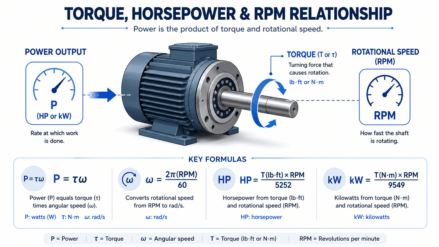
To calculate torque from force and distance, use \( \tau = rF\sin(\theta) \). Enter the applied force \( F \), lever arm length \( r \), and angle \( \theta \) between the force and lever arm. If the force is perpendicular, \( \sin(90^\circ) = 1 \), so torque simplifies to \( \tau = rF \). For motor torque, use \( P = \tau\omega \), where \( \omega = 2\pi RPM / 60 \).
Do not use this calculator when…
Do not use this calculator as a final fastener tightening specification, bolt preload calculation, shaft design, gearbox rating, lifting device design, or safety-critical equipment selection. It is useful for education, estimating, homework checks, and preliminary engineering review, but final design should use manufacturer data, equipment ratings, applicable standards, and professional judgment.
Inputs and Outputs Used by the Calculator
The calculator changes inputs based on the selected mode. Basic torque problems require force, lever arm, and angle. Motor and shaft problems use power and RPM. Conversion mode only needs a torque value and source/target units.
| Type | Value | What It Means | Common Unit |
|---|---|---|---|
| Input | Force | The push, pull, load, or applied effort creating rotation. | N, lbf, kgf |
| Input | Lever arm length | Distance from the pivot, shaft center, or fastener centerline to where the force is applied. | m, ft, in |
| Input | Angle | The angle between the force vector and lever arm. | degrees, radians |
| Input | Power | Mechanical shaft power for motors, engines, pumps, fans, and rotating machinery. | W, kW, hp |
| Input | Rotational speed | How fast the shaft or rotating body spins. | RPM |
| Output | Torque | The rotational moment about a pivot, shaft, axle, or fastener. | N·m, lb·ft, lb·in |
| Output | Force, lever arm, angle, power, or RPM | Alternate unknowns solved by rearranging the torque or power equation. | Depends on solve mode |
Formula Used by the Calculator
The calculator uses standard mechanics relationships for rotational moment and shaft power. The force-distance mode reports torque magnitude, not signed clockwise or counterclockwise direction.
Main Torque Formula
Use this equation when a force is applied at a known distance from a pivot and at a known angle to the lever arm.
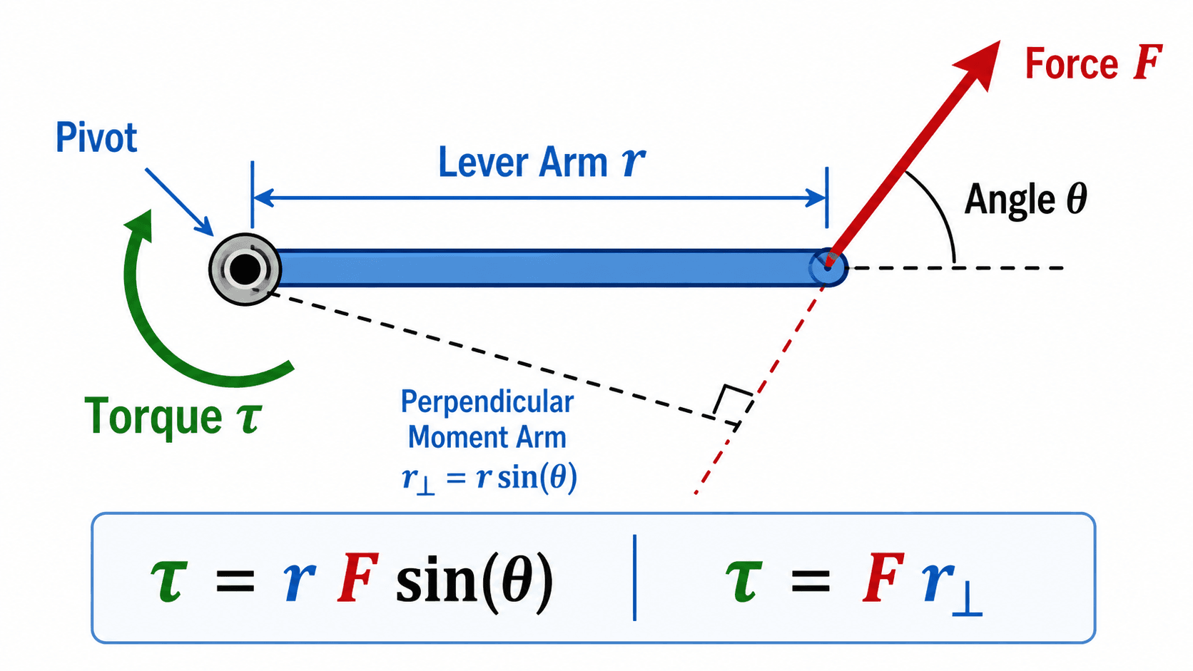
Perpendicular Moment Arm Form
This form explains why the perpendicular distance to the force line of action controls torque.
Rearranged Torque Formulas
These forms are used when solving for force, lever arm length, or angle instead of torque.
Power, Torque, and RPM
Use this relationship for motors, engines, shafts, pumps, fans, and other rotating equipment.
Common Motor Shortcuts
These shortcuts are unit-specific. Use torque in lb·ft for horsepower and torque in N·m for kilowatts.
Why the formula matters
The angle term is the part most users miss. A longer lever arm only creates maximum torque when the applied force is perpendicular to the lever arm. If the force is angled, only the perpendicular component contributes to rotation.
What the Variables Mean
A correct torque calculation depends on entering each variable the right way. The most common mistake is measuring the full handle length but applying the force at an angle, which means the effective moment arm is shorter than the visible lever length.
| Symbol | Meaning | How to Enter It |
|---|---|---|
| \( \tau \) | Torque or moment about a pivot or axis. | Enter as N·m, lb·ft, lb·in, kgf·m, or another supported torque unit. |
| \( r \) | Lever arm length. | Measure from the pivot, shaft center, or fastener centerline to the point where force is applied. |
| \( F \) | Applied force magnitude. | Use a force unit such as N or lbf. Do not enter mass unless it has been converted to force. |
| \( \theta \) | Angle between the force and lever arm. | Use 90° for a perpendicular pull. Use 0° or 180° only when the force acts along the lever arm. |
| \( r_{\perp} \) | Perpendicular moment arm. | The effective distance that actually creates torque. |
| \( P \) | Mechanical power. | Use shaft output power for motor and drivetrain calculations when available. |
| \( \omega \) | Angular speed. | The calculator converts RPM to rad/s using \( \omega = 2\pi RPM / 60 \). |
How to Use the Calculator
The calculator is built around the most common torque workflows. Choose the mode that matches the information you know, then review the units and quick checks before using the result.
Choose the calculation mode
Select Force × Lever Arm for physics and statics problems, Power, Torque & RPM for rotating machinery, Torque Unit Converter for unit conversion, or Wrench / Breaker Bar Torque for applied hand-tool torque.
Select the unknown
Depending on the selected mode, the calculator can solve for torque, force, lever arm length, angle, power, or RPM.
Enter geometry and units carefully
For force and wrench problems, measure distance from the pivot or fastener centerline. Then enter the angle between the force direction and the lever arm.
Review result meaning
Compare the result with equivalent units, maximum torque at 90°, practical ranges, and any warning shown by the calculator.
How to Interpret the Result
Torque is application-dependent. A value that is small for an industrial shaft may be large for a small fastener, hinge, or hand tool. The table below helps interpret the result before using it.
| Result Pattern | What It May Mean | What to Check Next |
|---|---|---|
| Zero or near-zero torque | The force may be acting along the lever arm, or force/distance may be zero. | Check whether the angle is close to 0° or 180°. |
| Moderate torque | The result may be reasonable for hand tools, hinges, classroom mechanics, and small shafts. | Compare equivalent N·m, lb·ft, and lb·in values. |
| High hand-tool torque | The result may require rated sockets, breaker bars, torque multipliers, or safer tooling. | Verify tool rating, fastener specification, and body position before applying load. |
| High motor torque | The result may imply high shaft load, gearbox load, starting load, or thermal demand. | Check continuous torque, peak torque, speed-torque curve, efficiency, and duty cycle. |
| Unexpected motor result | Power may be electrical input power instead of usable shaft output power. | Confirm whether the power value is input, output, rated, peak, or continuous. |
What to do with the result
Use the torque result as a magnitude check. For statics and physics problems, assign clockwise or counterclockwise direction separately using your sign convention. For machinery, compare the result with shaft, coupling, bearing, gearbox, motor, and fastener ratings before using it for design.
What changes the result most?
Force and lever arm length change torque directly, but angle is the easiest input to overlook. A 100 N force on a 0.5 m lever arm creates 50 N·m at 90°, about 35.4 N·m at 45°, and 0 N·m at 0°. The same force and distance can therefore produce very different torque depending on direction.
Quick sanity check
For a perpendicular force, torque should equal force times distance. If you apply 100 N at 0.5 m, the maximum possible torque is \( 100 \times 0.5 = 50 \, N\cdot m \). If your result is much different, check the angle and unit selectors first.
Input Quality Checklist
Before relying on the output, review the inputs below. Most torque errors come from measuring the wrong distance, using the wrong angle, or mixing unit systems.
Force Is Actually Force
Enter force, not mass. Pounds of body weight are commonly treated as pounds-force, but kilograms must be converted to force if used as a load.
Distance Starts at the Pivot
Measure from the pivot, shaft center, or fastener centerline to the point where the force is applied.
Angle Uses the Correct Reference
Use the angle between the force vector and lever arm, not the angle from vertical unless those references are the same.
Units Are Not Mixed
Do not mix lb·ft and lb·in. A torque of 120 lb·in is only 10 lb·ft.
Step-by-Step Worked Example
This example shows the most common torque calculation: a force applied to a lever arm at a right angle.
Formula
Substitute Values
Result
Torque: \( 50 \, N\cdot m \)
What this result means
A 100 N force applied perpendicular to a 0.5 m lever arm creates 50 N·m of torque. If the same force were applied at 30°, the result would be \( 0.5(100)\sin(30^\circ) = 25 \, N\cdot m \). That is half the torque because the perpendicular force component is smaller.
Engineering Diagram
The diagram below shows the concept that matters most for the calculator: torque depends on the perpendicular moment arm, not only the visible lever length.
Typical Values and Reference Ranges
Torque values vary widely by application. Use these ranges only as a reasonableness check. Real equipment selection should use manufacturer ratings, project conditions, and the actual operating case.
| Application | Typical Torque Range | How to Use It |
|---|---|---|
| Small knobs, hinges, and light mechanisms | 1 to 20 N·m | Useful for simple mechanical checks and classroom examples. |
| Small fasteners and instruments | 5 to 200 lb·in | Use lb·in carefully; do not mistake it for lb·ft. |
| Common automotive fasteners | 80 to 200 N·m, depending on application | Always use the manufacturer’s torque specification for real tightening. |
| Breaker bars and heavy hand torque | 200 to 1,000+ N·m | Requires rated tools, sockets, and safe working position. |
| Small motors and rotating shafts | Less than 1 N·m to tens of N·m | Check whether the value is peak, starting, or continuous torque. |
| Industrial shafts and drivetrains | Hundreds to thousands of N·m | Requires shaft, coupling, bearing, gearbox, and fatigue review. |
Design Ranges and Practical Checks
A mathematically correct torque result may still be impractical. The correct interpretation depends on whether the result is for a lever, fastener, motor, shaft, or drivetrain.
Low Range
A low value may be expected for small mechanisms, short lever arms, small motors, or shallow force angles. If it seems too low, check whether the force is nearly parallel to the lever arm.
Typical Range
A typical result should make sense for the tool, motor, shaft, or pivot being analyzed. For quick checks, compare the value to a simple perpendicular-force estimate.
High Range
A high value may require a longer lever, mechanical advantage, stronger shafting, rated tooling, torque limiting, or a more detailed mechanical review.
Engineering judgment check
Wrench torque and motor torque are not the same design question. Wrench mode estimates applied moment. Motor mode should be compared with continuous torque, peak torque, duty cycle, thermal limits, and drivetrain efficiency.
Unit Conversion Notes
Torque units combine force and distance, so unit mistakes can create large errors. The calculator converts internally through N·m where needed, but these common conversions are still worth checking.
| Conversion | Approximate Value | Reminder |
|---|---|---|
| 1 N·m | 0.73756 lb·ft | Common SI-to-U.S. torque conversion. |
| 1 lb·ft | 1.35582 N·m | Common automotive and mechanical torque unit. |
| 1 lb·in | 0.112985 N·m | Useful for small fasteners and instruments. |
| 1 lb·ft | 12 lb·in | The same number in lb·ft is 12 times larger than lb·in. |
| 1 kgf·m | 9.80665 N·m | Based on standard gravity for kilogram-force. |
Is lb-ft the same as ft-lb?
In casual torque work, lb-ft and ft-lb are often used to describe the same torque unit. For clearer engineering notation, use lb·ft or lbf·ft for torque. The notation ft·lbf is often associated with work or energy, even though the dimensional units are equivalent.
Torque from Force vs. Torque from Power and RPM
The word torque appears in statics, mechanics, automotive work, motor sizing, and rotating shaft calculations. The best equation depends on what information you know.
| Feature | Force × Lever Arm Torque | Power, Torque & RPM |
|---|---|---|
| Best for | Levers, hinges, wrenches, statics, and physics problems. | Motors, engines, rotating shafts, pumps, fans, and drivetrains. |
| Main equation | \( \tau = rF\sin(\theta) \) | \( P = \tau\omega \) |
| Inputs needed | Force, lever arm, and angle. | Power and RPM, or torque and RPM. |
| Common mistake | Using full handle length when force is not perpendicular. | Using electrical input power instead of mechanical shaft output power. |
| Best next check | Confirm moment arm geometry and units. | Confirm operating speed, efficiency, and continuous rating. |
Common Mistakes That Cause Wrong Results
These are the most common errors users make when calculating torque. Most can be caught by comparing the result with the simple \( \tau = rF \) maximum-torque case.
Common Mistakes
- Forgetting the angle and assuming every force is perpendicular.
- Measuring the lever arm from the wrong location.
- Mixing lb·ft and lb·in.
- Entering mass instead of force.
- Using applied wrench torque as if it directly equals bolt preload.
- Using peak motor torque when continuous torque is needed.
- Using electrical input power when the shaft output power is required.
Better Practice
- Use 90° only when the force is truly perpendicular to the lever arm.
- Measure from the pivot, shaft center, or fastener centerline.
- Convert units before comparing torque values.
- Use force units such as N or lbf.
- Use manufacturer torque specifications for real fastener tightening.
- Compare motor torque against the correct duty cycle and operating speed.
- Use mechanical shaft output power when calculating motor torque from power and RPM.
Troubleshooting Unexpected Results
If the result looks wrong, check the problem below before assuming the calculator is incorrect.
| Problem | Likely Cause | Fix |
|---|---|---|
| Torque is zero | Angle is 0° or 180°, force is zero, or lever arm is zero. | Check whether the force is actually perpendicular enough to create rotation. |
| Torque is 12 times too high or too low | lb·ft and lb·in were mixed. | Convert carefully: 1 lb·ft = 12 lb·in. |
| Wrench torque seems unsafe | Handle length, body weight, or applied force may create more torque than expected. | Verify tool rating, fastener specification, and safe body position before applying torque. |
| Motor torque does not match a datasheet | Different power basis, speed point, efficiency, or peak/continuous rating. | Compare the exact operating RPM, output power, and rating type. |
| Angle result is impossible | The requested torque is greater than \( rF \), the maximum possible torque at 90°. | Increase force, increase lever arm length, or reduce the requested torque. |
Common edge cases
A torque result can be mathematically valid but practically misleading if the force is not steady, the handle bends, the shaft accelerates rapidly, the fastener slips, the tool is not rated for the applied load, the motor is operating at peak rather than continuous torque, or the power value is electrical input instead of usable shaft output.
Assumptions, Sources, and Limitations
This calculator is intended for educational and preliminary engineering use. It uses standard mechanics equations and fixed unit conversion constants, but it does not replace detailed mechanical design.
Formula Assumption
Force and lever arm torque assumes a defined pivot or axis, known force location, and a force applied at a known angle.
Magnitude Assumption
The calculator reports torque magnitude. Direction must be assigned separately using a clockwise or counterclockwise sign convention.
Wrench Limitation
Wrench mode estimates applied torque only. It does not calculate bolt preload, clamp load, thread friction, lubrication effects, or nut factor.
Motor Limitation
Power and RPM mode assumes ideal mechanical shaft power. Real equipment may require efficiency, duty cycle, thermal, and speed-torque curve review.
Calculation basis
The torque relationship \( \tau = rF\sin(\theta) \) and the moment arm interpretation are standard fixed-axis rotation relationships. For a clear physics reference on torque definitions and the angle-based equation, see OpenStax University Physics: Torque.
Glossary of Terms
These definitions help users understand the calculator without needing to leave the page.
Torque
The rotational effect of a force about a pivot, shaft, axle, or fastener.
Lever Arm
The distance from the axis of rotation to the point where the force is applied.
Moment Arm
The perpendicular distance from the pivot to the force’s line of action.
Angular Speed
The rotational speed of a shaft or body, commonly expressed in rad/s or RPM.
Horsepower
A unit of power commonly used for engines, motors, pumps, and rotating machinery.
Bolt Preload
The clamping force created in a fastener after tightening. It is related to torque but is not equal to torque.
Frequently Asked Questions
What does the Torque Calculator calculate?
The Torque Calculator calculates torque from force, lever arm length, and angle. It can also solve for force, lever arm length, angle, motor torque, power, RPM, and torque unit conversions depending on the selected mode.
What formula does the Torque Calculator use?
For force and lever arm problems, it uses \( \tau = rF\sin(\theta) \). For motor and shaft problems, it uses \( P = \tau\omega \), where \( \omega = 2\pi RPM / 60 \).
What inputs do I need to calculate torque?
For a basic torque calculation, you need force, lever arm length, and the angle between the force and lever arm. For motor torque, you usually need power and RPM.
Why does my torque result look wrong?
The most common causes are wrong units, entering mass instead of force, using the wrong lever arm length, forgetting the force angle, mixing lb·ft and lb·in, or using motor input power instead of shaft output power.
Can this calculator be used for final design?
This calculator is best for educational use, preliminary checks, and quick estimates. Final design should be verified against equipment ratings, manufacturer data, project requirements, applicable standards, and professional engineering judgment.