Key Takeaways
- Core idea: Optical properties describe how a material reflects, transmits, absorbs, scatters, refracts, emits, or filters light.
- Engineering use: These properties guide material selection for glass, coatings, sensors, displays, LEDs, solar cells, optical fibers, windows, and thermal radiation surfaces.
- What controls it: Wavelength, refractive index, surface finish, thickness, microstructure, composition, coatings, temperature, and angle of incidence can all change optical behavior.
- Practical check: A material that looks transparent in visible light may block ultraviolet light, absorb infrared light, scatter light, or degrade after exposure.
Table of Contents
Introduction
Optical properties describe how a material interacts with light, including reflection, transmission, absorption, scattering, refraction, color, and emission. Engineers use these properties to select materials for lenses, windows, coatings, sensors, displays, solar cells, LEDs, optical fibers, and thermal radiation surfaces.
Optical behavior is one category of material properties, but it is highly dependent on wavelength and surface condition. A material may appear clear, reflective, black, white, glossy, or hazy because different portions of light are being redirected, absorbed, transmitted, or emitted.
How Light Interacts With a Material
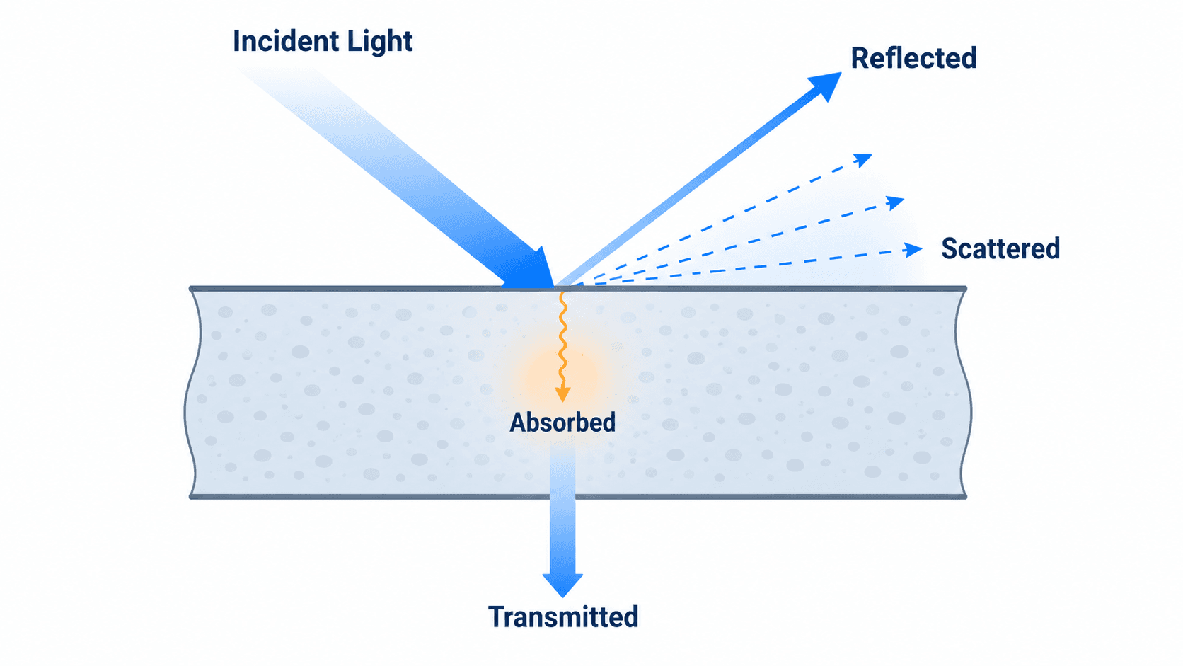
The first engineering question is not simply whether a material is “clear” or “opaque.” It is how the incident light is divided between reflection, transmission, absorption, and scattering for the wavelength range that matters.
What Are Optical Properties?
Optical properties are measurable behaviors that describe the interaction between a material and electromagnetic radiation. In most engineering applications, this means ultraviolet, visible, and infrared light, although the same principles can extend into other parts of the electromagnetic spectrum.
The most important optical properties include refractive index, reflectance, transmittance, absorptance, scattering, transparency, translucency, opacity, color, emissivity, emittance, and optical band gap. These properties are controlled by atomic structure, bonding, electron behavior, material composition, microstructure, surface finish, coatings, defects, and processing history.
| Optical property | What it describes | Why engineers care |
|---|---|---|
| Refractive index | How much light bends as it enters or travels through a material. | Critical for lenses, optical fibers, prisms, sensors, and transparent covers. |
| Reflectance | The portion of incident light reflected from a surface. | Controls glare, mirror behavior, solar reflectance, coatings, and thermal radiation surfaces. |
| Transmittance | The portion of light that passes through a material. | Used for windows, glazing, displays, lenses, filters, optical fibers, and protective transparent barriers. |
| Absorptance | The portion of light absorbed by the material. | Affects heating, UV protection, solar energy capture, color, degradation, and thermal response. |
| Scattering | How light is redirected by roughness, particles, pores, grains, defects, or internal features. | Explains haze, translucency, diffuse reflection, cloudy polymers, ceramics, and rough surfaces. |
| Emittance / emissivity | How effectively a surface emits thermal radiation compared with an ideal blackbody. | Important for thermal imaging, radiative cooling, solar absorbers, spacecraft surfaces, and building materials. |
| Optical band gap | The photon energy where a semiconductor or material begins absorbing strongly. | Important for LEDs, photodiodes, photovoltaics, lasers, and optical sensors. |
Main Types of Optical Properties in Materials
Most practical optical questions can be reduced to a few material responses: light bends, reflects, passes through, scatters, is absorbed, or is emitted as radiation. The relative amount of each response depends on wavelength, chemistry, surface finish, internal structure, temperature, and thickness.
Reflection, Transmission, and Absorption
For a simplified light-energy balance, incident light is divided into reflected, transmitted, and absorbed portions. This is useful for thinking about windows, coatings, filters, solar absorbers, optical shields, and reflective surfaces.
- \(R\) Reflectance, or the fraction of incident light reflected by the material or surface.
- \(T\) Transmittance, or the fraction of incident light that passes through the material.
- \(A\) Absorptance, or the fraction of incident light absorbed and converted to internal energy, heat, or electronic excitation.
Refraction and Refractive Index
Refraction occurs when light changes direction as it moves between materials with different refractive indices. In engineering, refractive index matters for lenses, optical fibers, prisms, transparent covers, sensor windows, camera systems, and any design where the optical path must be controlled.
- \(n_1, n_2\) Refractive indices of the two materials at the wavelength being evaluated.
- \(\theta_1, \theta_2\) Incident and refracted angles measured from the normal to the surface.
Complex Refractive Index and Optical Constants
In more advanced materials work, the refractive behavior and absorption behavior are often described together using a complex refractive index. This is especially important for metals, semiconductors, thin films, coatings, and wavelength-dependent optical modeling.
The real part, \(n\), is associated with refraction and phase velocity. The imaginary part, \(k\), is the extinction coefficient and is associated with attenuation or absorption. This distinction helps explain why two materials can bend light similarly while absorbing very different amounts of energy.
Scattering, Haze, and Translucency
Scattering happens when light is redirected by surface roughness, pores, grain boundaries, particles, fibers, crystallites, scratches, or internal defects. A polymer sheet may transmit a large amount of light but still appear cloudy because scattered light reduces image clarity. This is why transmittance and transparency are related but not identical.
Color and Selective Absorption
Color is a visible result of wavelength-dependent absorption, reflection, or transmission. A material appears red when red wavelengths are reflected or transmitted more strongly than other visible wavelengths. Pigments, dyes, oxides, semiconductors, metals, and thin films can all create color through different optical mechanisms.
Emittance, Emissivity, and Thermal Radiation
Emittance and emissivity describe how effectively a surface emits thermal radiation. These properties are important when optical behavior overlaps with heat transfer, such as in thermal imaging, radiative cooling, solar absorbers, roof materials, spacecraft surfaces, furnaces, and infrared sensors.
Why Optical Properties Depend on Wavelength
Optical behavior is wavelength-dependent because photon energy changes across ultraviolet, visible, and infrared light. A material can be transparent in the visible range, absorb ultraviolet light, and partially reflect or absorb infrared radiation. This is one of the most important details missing from many basic definitions of optical properties.
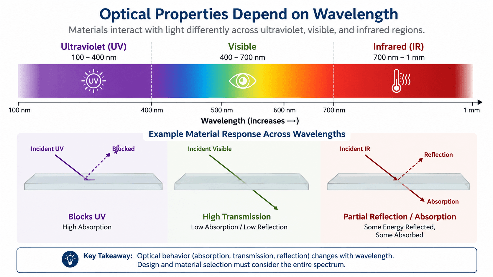
Visible Clarity Does Not Prove Full-Spectrum Performance
A transparent plastic cover may look clear to the eye but still block UV radiation. A glass pane may pass visible light while limiting parts of the infrared spectrum. A coating may be designed to reflect solar radiation while transmitting enough visible light for daylighting. Engineers usually evaluate optical properties over a wavelength band, not just at one visual appearance.
Photon Energy and Optical Band Gap
Optical band gap is especially important for semiconductors and optoelectronic materials. It identifies the photon energy where a material begins absorbing strongly. This helps determine whether a semiconductor is useful for solar cells, LEDs, photodiodes, lasers, or wavelength-specific sensors.
- \(E\) Photon energy, commonly evaluated in joules or electronvolts depending on the application.
- \(h\) Planck’s constant.
- \(c\) Speed of light in vacuum.
- \(\lambda\) Wavelength of the light being evaluated.
Always match the optical property data to the operating wavelength range. Visible-light transparency, UV resistance, infrared absorption, and thermal emittance can describe very different material behavior.
Transparent, Translucent, and Opaque Materials
Transparency, translucency, and opacity are practical descriptions of how light passes through a material, but they are controlled by measurable optical properties. The key difference is not just how much light passes through, but whether the transmitted light remains organized enough to form a clear image.
| Visual behavior | What it means | Optical reason | Engineering example |
|---|---|---|---|
| Transparent | Light passes through with enough clarity to see objects or images. | High transmittance with low scattering and low absorption in the wavelength range of interest. | Clear glass, optical acrylic, camera lens material, optical fiber core. |
| Translucent | Light passes through, but image clarity is reduced or lost. | Transmission occurs, but scattering redirects light inside or at the surface. | Frosted glass, cloudy polymer sheet, light diffuser, some thin ceramics. |
| Opaque | Little or no light passes through the material. | Reflection, absorption, and internal scattering dominate over transmission. | Metal plate, ceramic tile, pigmented plastic, thick coating. |
This distinction matters because a material with high transmittance is not automatically optically clear. If the material scatters light strongly, it may be useful as a diffuser but poor as a window, lens, or imaging cover.
Optical Behavior by Engineering Material Class
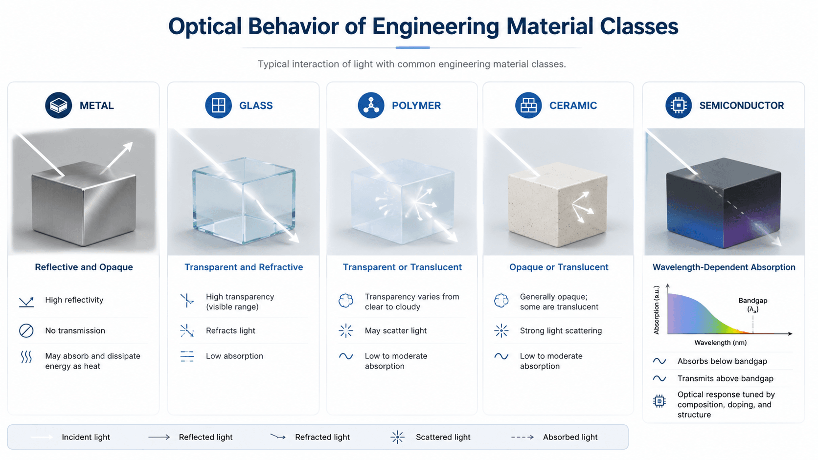
Material classes tend to show different optical behavior because their atomic bonding, electronic structure, microstructure, and surface condition are different. The visual and table below summarize typical trends, but final selection should always use measured data for the actual grade, thickness, coating, and surface finish.
| Material class | Typical optical behavior | Engineering implication |
|---|---|---|
| Metals | Usually reflective and opaque in visible light because free electrons strongly interact with electromagnetic waves. | Useful for mirrors, reflective coatings, shielding, radiant barriers, and surfaces where transmission is not desired. |
| Glass | Often transparent in visible light and strongly influenced by composition, impurities, coatings, and thickness. | Used for glazing, lenses, optical windows, labware, fibers, and protective transparent components. |
| Polymers | Can be transparent, translucent, colored, UV-stabilized, or cloudy depending on chemistry and processing. | Useful for covers, lenses, packaging, light diffusers, display layers, and low-cost optical components. |
| Ceramics | Often opaque due to scattering from grains, pores, and second phases, though some engineered ceramics can be translucent or transparent. | Used where heat resistance, wear resistance, electrical insulation, or special optical windows are needed. |
| Semiconductors | Strongly wavelength-dependent because absorption is tied to electronic band structure and optical band gap. | Central to LEDs, photodiodes, image sensors, solar cells, lasers, and optoelectronic devices. |
Optical Properties Examples in Engineering Materials
Optical properties become easier to understand when they are tied to real materials and components. The same property can be desirable in one application and a problem in another. For example, scattering is useful in a light diffuser but harmful in an imaging lens.
| Material or component | Important optical property | Engineering meaning |
|---|---|---|
| Window glass | Visible transmittance, UV absorption, reflectance, and infrared response. | Allows daylight while controlling glare, heat gain, UV exposure, and occupant comfort. |
| Aluminum foil or polished metal | High reflectance and very low transmittance. | Useful as a reflective barrier, optical shield, or radiant heat reflector. |
| Frosted acrylic | Transmittance plus strong scattering. | Diffuses light for displays, signs, lighting panels, and architectural features. |
| Black coating | High visible absorptance and possibly high thermal emittance. | Used for solar absorption, thermal control, contrast improvement, or stray-light reduction. |
| Silicon wafer | Band-gap absorption and wavelength-dependent optical response. | Important for photovoltaics, photodiodes, image sensors, and semiconductor devices. |
| Low-emissivity coating | Infrared reflection and emittance control. | Used in glazing systems to improve thermal performance while preserving useful visible light transmission. |
How Engineers Use Optical Properties
Engineers use optical properties to control how light moves through a product, structure, device, or surface. The goal may be to maximize transparency, reduce glare, increase absorption, improve sensor response, block UV radiation, reflect heat, tune color, or control thermal emission.
- Optical components: lenses, prisms, windows, fibers, and transparent covers rely on refractive index, transmission, scattering, and surface quality.
- Energy systems: solar cells, solar absorbers, cool roofs, glazing, and thermal coatings depend on wavelength-specific absorption, reflection, and emission.
- Electronics and sensors: LEDs, photodiodes, cameras, displays, and infrared sensors use band gap, absorption spectra, optical filtering, and emissivity.
- Manufacturing and inspection: color, gloss, haze, reflectance, and surface scattering can reveal coating quality, roughness, contamination, or processing defects.
Optical performance is rarely controlled by the base material alone. Coatings, scratches, oxidation, dust, moisture, surface roughness, and aging can change the way a component reflects, transmits, absorbs, emits, or scatters light after it is installed.
What Controls the Optical Properties of a Material?
Optical properties are controlled by both the material itself and the condition in which the material is used. A datasheet value may not match field behavior if the tested sample had a different thickness, surface finish, coating, temperature, angle of incidence, polarization, or wavelength range.
| Control factor | Why it matters | Engineering implication |
|---|---|---|
| Wavelength range | UV, visible, near-infrared, and thermal infrared photons interact differently with the same material. | Select optical data for the operating spectrum, not just visible appearance. |
| Thickness | Absorption and scattering often increase as light travels through more material. | A thin sample may transmit light well while a thicker part appears darker or more opaque. |
| Surface roughness | Rough surfaces scatter light and reduce specular reflection or image clarity. | Polishing, texturing, abrasion, and wear can change glare, haze, and reflectance. |
| Microstructure | Grains, pores, inclusions, fibers, crystallites, and second phases redirect or absorb light. | Ceramics, composites, filled polymers, and coatings may behave differently than a pure base material. |
| Coatings and films | Thin layers can intentionally modify reflection, absorption, UV blocking, color, or emissivity. | Anti-reflective coatings, low-e coatings, tints, and protective films must be evaluated as part of the optical system. |
| Angle and polarization | Reflectance, transmittance, and scattering can change with viewing geometry and polarization state. | Optical systems with angled surfaces, coatings, lasers, or sensors may need geometry-specific data. |
| Temperature and environment | Heat, UV exposure, oxidation, moisture, and contamination can change optical response over time. | Outdoor, high-temperature, and radiation-exposed applications need durability checks, not just initial optical data. |
How Optical Properties Are Measured and Reported
Optical properties are commonly reported as spectra, which means the value is plotted or tabulated versus wavelength. Instead of asking whether a material has one fixed reflectance or transmittance, engineers usually ask how that value changes across the wavelength range of the application.
Common Measured Quantities
Reflectance, transmittance, absorptance, emittance, refractive index, extinction coefficient, and scattering are often measured using spectrophotometers, reflectometers, ellipsometers, integrating spheres, or specialized optical test setups. The correct method depends on whether the material is transparent, opaque, rough, thin-film coated, diffuse, or specular.
Surface Properties vs Bulk Properties
Some optical properties are dominated by the surface, while others depend heavily on the path length through the material. Reflectance is often controlled by surface finish, roughness, oxidation, and coatings. Transmission and absorption are often controlled by thickness, impurities, microstructure, and the bulk material itself.
Why Test Geometry Matters
Optical data can depend on angle of incidence, detector position, polarization, beam size, sample mounting, surface roughness, and whether the instrument captures diffuse or specular light. In advanced optical systems, polarization can also affect measured reflectance, transmittance, and scattering, especially at angled surfaces, coatings, and interfaces.
For final material selection, use optical data measured on a sample that matches the actual material grade, color, thickness, surface finish, coating stack, expected operating wavelength range, and test geometry.
Optical Material Selection Checklist
A strong optical material choice starts by defining what the light must do. The workflow and checklist below connect the desired optical behavior to the material property that should be reviewed.
Define the wavelength range first. Then decide whether the design needs transmission, reflection, absorption, scattering, filtering, color control, refraction, or emission control. After that, check material class, thickness, surface finish, coating options, measured spectra, aging, UV exposure, heat, abrasion, and contamination.
| Selection check | What to look for | Why it matters |
|---|---|---|
| Operating wavelength range | UV, visible, near-IR, mid-IR, thermal IR, or a specific sensor/LED wavelength. | Optical behavior can change completely outside the visible spectrum. |
| Required light path | Clear transmission, diffuse transmission, reflection, absorption, blocking, refraction, or emission. | The same material may be excellent for a diffuser but poor for an imaging window. |
| Surface finish and roughness | Polished, matte, textured, scratched, coated, oxidized, or contaminated surfaces. | Surface condition can dominate reflectance, glare, haze, and scattering. |
| Material thickness | Actual part thickness, not just test coupon thickness. | Absorption and scattering can increase with path length through the material. |
| Environmental durability | UV exposure, heat, moisture, abrasion, chemicals, and outdoor aging. | Optical performance can degrade even when mechanical performance remains acceptable. |
| Coating stack | Anti-reflective, low-emissivity, tint, UV-blocking, protective, or absorptive coating layers. | Coatings may control the final optical performance more than the base material. |
| Measurement basis | Wavelength range, angle, polarization, sample thickness, and diffuse/specular measurement method. | Two optical values are not directly comparable unless the test conditions are compatible. |
Optical Properties vs Other Material Properties
Optical properties are one part of a larger material selection process. A material that performs well optically may still fail if its strength, thermal behavior, electrical behavior, chemical resistance, or physical stability is not appropriate for the application.
| Related property group | Connection to optical behavior | Design example |
|---|---|---|
| Physical Properties | Density, phase, texture, and appearance can affect or help describe optical response. | A cloudy material may have internal pores or particles that scatter light. |
| Mechanical Properties | Strength, hardness, and scratch resistance affect optical durability in service. | A clear cover can lose optical clarity if it scratches or cracks easily. |
| Thermal Properties | Absorption and emission connect optical behavior to heating, cooling, and radiation. | A dark coating may absorb solar energy and raise surface temperature. |
| Electrical Properties | Electronic structure controls band gap, photoconductivity, and optoelectronic behavior. | Semiconductors absorb or emit light based on their band structure. |
| Chemical Properties | Oxidation, UV degradation, corrosion, and chemical exposure can change optical response. | A polymer may yellow under UV exposure even if it starts optically clear. |
Engineering Judgment and Field Reality
Ideal optical diagrams usually show smooth surfaces, uniform materials, and single-wavelength rays. Real components may include scratches, coatings, grain boundaries, adhesive layers, dust, oxidation, temperature gradients, and nonuniform thickness. These conditions can turn a clean optical design into a hazy, reflective, absorbing, or inconsistent field installation.
Engineers also need to separate appearance from performance. A black coating may look similar to another black coating in visible light but have very different solar absorptance or thermal emittance. A clear polymer may be acceptable indoors but yellow, haze, or crack after UV exposure. A polished metal surface may start reflective and become dull after corrosion or abrasion.
Do not judge optical performance from color alone. Color is only the visible result of wavelength-dependent reflection and absorption; it does not tell you how the material behaves in UV, infrared, or thermal radiation bands.
When This Breaks Down
Simplified optical property explanations are useful for learning, but they break down when the material, surface, or light source is more complex than the model assumes. In those cases, measured spectra, system testing, or more advanced optical modeling may be needed.
- Broadband light sources: Sunlight, LEDs, lamps, and thermal emitters contain ranges of wavelengths, so one optical value may not represent the full behavior.
- Rough or textured surfaces: Specular reflectance values may not capture diffuse scattering from matte surfaces, worn surfaces, or textured coatings.
- Thin films and multilayers: Interference, coating thickness, and layer sequence can make optical response very different from the base material.
- Semiconductors and photonic materials: Band gap, doping, crystal quality, and device architecture can dominate absorption and emission behavior.
- Field exposure: UV, oxidation, moisture, abrasion, and contamination can shift optical performance away from initial laboratory data.
Common Mistakes and Practical Checks
Many optical property mistakes come from treating a complex spectrum-dependent behavior as a simple yes-or-no description. The most reliable approach is to define the wavelength band, optical function, material condition, and measurement basis before comparing materials.
- Confusing transparency with transmittance: High transmittance does not guarantee visual clarity if scattering creates haze.
- Ignoring wavelength dependence: Visible transparency does not prove UV transmission, infrared transparency, or thermal radiation behavior.
- Using polished-sample data for rough surfaces: Surface finish can change reflection and scattering dramatically.
- Forgetting thickness: A thin sheet may transmit light while a thicker part absorbs or scatters too much light.
- Comparing uncoated and coated materials as if they are equivalent: Coatings can control reflectance, UV blocking, color, emissivity, and durability.
- Relying on color alone: Color does not fully describe reflectance, absorptance, transmittance, or emittance outside the visible spectrum.
The biggest mistake is choosing an optical material from a single visible-light property when the real application depends on a full wavelength band, a specific surface condition, or long-term environmental exposure.
Useful References and Optical Property Data Sources
Optical property data is most useful when it states the measured quantity, wavelength range, sample condition, and test geometry. Reflectance, transmittance, absorptance, emittance, refractive index, and extinction coefficient can depend on how the sample is measured, not just on the material name.
- NIST optical properties resource: NIST overview of optical property modeling explains bulk optical properties such as complex refractive index, absorption, and reflectance across the electromagnetic spectrum.
- Project-specific criteria: Final material selection may also depend on owner requirements, manufacturer data, test standards, service exposure, coating specifications, and optical performance targets.
- Engineering use: Use authoritative references to understand the property, then confirm final choices with measured data for the actual material, geometry, coating, surface finish, and operating wavelength.
Frequently Asked Questions
Optical properties describe how a material interacts with light or electromagnetic radiation. Important examples include refractive index, reflectance, transmittance, absorptance, scattering, opacity, color, emissivity, and wavelength-dependent absorption.
Common examples include refractive index, reflectance, transmittance, absorptance, scattering, transparency, translucency, opacity, color, emittance, emissivity, and optical band gap. The most important property depends on whether the material is being used for lenses, coatings, displays, sensors, solar energy, lighting, or thermal radiation control.
Optical properties depend on wavelength because photons with different energies interact differently with electrons, bonds, defects, surface features, and crystal structure. A material can transmit visible light while absorbing ultraviolet radiation or reflecting infrared radiation.
Yes. Optical properties are wavelength-dependent, so a material can transmit visible light while absorbing ultraviolet light or reflecting infrared radiation. Engineers evaluate optical data over the wavelength range used in the application rather than relying only on visual appearance.
Transparency is a practical description of how clearly light passes through a material, while transmittance is a measurable ratio of transmitted light to incident light. A material may have high transmittance but still look hazy if it scatters light strongly.
Summary and Next Steps
Optical properties describe how engineering materials interact with light through reflection, transmission, absorption, scattering, refraction, emission, wavelength response, and electronic band structure. They are essential for understanding transparent materials, reflective surfaces, coatings, sensors, displays, solar devices, lenses, optical fibers, and semiconductors.
The most important practical step is to define the wavelength range and optical function before comparing materials. Surface finish, thickness, microstructure, coatings, temperature, polarization, field exposure, and measurement method can change optical performance just as much as the base material itself.
Where to go next
Continue your learning path with related Turn2Engineering materials science resources.
-
Material Properties
Review the broader material property categories that optical behavior fits into.
-
Physical Properties
Learn how observable material characteristics such as density, color, texture, and phase relate to engineering selection.
-
Electrical Properties
Connect optical band gap, semiconductors, and electronic structure to electrical material behavior.