Key Takeaways
- Definition: Load path analysis traces how forces travel through a structure until they reach the foundation and supporting ground.
- Use case: It helps engineers find missing connections, discontinuous framing, weak transfer points, and unsafe assumptions before construction.
- Main decision: The key question is whether every gravity and lateral load has a continuous, strong, stiff, and constructible route.
- Outcome: A clear load path improves member sizing, connection detailing, structural safety, constructability, and design review quality.
Table of Contents
Introduction
In brief: Load path analysis follows structural forces from where they enter a system to where they safely discharge into the foundation.
Who it’s for: Students and design reviewers.
For informational purposes only. See Terms and Conditions.
The strongest structure is not just a collection of strong members. It is a connected system where every load has a clear route through framing, connections, supports, and soil.
Load path analysis infographic
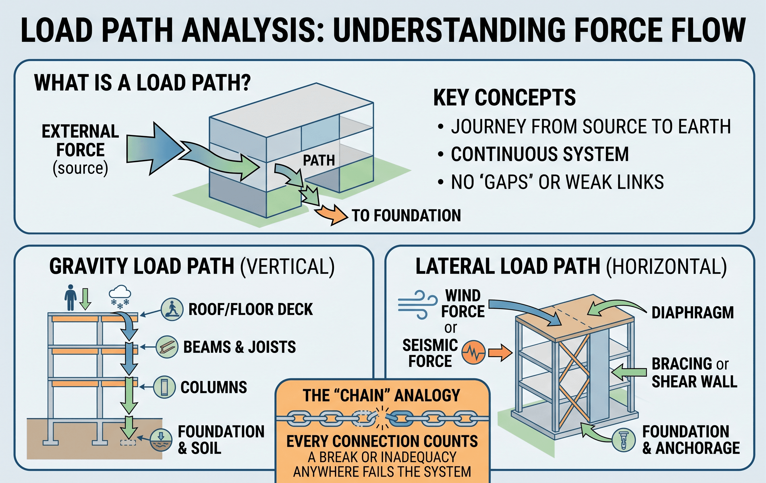
Notice that the load path is not just vertical. Gravity loads usually travel downward, while wind and seismic loads may move through diaphragms, collectors, shear walls, frames, anchors, foundations, and soil resistance.
What is load path analysis?
Load path analysis is the process of identifying, tracing, and checking the route that loads follow through a structural system. A load may begin as the weight of a floor finish, an occupant, a storage rack, wind pressure on a wall, seismic inertia in a floor diaphragm, snow on a roof, equipment vibration, soil pressure, or a construction load. The analysis asks where that force goes next, what element carries it, what connection transfers it, and where it ultimately reaches stable support.
In structural engineering, the load path is the organizing logic behind the whole structure. It connects structural loads, members, diaphragms, bracing systems, walls, frames, foundations, and the supporting ground into one continuous load-resisting system. When the load path is clear, calculations become easier to check. When it is unclear, even strong individual members may not produce a safe structure.
A simple gravity example is a person standing on a floor. The load moves from the floor surface into a slab or deck, then into joists or beams, then into girders, then into columns or walls, then into footings, and finally into soil. A lateral example is wind pressure on a building face. That pressure may move through cladding attachments, wall framing, floor or roof diaphragms, collectors, braces or shear walls, hold-downs, foundations, and soil resistance.
A load path is complete only when the force can be followed through members and connections all the way to a stable support without a missing link, unrealistic assumption, or unverified transfer point.
Gravity and lateral load paths
Most structural systems carry more than one type of load path at the same time. Gravity loads tend to move downward through floors, beams, columns, walls, and foundations. Lateral loads move sideways, overturning, or uplifting parts of the structure before they are resolved into foundations and soil. Good load path analysis separates these systems first, then checks how they interact.
Gravity load path
Gravity load path analysis begins with tributary areas. A slab area contributes load to a joist, a joist contributes reaction to a beam, a beam contributes reaction to a girder or column, and a column contributes axial load to the foundation. The engineer checks whether each member and connection is sized for the load it actually receives, not just the load shown on a simplified framing plan.
Gravity paths are often controlled by bending, shear, bearing, axial compression, deflection, punching shear, connection reaction, or foundation bearing pressure. In real buildings, gravity paths may also be affected by openings, transfer beams, setbacks, cantilevers, discontinuous columns, heavy equipment, façade loads, and construction staging.
Lateral load path
Lateral load paths are usually more complex because forces must move horizontally and vertically. Wind pressure, seismic inertia, and other lateral effects are collected by cladding, decks, diaphragms, collectors, chords, braces, shear walls, moment frames, anchors, foundations, and soil. The lateral system must resist shear, overturning, drift, uplift, sliding, torsion, and connection demands.
A common design mistake is treating the lateral system as a single element instead of a chain. A shear wall may have enough in-plane capacity, but the system can still fail if diaphragm collectors are missing, chords are undersized, hold-downs are not anchored, or the foundation cannot resist overturning.
| Load path type | Typical starting point | Typical transfer elements | Common control checks |
|---|---|---|---|
| Gravity | Floor, roof, equipment, stored materials | Deck, slab, joists, beams, girders, columns, walls, footings | Bending, shear, axial load, bearing, deflection, foundation pressure |
| Wind | Cladding, roof, walls, rooftop equipment | Attachments, wall framing, diaphragm, collectors, frames, shear walls, anchors | Uplift, sliding, overturning, drift, connection strength |
| Seismic | Mass distributed through floors, roofs, walls, equipment | Diaphragms, collectors, vertical lateral-force-resisting system, foundations | Base shear, drift, torsion, diaphragm force, collector force, anchorage |
| Temporary construction | Shoring, equipment, stored materials, partial framing | Incomplete framing, temporary bracing, shores, partially cured concrete | Stability, sequencing, temporary support capacity, local overstress |
How engineers perform load path analysis
A useful load path review moves from big-picture structure to detailed connection checks. The goal is not to create a complicated diagram for its own sake. The goal is to prove that every load can move through the intended system safely and predictably.
1. Identify the load source → 2. Define tributary area or force distribution → 3. Trace member-to-member transfer → 4. Check connections → 5. Follow reactions into foundations → 6. Verify soil, stability, and continuity.
Step 1: Identify the load source
Start with the action applied to the structure. For gravity loads, this may be dead load, live load, snow load, equipment weight, façade weight, or stored material. For lateral loads, it may be wind pressure, seismic inertia, soil pressure, flood load, impact, or thermal restraint. The engineer should also identify whether the load is permanent, transient, reversible, cyclic, dynamic, or construction-stage dependent.
Step 2: Determine where the load is collected
Loads do not jump directly to columns or walls. They are collected by surfaces and framing. A roof deck collects snow and dead load. A floor diaphragm collects lateral inertial force. Cladding transfers wind pressure to girts, studs, or backup framing. A retaining wall collects lateral earth pressure. This first collection step is where many errors begin because architectural openings, offsets, and discontinuities can change tributary behavior.
Step 3: Trace the force through each structural element
After collection, follow the force through each member. In a simple beam line, this may mean slab to beam to column to footing. In a lateral system, it may mean diaphragm shear to collector to brace frame to base plate to anchor rods to footing to soil. At each step, ask whether the next element is actually connected, stiff enough to attract the assumed load, and strong enough to transfer it.
Step 4: Check connections and interfaces
Connections complete the load path. Bolts, welds, anchor rods, embedded plates, reinforcement development, bearing seats, hold-downs, straps, diaphragms, chords, and collectors often control real behavior. A member can be strong enough while the connection is not. For that reason, load path analysis should always include connection demand and not stop at member capacity.
Step 5: Confirm foundation and ground support
The load path is not complete when the force reaches the bottom of a column. Foundations must distribute reactions into the soil or rock without unacceptable bearing pressure, settlement, sliding, overturning, or uplift. For more background on this part of the system, see foundation design.
Useful equations for checking a load path
Load path analysis is more of a workflow than one single formula. Still, several basic equations help engineers keep the force trail consistent. The most important idea is equilibrium: forces and moments must balance at each member, connection, diaphragm, and support.
These equilibrium equations are the foundation of structural analysis. If a beam, frame, diaphragm, shear wall, or foundation is assumed to be in static equilibrium, the applied loads and reactions must balance. When they do not, the load path is either incomplete, incorrectly modeled, or missing a reaction.
Tributary load transfer
For many gravity checks, a distributed load is estimated from tributary area. This helps determine how much load a beam, girder, column, or wall receives from a floor or roof system.
- P Resulting force or reaction, commonly in lb, kip, N, or kN.
- q Uniform area load, commonly in psf, kPa, lb/ft², or kN/m².
- At Tributary area contributing load to the element, commonly in ft² or m².
Connection demand check
For a load path to be continuous, connection capacity must be greater than or equal to the factored or required demand. The exact code format depends on the material and design method, but the concept is simple.
In strength design notation, \(R_u\) is the required strength from applied load combinations, \(R_n\) is nominal resistance, and \(\phi\) is the resistance factor. The same logic applies whether the check involves a beam reaction, collector splice, hold-down, weld, bolt group, bearing seat, base plate, or anchor rod.
Do not check only the largest member. Trace the force into and out of that member, because the weakest part of the load path is often a connection, support, or transfer detail.
Worked example: tracing a floor load to the foundation
Consider a simple office floor bay framed with a slab on metal deck supported by steel beams. The floor design load is assumed to be \(100 \text{ psf}\), including dead load and live load for this simplified example. One interior beam supports a tributary width of \(10 \text{ ft}\) over a span of \(24 \text{ ft}\).
1. Convert area load to line load
The beam receives load from its tributary width. The line load is:
This means the beam must be checked for a uniform line load of \(1000 \text{ lb/ft}\), before applying any required code load factors or separate load combinations.
2. Estimate simple-span reactions
For a simply supported beam with uniform load, each end reaction is:
The load path now moves from slab to beam, then from beam ends into supporting girders or columns. The beam connection must transfer approximately 12 kip at each end, adjusted as required by actual load combinations, connection eccentricity, and framing assumptions.
3. Continue the force into the supporting system
If the reaction frames into a girder, the girder must be checked for that concentrated load along with reactions from other beams. If the girder frames into a column, the column axial load increases. If the column bears on a footing, the footing and soil pressure must be checked. The load path is not complete until the reaction has been followed into the ground.
After calculating a reaction, ask: what physically receives this force, how is it connected, and where does the force go after that?
Common load path discontinuities
A discontinuity occurs when the intended route for force is interrupted, offset, weakened, or left undefined. Some discontinuities are obvious, such as a column that stops at a transfer level. Others are subtle, such as a diaphragm opening that prevents shear from reaching a braced frame or an architectural wall layout that hides an unsupported load-bearing wall.
- Discontinuous columns: Columns that stop above parking levels, lobbies, transfer floors, or open retail spaces require transfer beams, walls, trusses, or slabs designed for concentrated reactions.
- Diaphragm openings: Stairs, shafts, skylights, atria, and mechanical openings can interrupt diaphragm shear and chord forces.
- Offset shear walls: Walls that do not stack vertically can create transfer forces, torsion, collector demands, and local foundation reactions.
- Missing collectors: Lateral forces may not reach shear walls or frames unless collectors and chords are detailed for the required force.
- Weak anchorage: Hold-downs, anchor rods, embedded plates, and sill connections can control uplift or overturning resistance.
- Uncoordinated penetrations: Field-cut holes, sleeves, embeds, and MEP penetrations can interrupt load-carrying elements.
- Foundation mismatch: A superstructure load path may be clear, but foundation stiffness, settlement, or soil bearing may redirect forces.
Do not assume a load “finds its way” to the foundation. Structures redistribute forces through stiffness, not intention, and redistribution can overload elements that were never designed to carry the demand.
Engineering judgment and field reality
Real structures rarely match a perfectly clean textbook diagram. Architectural openings, mechanical equipment, construction tolerances, connection eccentricities, field modifications, and material variability all affect how loads move. Load path analysis is where engineering judgment turns a theoretical model into a buildable structure.
In design review, experienced engineers often start by sketching the main force paths before reviewing member sizes. This quickly reveals whether the building has a coherent structural concept. If the sketch cannot show how gravity, wind, and seismic loads reach the ground, detailed calculations may only be refining an incomplete idea.
Field reality also matters during construction. Temporary bracing may be needed before the permanent load path is complete. Concrete may not have reached design strength. Steel frames may be unstable before diaphragms, deck, bridging, or lateral bracing are installed. Masonry or tilt-up walls may need temporary support until final diaphragms and anchors are connected.
A load path that exists only after final construction may not protect the structure during erection, shoring removal, temporary storage, or staged loading.
What controls the design?
Load path decisions are often controlled by more than member strength. Stiffness, drift, vibration, deflection, crack width, foundation settlement, ductility, redundancy, constructability, inspection access, fire protection, corrosion, fatigue, and connection detailing can all control the final system. A rational load path is usually the one that is safe, inspectable, buildable, and robust under realistic conditions.
When this breaks down
Load path analysis breaks down when the simplified model no longer represents the structure’s actual behavior. This can happen because the structure is highly irregular, the stiffness assumptions are wrong, the load changes direction, the construction sequence changes the support conditions, or the foundation moves relative to the superstructure.
A common breakdown occurs when engineers trace force using only strength capacity and ignore stiffness. Loads tend to move through the stiffest available routes, especially in lateral systems. If one frame, wall, diaphragm segment, or foundation line is much stiffer than another, it may attract more force than a simple tributary assumption suggests.
Another breakdown occurs in highly discontinuous buildings. Transfer levels, podium structures, soft stories, offsets, setbacks, long cantilevers, large diaphragm openings, and irregular wall layouts can create force concentrations that require refined analysis. In these cases, simple hand sketches are still useful, but they should be supported by structural modeling, sensitivity checks, and careful detailing.
- Dynamic behavior: Vibration, seismic response, impact, fatigue, and machinery loads may not follow static assumptions.
- Nonlinear behavior: Cracking, yielding, buckling, uplift, sliding, and soil-structure interaction can change force distribution.
- Connection flexibility: Real connections may rotate, slip, yield, or attract eccentric forces not shown in idealized models.
- Construction stages: The final load path may not exist during erection, demolition, retrofit, or temporary shoring conditions.
- Hidden deterioration: Corrosion, rot, fatigue, cracking, settlement, and previous modifications can weaken the assumed path.
Common pitfalls and engineering checks
A good load path review is part analysis, part checklist, and part engineering judgment. The following checks help catch the failures that are easy to miss when drawings are reviewed one member at a time.
| Check | Question to ask | Why it matters |
|---|---|---|
| Continuity | Can the force be followed from source to ground? | Prevents missing links in framing, anchorage, diaphragms, and foundations. |
| Connection capacity | Is each connection designed for the transferred force? | Connections often control real structural behavior and failure sequence. |
| Stiffness compatibility | Does the assumed force split match relative stiffness? | Stiffer elements may attract more force than a simple tributary method suggests. |
| Foundation reaction | Can the foundation resist bearing, sliding, uplift, and overturning? | The load path must continue through the foundation into soil or rock. |
| Openings and offsets | Do shafts, setbacks, and transfer levels interrupt the path? | Discontinuities can create high collector, chord, and transfer demands. |
| Construction sequence | Does a safe temporary path exist before the final system is complete? | Partially built structures may be less stable than completed structures. |
Practical sanity checks
- Sketch the gravity load path before checking individual beam or column sizes.
- Sketch the lateral load path separately for each principal direction.
- Circle every transfer point, collector, hold-down, diaphragm opening, and foundation reaction.
- Check that reactions shown on drawings match the connection forces being detailed.
- Confirm that architectural openings do not cut through the intended force path.
- Review whether the structure has redundancy if one element is damaged or overloaded.
If a drawing set cannot answer “where does this load go next?” at each major member and connection, the load path needs more coordination.
Visualizing load path analysis
A useful way to visualize load path analysis is to draw arrows on the structural plan and section. Use one color or line style for gravity loads and another for lateral loads. Start at the load source, then trace each arrow through decks, slabs, beams, walls, frames, collectors, braces, foundations, and soil.
The drawing does not need to be artistic. It needs to be honest. If an arrow reaches a beam with no seat, a diaphragm with no collector, a wall with no hold-down, or a footing with no resistance to overturning, the sketch has found a design issue.
This approach is especially helpful for reviewing load bearing structures, load bearing walls, transfer floors, lateral systems, and retrofit projects where existing framing may not match original assumptions.
For review, sketch the load path in both plan and section because some discontinuities are only obvious when vertical and horizontal force transfer are seen together.
Relevant standards and design references
Load path analysis is a structural reasoning process, but the loads, combinations, material checks, and detailing requirements come from the governing code and project criteria. Always confirm the adopted code, local amendments, risk category, material standard, and project-specific design basis.
- International Building Code: Establishes model-code requirements for structural design, load combinations by reference, materials, construction, special inspections, and system-level safety provisions.
- ASCE/SEI 7: Provides minimum design loads and associated criteria for dead, live, snow, rain, wind, seismic, flood, ice, tsunami, and load combinations used to define required structural demand.
- ACI 318: Governs structural concrete design and detailing, including beams, slabs, columns, walls, foundations, reinforcement development, anchorage, shear transfer, and concrete connections.
- AISC 360: Provides generally applicable requirements for structural steel buildings and other steel structures, including member strength, stability, connection design, and design by LRFD or ASD.
- Project geotechnical report: Defines allowable bearing, settlement expectations, lateral earth pressure, sliding resistance, uplift considerations, and soil-structure interaction assumptions at the end of the load path.
Frequently asked questions
Load path analysis is the process of tracing forces through a structure from the point where they enter to the foundation and supporting ground. It verifies that slabs, beams, columns, walls, frames, diaphragms, connections, anchors, foundations, and soil work together as a continuous load-resisting system.
A continuous load path prevents forces from stopping at weak links or moving into unintended elements. Without continuity, loads can concentrate around openings, offsets, missing collectors, weak connections, or inadequate foundations, increasing the risk of cracking, excessive movement, instability, or failure.
Identify the load source, determine the tributary area or distribution, follow the force through each member and connection, then confirm that the reaction reaches a foundation and stable ground support. Gravity and lateral paths should be traced separately because they often use different structural elements.
Load path analysis explains where forces travel, while structural analysis calculates the resulting reactions, internal forces, deflections, stresses, and stability effects. A good design needs both: the load path defines the system, and structural analysis verifies that the system has enough strength and stiffness.
It breaks down when assumptions about stiffness, continuity, connection behavior, construction sequence, foundation restraint, or material behavior do not match the real structure. Irregular buildings, transfer levels, diaphragm openings, damaged structures, and nonlinear behavior often require more refined analysis.
Summary and next steps
Load path analysis is the structural engineering process of proving that every force has a continuous route from its source to stable support. It applies to gravity loads, wind loads, seismic forces, equipment reactions, earth pressure, temporary loads, and any other action that a structure must resist.
The practical workflow is straightforward: identify the load, determine how it is collected, trace it through members, check every connection, follow reactions into foundations, and verify that the ground can support the final demand. The difficult part is engineering judgment: recognizing stiffness effects, discontinuities, construction stages, hidden weak links, and details that are easy to miss on drawings.
A reliable load path makes the rest of the design more credible. Member sizing, connection design, diaphragm checks, bracing layout, foundation design, and field inspection all depend on knowing where the forces are intended to go.
Where to go next
Continue your structural engineering learning path with these related resources.
-
Study structural loads
Learn how dead, live, wind, snow, seismic, and environmental loads are defined before they enter the structural system.
-
Review structural analysis
Build the calculation foundation for reactions, shear, moment, deflection, stability, and member behavior.
-
Explore structural failure
See how missing load paths, weak connections, poor detailing, and incorrect assumptions can lead to structural distress or collapse.