Key Takeaways
- Pavement design is a system design: The final answer is not just asphalt or concrete thickness—it is a layered structure with traffic, subgrade, drainage, materials, and performance assumptions.
- Heavy trucks control damage: A small percentage of heavy trucks can dominate pavement loading, which is why ESALs or axle spectra are central to design.
- Subgrade and water can govern thickness: Weak, wet, expansive, or frost-susceptible soils can require stabilization, drainage improvements, thicker layers, or a different pavement type.
- Flexible and rigid pavements fail differently: Flexible pavements are commonly checked for rutting and fatigue, while rigid pavements depend heavily on slab thickness, support, joints, and load transfer.
Table of Contents
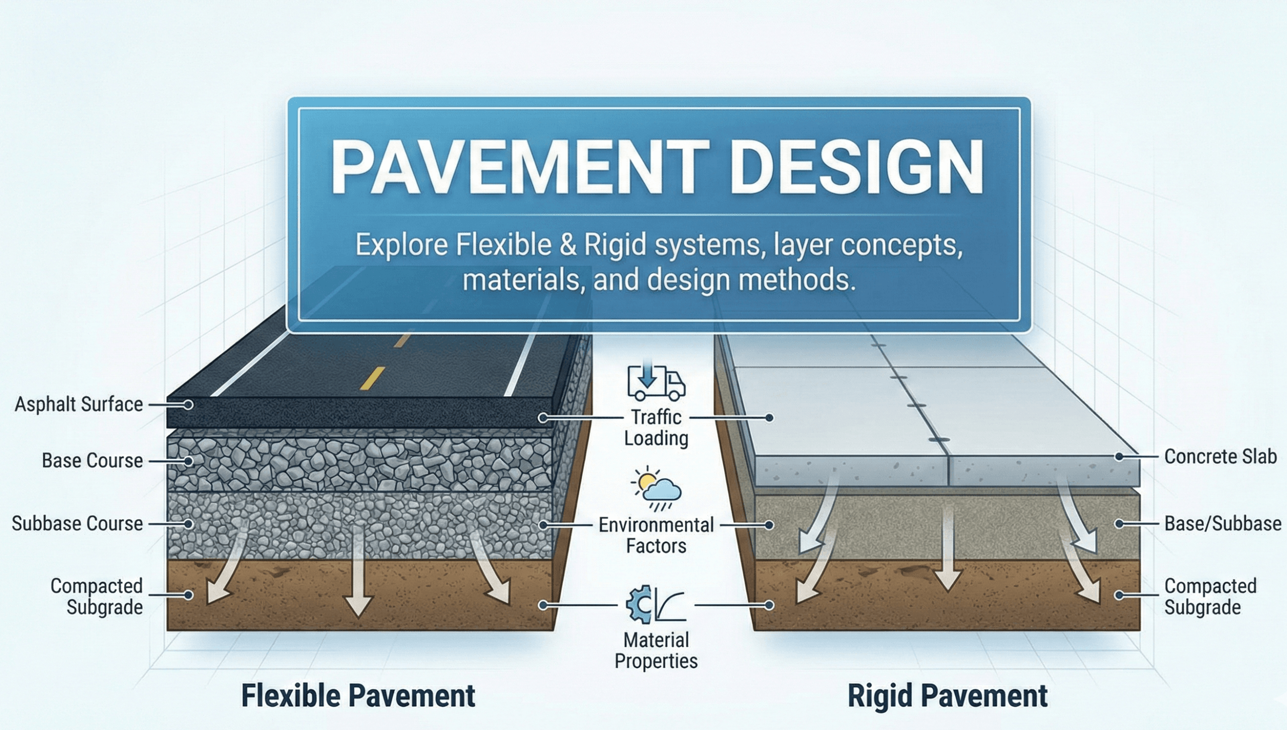
Featured diagram
Introduction
Pavement design is the process transportation engineers use to select a pavement type and determine the layer thicknesses needed for a roadway, parking lot, industrial yard, or airfield pavement to perform reliably over a planned service life. A good design must carry traffic loads while also managing water, temperature, construction variability, maintenance, and local agency requirements.
The core question is usually simple: how thick should the pavement be? The engineering answer is more involved. Thickness depends on traffic loading, truck growth, subgrade strength, drainage, pavement type, material properties, reliability, and the design method used by the governing agency.
What is pavement design?
Direct answer: Pavement design is the engineering process of selecting pavement materials and layer thicknesses so the pavement can safely and durably support expected traffic over its design life. It combines traffic loading, subgrade strength, drainage, climate, material properties, reliability, and agency standards into a buildable pavement section.
The design output is not only a total thickness. A complete pavement design should identify the surface layer, base, subbase, subgrade treatment, drainage details, and performance assumptions behind the selected section.
If you can’t explain why each layer is there—load distribution, drainage, frost protection, working platform, stabilization, or constructability—the design is not complete yet.
How pavement design works
Pavement design works by comparing the expected traffic demand to the structural capacity of a layered pavement system. The designer estimates how much loading the pavement will receive, evaluates the support provided by the subgrade and base layers, chooses practical materials, and sizes the section so it meets the required performance target.
Most pavement design methods follow the same basic logic even when the equations differ:
- Define the facility: roadway, parking lot, industrial yard, airfield, subdivision street, or highway.
- Estimate traffic loading: use ESALs, axle spectra, or agency traffic classes.
- Evaluate the foundation: determine CBR, resilient modulus, k-value, moisture sensitivity, and drainage condition.
- Select pavement type: flexible, rigid, composite, aggregate, or special-purpose pavement.
- Choose materials: asphalt mix, concrete slab, aggregate base, treated base, subbase, or stabilized subgrade.
- Calculate the required structure: determine structural number, slab thickness, or mechanistic-empirical performance response.
- Check constructability: verify lift thicknesses, compaction, joints, drainage outlets, transitions, and agency minimums.
Pavement design inputs checklist
Pavement thickness depends on inputs that describe loading, support, materials, environment, and design risk. The table below is a practical checklist before running any pavement design method.
| Input | What it means | Typical source | Why it matters |
|---|---|---|---|
| Facility type | Roadway, parking lot, industrial yard, airfield, or local street | Project scope / agency classification | Sets design life, loading assumptions, and acceptable pavement types |
| Design life | Number of years the pavement is expected to perform before major rehabilitation | Agency standard or owner requirement | Longer design lives accumulate more loading and usually require stronger sections |
| AADT | Annual average daily traffic | Traffic counts, DOT data, development studies | Base traffic volume used to estimate cumulative loading |
| Truck percentage | Fraction of traffic made up of trucks or heavy vehicles | Vehicle classification counts | Heavy vehicles cause most structural pavement damage |
| Traffic growth rate | Expected annual increase in traffic | Forecasts, planning studies, agency defaults | Can significantly increase cumulative ESALs over time |
| Directional and lane distribution | How much truck traffic uses the design direction and design lane | Agency tables or traffic analysis | Design is usually based on the critical lane, not total two-way traffic |
| ESALs or axle spectra | Cumulative load damage measure or axle load distribution | Traffic analysis / agency procedure | Directly drives structural thickness |
| Subgrade strength | CBR, resilient modulus, R-value, or k-value | Geotechnical report or agency correlation | Weak subgrades require thicker or improved pavement systems |
| Drainage condition | How quickly water leaves the pavement structure | Site grading, soils, groundwater, edge drain design | Poor drainage reduces support and accelerates distress |
| Layer materials | Asphalt, concrete, aggregate base, treated base, subbase, stabilization | Specifications and material availability | Material stiffness and durability control structural contribution |
| Reliability / performance target | Risk level and allowable serviceability loss or distress | Agency design method | Higher reliability generally requires a more conservative section |
Do not use a “typical” pavement thickness without checking traffic and subgrade. A low-volume parking lot and a truck-heavy industrial entrance can look similar on the surface but need very different pavement structures.
Types of pavements and when to use each
Pavement type selection is part of pavement design. The correct system depends on traffic loading, climate, construction staging, maintenance access, life-cycle cost, agency rules, and the way vehicles use the pavement.
Flexible pavements
Flexible pavements use asphalt and granular or stabilized layers to spread wheel loads downward through the pavement system. They are common for roadways, parking lots, and phased construction because they are relatively fast to build and can be rehabilitated with overlays.
Rigid pavements
Rigid pavements use concrete slab action to distribute loads over a wider area. They are often favored for heavy truck corridors, high-temperature regions, intersections, bus stops, ports, and industrial areas where slow heavy loads and high shear stresses can damage asphalt.
Composite pavements
Composite pavements combine pavement types, such as asphalt over concrete or asphalt over a stabilized base. They can improve ride quality or increase capacity, but the design must address bonding, reflection cracking, drainage, and the condition of the existing pavement.
| Project condition | Flexible pavement may fit better | Rigid pavement may fit better | Design watchout |
|---|---|---|---|
| Typical road or parking area | Good option when traffic is moderate and overlays are expected | May be used if long life or heavy loading justifies initial cost | Do not ignore subgrade moisture and drainage |
| Heavy truck route | Requires thicker asphalt and high-stability mixes | Often strong option due to slab action and rut resistance | Check joints, dowels, base support, and load transfer |
| Intersection / turning area | Can rut or shove under slow turning trucks unless designed carefully | Often preferred for high shear and braking zones | Uniform midblock sections may be inadequate at intersections |
| Utility-heavy corridor | Usually easier to cut, patch, and overlay | Can be harder to restore cleanly after utility cuts | Plan restoration details before construction |
| Poor subgrade | May need thick base, stabilization, geosynthetics, or undercutting | Can bridge support variations better, but still needs uniform support | Foundation treatment may matter more than surface type |
| Industrial yard / loading dock | Needs special attention to rutting and static loads | Often strong choice for slow heavy loads and point loading | Check wheel loads, tire pressure, turning, and drainage |
Pavement type should be selected after understanding where heavy vehicles stop, turn, park, brake, and accelerate. These high-stress zones often control the design more than straight midblock traffic.
Traffic loading for pavement design
Mixed traffic must be converted into a cumulative measure of pavement damage. A common method is to estimate Equivalent Single Axle Loads, usually called ESALs. Modern mechanistic-empirical design may use axle load spectra directly, but ESAL-based thinking is still common in many pavement design workflows.
Conceptual ESAL equation
A simplified ESAL workflow starts with yearly traffic, then applies truck percentage, directional distribution, lane distribution, and an equivalency factor.
- \(W_{18}\) Cumulative 18-kip ESALs over the design life
- \(\text{AADT}_{y}\) Annual average daily traffic in year \(y\)
- \(T\) Truck fraction of total traffic
- \(D\) Directional distribution factor
- \(L\) Design lane distribution factor
- \(EF\) Truck-to-ESAL equivalency factor
Why heavy trucks dominate pavement design
Passenger vehicles usually contribute relatively little structural damage compared with heavy trucks. That is why a site with modest total traffic but frequent loaded trucks can require a much stronger pavement than a higher-volume road dominated by passenger vehicles.
Always verify whether the traffic input represents total roadway traffic, one direction, or the design lane. Confusing these definitions can understate or overstate the design loading.
Subgrade support, drainage, and foundation behavior
Pavement performance depends heavily on the foundation below the surface. A pavement over a stiff, uniform, well-drained subgrade can perform very differently from the same thickness over a weak, wet, expansive, or variable subgrade.
Common ways engineers describe subgrade support
- CBR: California Bearing Ratio, commonly used in agency and low-volume pavement workflows.
- Resilient modulus, \(M_R\): a stiffness parameter used in mechanistic and AASHTO-based design methods.
- k-value: modulus of subgrade reaction, commonly used in rigid pavement design models.
- R-value or soil support value: used by some agencies as part of local pavement design systems.
Drainage conditions that change performance
- Surface infiltration: water enters through cracks, joints, shoulders, and utility cuts.
- Groundwater: high groundwater can keep the subgrade wet and reduce stiffness.
- Permeable layers without outlets: water can be trapped if drainage layers are not connected to working outlets.
- Flat grades: low longitudinal and cross slopes can slow water removal.
- Freeze-thaw: frost-susceptible soils can heave and weaken during thaw periods.
Laboratory strength values may not represent wet-season field behavior. If drainage is poor or groundwater is high, use conservative support assumptions or improve the foundation before simply adding surface thickness.
How pavement thickness is calculated
Pavement thickness is calculated using a design method selected by the agency or project owner. Common approaches include empirical AASHTO-style methods, agency standard sections, mechanistic-empirical design, and local pavement manuals.
Flexible pavement structural number
In many flexible pavement workflows, the pavement structure is represented by a Structural Number, or \(SN\). The structural number combines the contribution of asphalt, base, and subbase layers.
- \(SN\) Structural capacity index for the flexible pavement section
- \(a_i\) Layer coefficient for each material layer
- \(D_i\) Layer thickness, often in inches in SN-based methods
- \(m_i\) Drainage coefficient for granular layers
Rigid pavement slab thickness
Rigid pavement design selects a concrete slab thickness that can limit cracking, fatigue, faulting, and joint-related distress under repeated loads. Important variables include concrete strength, slab thickness, base support, k-value, joint spacing, dowels, load transfer, shoulders, climate, and reliability.
What the final thickness should specify
- Asphalt surface thickness or concrete slab thickness.
- Base type and thickness.
- Subbase type and thickness, if used.
- Subgrade stabilization, undercut, geotextile, or geogrid requirements.
- Drainage details, edge support, shoulders, outlets, or underdrains.
- Minimum lift thicknesses, compaction requirements, and construction tolerances.
A pavement section that looks correct mathematically can still fail if it cannot be compacted, drained, jointed, or maintained properly.
Worked example: flexible pavement structural number
This example is a concept demonstration, not a substitute for a governing agency design manual. It shows how a required structural number can be converted into a buildable flexible pavement section.
Example
Given: A two-lane roadway has an estimated design loading of \(W_{18}=2.0\times10^{6}\) ESALs over a 20-year design life. The subgrade is moderate, drainage is fair, and the design method requires \(SN_{\mathrm{req}}=4.2\).
Assume: asphalt coefficient \(a_1=0.44\), aggregate base coefficient \(a_2=0.14\), and drainage coefficient \(m_2=0.95\).
Trial section 1: 6 inches asphalt and 10 inches base
Because \(3.97 < 4.2\), the trial section does not meet the required structural number.
Trial section 2: 7 inches asphalt and 10 inches base
Because \(4.41 \ge 4.2\), the section meets the structural number requirement. A real design would still need checks for layer minimums, lift thicknesses, drainage, materials, subgrade treatment, and agency requirements.
Do not copy example coefficients into a real project without confirming the governing design method. Agencies define allowable coefficients, material classes, reliability assumptions, serviceability criteria, drainage factors, and minimum thickness rules.
Common pavement design failure modes
Strong pavement design connects calculations to field performance. The table below links common design misses to the distress patterns they can create.
| Design issue | Likely distress | Why it happens | Design response |
|---|---|---|---|
| Underestimated truck loading | Fatigue cracking, rutting, early overlay need | Actual load repetitions exceed design demand | Use defensible truck counts, growth, lane factors, and ESAL assumptions |
| Weak or variable subgrade | Alligator cracking, deformation, localized failures | Support is lower than assumed or not uniform | Use stabilization, undercut, thicker base, geosynthetics, or better drainage |
| Poor drainage | Stripping, pumping, base weakening, frost damage | Water reduces stiffness and accelerates load-related damage | Improve slopes, outlets, edge drains, shoulder details, and material selection |
| Inadequate joint design in concrete | Faulting, corner breaks, spalling, pumping | Slabs move and transfer load poorly at joints | Check joint spacing, dowels, tie bars, base support, and sealing details |
| Thin lifts or poor compaction | Raveling, rutting, permeability, premature cracking | Materials do not achieve intended density or durability | Use practical lift thicknesses and construction quality control |
| Ignoring high-stress areas | Rutting, shoving, cracking at entrances and intersections | Slow heavy loads and turning create severe shear demand | Thicken or modify sections at intersections, docks, stops, and truck turns |
Pavement design workflow you can follow
Use this workflow as a practical design outline. It is general enough for learning, but structured like the process used on real transportation projects.
- Define the project: facility type, owner, roadway class, design speed, traffic use, and construction constraints.
- Select the design standard: identify the governing state DOT, municipal, FAA, AASHTO, or owner method.
- Collect traffic data: AADT, trucks, vehicle classes, growth rate, axle loads, and lane distribution.
- Determine design loading: calculate ESALs or axle spectra for the design lane.
- Characterize the foundation: review borings, CBR, resilient modulus, groundwater, frost, and moisture sensitivity.
- Choose pavement type: compare flexible, rigid, composite, or aggregate options.
- Select materials: choose surface, base, subbase, stabilization, and drainage materials.
- Calculate required thickness: use the governing procedure to determine structural capacity or slab thickness.
- Check constructability: verify lift thicknesses, compaction, joints, utility cuts, edge support, and phasing.
- Review life-cycle performance: compare maintenance, rehabilitation, risk, and long-term cost.
- Document assumptions: record traffic factors, subgrade values, material coefficients, reliability, and final section logic.
Before finalizing the design, test sensitivity. Ask what happens if truck traffic is 20% higher, the subgrade is wetter than expected, or one construction lift cannot be compacted properly.
Visualizing the pavement design decision chain
A strong pavement design can be visualized as a decision chain: facility type sets the design context, traffic loading sets demand, subgrade and drainage set foundation behavior, materials set structural contribution, and standards define acceptable risk.
A useful supporting diagram for this page would show: “Define project” → “Estimate traffic loading” → “Evaluate subgrade and drainage” → “Select pavement type” → “Calculate required structure” → “Choose buildable layers” → “Check performance and details” → “Finalize pavement section.”
Relevant standards and design references
Pavement design is usually governed by agency-specific requirements. National methods and references are useful, but the project owner or jurisdiction often controls the allowable pavement types, design traffic categories, material coefficients, minimum thicknesses, drainage requirements, and construction specifications.
- FHWA pavement design and analysis: FHWA provides pavement design, analysis, pavement policy, life-cycle cost, and mechanistic-empirical design resources. Review FHWA pavement design and analysis resources.
- FHWA pavement design policy: FHWA describes pavement design as a project-level engineering and economic effort to optimize pavement type and thickness for project objectives and life-cycle cost. Read FHWA pavement design policy context.
- State DOT pavement design manuals: State agencies often publish the governing design procedures for flexible and rigid pavement. See FDOT pavement design publications.
- Local and municipal standards: Local streets, subdivision roads, parking lots, and utility restorations may follow municipal standard details rather than highway design procedures.
Always confirm which document is contractually governing the pavement design. A general educational equation should never override a state DOT, municipal, airport, industrial owner, or project-specific design requirement.
Frequently asked questions
Pavement design is the engineering process of selecting pavement materials and layer thicknesses so a pavement can carry expected traffic loads over its design life while accounting for subgrade strength, drainage, climate, reliability, construction, and agency requirements.
Pavement thickness is calculated by estimating traffic loading, evaluating subgrade support, selecting pavement materials, choosing a design method, and sizing the layers so the pavement meets required structural capacity and performance criteria.
ESAL stands for Equivalent Single Axle Load. It converts mixed truck traffic into an equivalent number of standard axle load repetitions so engineers can estimate cumulative pavement damage over the design life.
Flexible pavement design focuses on asphalt and granular layers distributing load through the structure, while rigid pavement design focuses on a concrete slab carrying loads through slab action. Flexible pavements are often checked for rutting and fatigue, while rigid pavements depend heavily on slab thickness, joints, support, and load transfer.
Drainage matters because water can weaken the subgrade and base, reduce stiffness, accelerate asphalt stripping, contribute to pumping in concrete pavements, and increase freeze-thaw damage.
Summary and next steps
Pavement design is the structured process of selecting pavement type and layer thicknesses so a pavement can support expected traffic loads over its design life. The key inputs are traffic loading, subgrade support, drainage, climate, materials, reliability, and governing design standards.
A strong pavement design does more than meet a thickness equation. It explains how the structure distributes load, how water is managed, how the subgrade is treated, how the pavement will be built, and how the section will perform at high-stress locations such as intersections, loading docks, industrial entrances, and utility cut areas.
Where to go next
Continue your learning path with these related transportation engineering topics.
-
Flexible pavement design
Go deeper into asphalt layer design, structural number, rutting, fatigue, and overlay strategies.
-
Rigid pavement design
Learn concrete slab thickness, joint design, load transfer, base support, and common rigid pavement distresses.
-
Highway Design
Connect pavement design to roadway geometry, traffic operations, drainage, safety, and construction constraints.
-
Transportation Engineering hub
Explore additional transportation engineering resources, design guides, and related topics.