
Direct Answer
A surge arrester is an overvoltage-protection device that normally remains high impedance, then conducts surge current when a lightning or switching transient pushes system voltage above its protective level. Modern medium- and high-voltage arresters commonly use metal-oxide varistors (MOVs) to limit the voltage seen by transformers, cables, bushings, switchgear, and line insulation.
Good arrester application is an insulation-coordination problem, not a simple voltage-match problem. Engineers verify MCOV, rated voltage, temporary-overvoltage capability, residual voltage, energy duty, discharge-current capability, equipment BIL/insulation withstand, grounding, lead length, physical placement, housing/environmental duty, and system grounding before relying on an arrester for protection.
Surge Arrester at a Glance
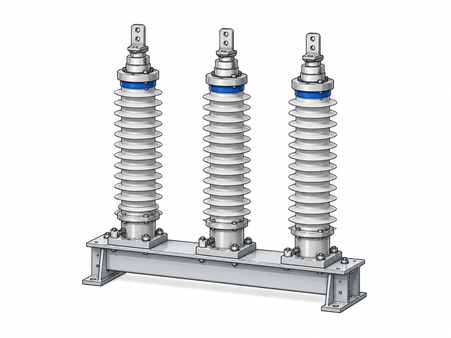
Table of Contents
- How Surge Arresters Work
- Surge Arrester vs. Lightning Arrester & SPD
- Types of Surge Arresters
- MCOV, Rated Voltage, TOV & Residual Voltage
- Insulation Coordination & BIL
- Where Surge Arresters Are Installed
- Lead Length & Grounding
- Line Surge Arresters
- Failure Modes & Inspection
- Engineering Review Checklist
How Does a Surge Arrester Work?
Modern metal-oxide surge arresters use nonlinear MOV blocks. At normal system voltage, the MOV stack conducts only a small leakage current. When a steep overvoltage appears, the MOVs conduct heavily and divert surge current toward ground while holding the protected terminal to a lower residual voltage.
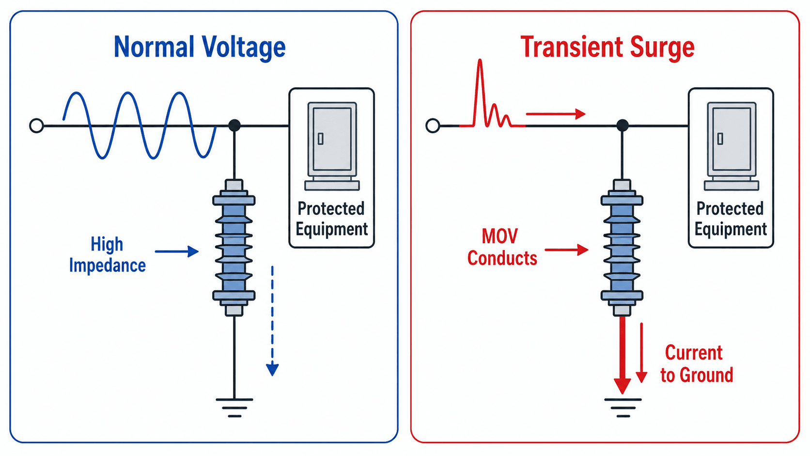
Normal Voltage
The arrester must withstand the actual phase-to-ground operating voltage continuously without excessive current or heating. That is why MCOV is a central selection value.
Surge Event
During a lightning or switching surge, the nonlinear MOV characteristic causes current to rise rapidly while voltage increases much less dramatically. The arrester therefore limits—but does not eliminate—the transient voltage.
After the Surge
When the transient disappears, the arrester must return to its low-leakage state. If system voltage remains abnormally high for too long, the arrester can continue dissipating energy and may thermally fail. Temporary overvoltage behavior therefore matters just as much as impulse behavior.
A surge arrester is a voltage-limiting device. It does not “absorb all lightning” and it does not reduce voltage to zero; the protected equipment still sees a finite residual voltage.
Surge Arrester vs. Lightning Arrester vs. SPD
These terms overlap, but they are not always used for the same voltage class or equipment category.
| Term | Typical meaning | Common context |
|---|---|---|
| Surge arrester | Power-system device that limits lightning and switching overvoltages | Distribution, substations, transformers, lines, MV/HV equipment |
| Lightning arrester | Older/common term emphasizing lightning protection | Overhead distribution and substation terminology |
| Surge protective device (SPD) | Low-voltage device used to limit transient overvoltage in building/electronic systems | Service panels, branch circuits, data/communications, sensitive equipment |
Swipe horizontally to view all table columns.
For this page, surge arrester means the medium- and high-voltage power-system device used to protect insulation on lines, transformers, switchgear, and related equipment.
Types of Surge Arresters
Arrester categories reflect where the device is installed, how much surge duty it must handle, and how much protective margin the equipment requires.
| Type / application | Typical location | Main design focus |
|---|---|---|
| Distribution arrester | Feeders, pole transformers, reclosers, distribution equipment | Lightning exposure, cost, feeder reliability, environmental durability |
| Intermediate arrester | Industrial systems and heavier-duty distribution/substation applications | Greater energy and protection capability than typical distribution duty |
| Station arrester | Power transformers, major substations, high-value equipment | Protective margin, energy capability, fault containment, high-value assets |
| Line surge arrester | Transmission/distribution line structures | Reduce lightning flashover/backflashover and improve line outage performance |
| Cable-transition arrester | Overhead-to-underground transitions and riser poles | Protect cable insulation and terminations from steep-front traveling waves |
Swipe horizontally to view all table columns.
Surge Arrester Ratings: MCOV, Rated Voltage, TOV, and Residual Voltage
Surge-arrester voltage terminology is easy to confuse. The key is to separate what the arrester must withstand continuously from what it can tolerate temporarily and what voltage it leaves across the protected equipment during a surge.
| Term | Meaning | Common application mistake |
|---|---|---|
| MCOV | Maximum continuous operating voltage the arrester can withstand continuously | Choosing MCOV below realistic phase-to-ground operating voltage |
| Rated voltage | Arrester duty/test classification used for application | Treating it as identical to nominal system voltage |
| TOV capability | Temporary overvoltage the arrester can withstand for a limited time | Ignoring ground-fault or neutral-shift overvoltage |
| Residual / discharge voltage | Voltage remaining across the arrester while surge current flows | Assuming the protected terminal sees zero voltage |
| Nominal discharge current | Standardized current used for arrester testing/class comparison | Using it as a direct estimate of every field surge |
| Energy capability | Ability to withstand surge energy without thermal damage | Ignoring switching surges or repeated events |
Swipe horizontally to view all table columns.
Why MCOV Depends on Grounding
The arrester normally sees phase-to-ground voltage, not line-to-line voltage. During a ground fault, the healthy phases can rise relative to ground depending on the grounding method. Effectively grounded, resistance-grounded, ungrounded, and resonant-grounded systems therefore can require different arrester application checks.
Two systems with the same nominal line-to-line voltage can require different arrester MCOV/TOV consideration if their grounding methods and abnormal phase-to-ground voltages differ.
Surge Arresters, BIL, and Insulation Coordination
The arrester must limit surge voltage below the withstand capability of the equipment it protects with enough margin to account for installation effects and uncertainty. This is the heart of insulation coordination.
| Protected item | What is compared | Why it matters |
|---|---|---|
| Transformer | BIL / insulation withstand vs. arrester protective level plus installation voltage | Protects windings and bushings from impulse stress |
| Cable / termination | Cable impulse withstand vs. local surge voltage | Traveling-wave reflections can raise terminal stress |
| Switchgear | Impulse withstand vs. arrester residual voltage and lead/ground contribution | Reduces internal flashover and insulation damage |
| Line insulation | Insulator/tower withstand vs. line-arrester protection | Can reduce lightning-caused flashovers and line trips |
Swipe horizontally to view all table columns.
The equipment terminal sees more than the arrester’s catalog residual voltage. Lead inductance, grounding impedance, physical separation, and traveling-wave behavior can add to the actual transient stress.
Where Surge Arresters Are Installed
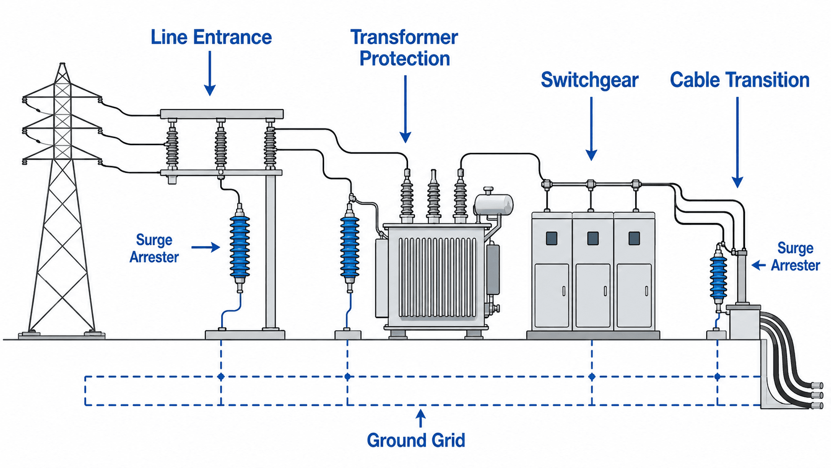
Surge arresters are installed where transient voltage is likely to enter a system, reflect, or concentrate at vulnerable insulation. The best location is usually close to the equipment terminal being protected.
| Location | Protected equipment | Why the location is important |
|---|---|---|
| Transformer terminal | Transformer winding and bushing insulation | Minimizes separation between arrester and critical insulation |
| Substation line entrance | Station bus and connected equipment | Intercepts incoming traveling-wave surges |
| Cable transition | Cable and termination insulation | Protects at a point where surge-wave impedance changes |
| Switchgear / equipment terminal | Internal insulation and connected apparatus | Keeps surge path close to sensitive equipment |
| Overhead line structure | Line insulation / outage performance | Reduces flashover probability at lightning-prone structures |
Swipe horizontally to view all table columns.
Why Arrester Lead Length and Grounding Matter
A properly selected arrester can still provide poor protection if it is installed with long looping leads or a high-impedance ground path. During a fast surge, lead inductance can add significant voltage between the protected terminal and ground.
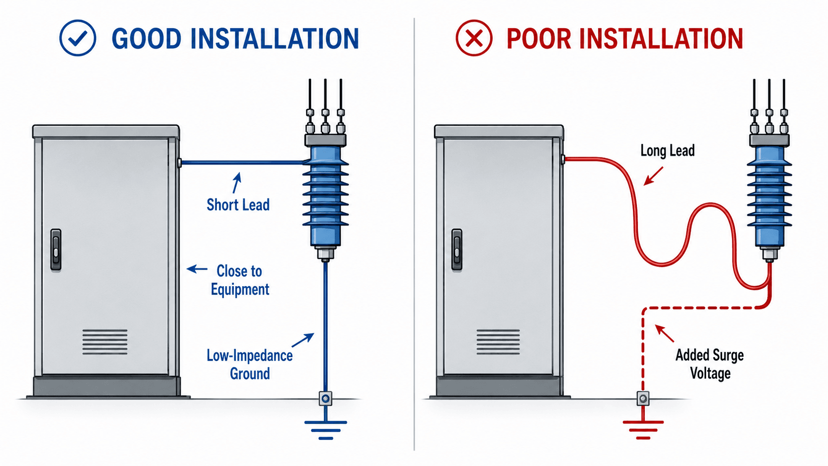
Lead Inductance
The extra lead voltage is related to how quickly surge current changes:
Lightning surges can have very high \(di/dt\), so even modest lead inductance can add meaningful voltage. This is why arrester leads should be short and direct.
Ground Path
The arrester should connect to a low-impedance grounding system. High pole-ground resistance, corroded connections, long grounding conductors, or poor station bonding can raise local ground potential and reduce protection effectiveness.
The equipment does not care how good the arrester looks on paper. It only experiences the actual terminal voltage produced by the arrester plus the installation.
Line Surge Arresters on Transmission and Distribution Lines
Line surge arresters are installed on overhead lines to reduce lightning-related flashovers and improve outage performance at selected structures or spans.
Applications include structures with high tower-footing resistance, poor shielding performance, high lightning exposure, compact insulation geometry, or critical reliability requirements. Line arresters can be non-gapped or externally gapped depending on the design.
| Problem | How a line arrester helps | Additional review |
|---|---|---|
| High backflashover rate | Limits voltage across line insulation during lightning current | Tower grounding, shielding, lightning density |
| Poor tower footing resistance | Provides additional surge-current path / voltage limitation | Grounding improvement may still be valuable |
| Critical corridor | Reduces lightning-caused trips at selected structures | Reliability benefit vs. maintenance/installation cost |
| Compact insulation | Improves margin where line insulation withstand is constrained | Arrester rating, energy duty, mechanical mounting |
Swipe horizontally to view all table columns.
See Transmission Lines and Distribution Lines for the surrounding line context.
Surge Arrester Failure Modes and Inspection Checks
Arresters can fail because of electrical overstress, thermal aging, moisture ingress, contamination, mechanical damage, or a poor installation that exposes the arrester to more stress than expected.
| Failure mode | Possible cause | What to inspect |
|---|---|---|
| Thermal runaway | Excess TOV, wrong MCOV, repeated energy duty | Heating, discoloration, failed disconnector, leakage-monitor trend |
| Moisture ingress | Seal failure, cracked housing, aging | Cracks, swelling, corrosion, abnormal leakage, tracking |
| External flashover | Pollution, salt, wet contamination, inadequate creepage | Surface tracking, arc marks, contamination bands |
| Ground-lead failure | Loose/corroded connection, mechanical damage | Ground continuity, conductor condition, lug integrity |
| Mechanical damage | Storm debris, wildlife, conductor strain, impact | Broken sheds, bent bracket, loose terminals |
| Protection underperformance | Long leads, wrong placement, weak ground path | Distance to protected terminal and actual surge-current path |
Swipe horizontally to view all table columns.
Surge Arrester Engineering Review Checklist
A complete review starts with system grounding and voltage, then checks protection margin, energy duty, physical installation, and long-term condition.
| Review item | Verify | Risk if missed |
|---|---|---|
| System grounding | Effectively grounded, resistance-grounded, ungrounded, resonant-grounded behavior | Unexpected phase-to-ground TOV |
| MCOV | Maximum normal phase-to-ground operating voltage | Arrester overheats in normal/abnormal service |
| TOV capability | Ground-fault and abnormal-voltage duration | Thermal runaway during temporary overvoltage |
| Protective level | Residual voltage vs. protected-equipment insulation withstand | Insufficient insulation margin |
| Energy duty | Lightning, switching, line length, capacitor-bank duty, repeat events | Internal thermal damage |
| Placement | Arrester physically close to protected terminal | Traveling-wave/lead voltage reduces protection |
| Lead length | Short, direct line and ground leads | Additional inductive voltage |
| Grounding | Low-impedance connection into station/pole grounding system | Local ground rise increases equipment stress |
| Environment | Pollution, salt, UV, wildlife, altitude, mechanical exposure | External insulation or housing deterioration |
| Condition monitoring | Leakage, counter, disconnector, visual and thermal condition | Deteriorating arrester remains in service unnoticed |
Swipe horizontally to view all table columns.
Surge Arrester Engineering References
- IEEE C62.11-2020 — Metal-Oxide Surge Arresters for AC Power Circuits (>1 kV) Active IEEE standard covering MOV surge arresters used to repeatedly limit voltage surges on AC power circuits above 1 kV; IEEE also has an active revision project underway.
- IEC 60099-4 — Metal-Oxide Surge Arresters Without Gaps for AC Systems Widely used international standard family for metal-oxide surge arresters in AC power systems.
- IEEE C62.22 — Application of Metal-Oxide Surge Arresters Application guidance for selecting and applying MOV surge arresters in electric power systems, including insulation coordination and system considerations.
Frequently Asked Questions
What does a surge arrester do?
A surge arrester limits transient overvoltage by conducting surge current to ground when system voltage rises above its protective region, helping protect transformer, cable, switchgear, and line insulation.
Is a surge arrester the same as a lightning arrester?
The terms are often used interchangeably, but surge arrester is the broader engineering term because arresters also limit switching and other transient overvoltages, not only lightning impulses.
What is MCOV on a surge arrester?
MCOV is the maximum continuous operating voltage the arrester can withstand continuously without excessive conduction or heating. It is a key value for matching the arrester to the system’s actual phase-to-ground operating voltage.
What is temporary overvoltage or TOV?
TOV is an abnormal power-frequency overvoltage that lasts much longer than a lightning impulse. Ground faults, neutral shift, load rejection, and other system conditions can create TOV stress that the arrester must survive.
What is residual voltage?
Residual voltage is the voltage that remains across the arrester while it conducts surge current. It is the protective level compared against the insulation withstand of the equipment being protected.
Where should a surge arrester be installed?
Usually as close as practical to the insulation being protected, such as transformer terminals, switchgear, cable transitions, line entrances, or exposed line structures, with short and direct leads to the conductor and grounding system.
Why does lead length matter on a surge arrester?
Fast surge current has high di/dt, so inductance in long leads can create additional voltage. Short, straight leads reduce that added voltage and improve the actual protection margin.
What causes a surge arrester to fail?
Common causes include wrong voltage rating, excessive TOV, repeated high-energy surges, moisture ingress, cracked housings, contamination, poor grounding, long leads, thermal aging, and mechanical damage.
Does a surge arrester protect against short circuits?
No. Surge arresters limit overvoltage. Fuses, circuit breakers, reclosers, and protective relays are used to detect and interrupt overcurrent and short-circuit conditions.
Summary and Next Step
Surge arresters protect electrical insulation by limiting transient overvoltage and diverting surge current into the grounding system. Their effectiveness depends on the MOV characteristic, MCOV, TOV capability, residual voltage, energy duty, and—just as importantly—the way the arrester is physically installed.
The strongest design habit is to treat surge arresters as part of the complete insulation-coordination system. Verify the source of the surge, the system grounding, the protected equipment’s insulation withstand, arrester protective level, lead length, ground path, and environmental duty together.