Key Takeaways
- Definition: A strip foundation is a continuous footing that spreads wall or line loads into soil along its length.
- Use case: It is commonly used below load-bearing walls, basement walls, and other linear support conditions in low- to mid-rise work.
- Main decision: The real judgment is whether bearing pressure, eccentricity, settlement, groundwater, frost, or constructability controls the footing size and detail.
- Outcome: After reading, you should understand the selection logic, core checks, practical limitations, and the situations that push engineers toward alternatives.
Table of Contents
Introduction
In brief: Strip foundations are continuous shallow footings used under walls or line loads to spread load safely into near-surface soil while limiting bearing pressure and settlement.
Who it’s for: Students, FE/PE prep, and foundation designers.
For informational purposes only. See Terms and Conditions.
In practice, strip foundation design is rarely just a width calculation. Soil variability, wall eccentricity, drainage, frost, adjacent excavation, and settlement often matter as much as the nominal bearing value.
Strip foundations infographic
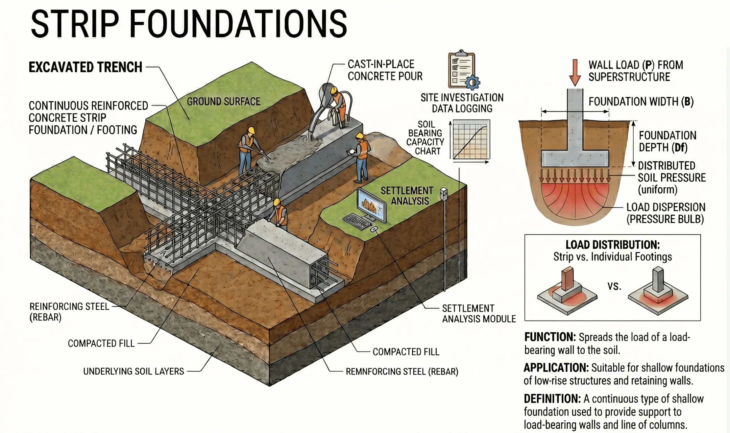
Notice the relationship between wall load, footing width, embedment, and the soil zone directly beneath the base. That simple geometry drives the first pass of design, but groundwater, settlement, eccentric loading, and construction disturbance often decide whether the concept actually works in the field.
What is a strip foundation?
A strip foundation, also called a continuous footing, is a shallow foundation that runs continuously under a load-bearing wall or other linear line load. Instead of carrying one concentrated reaction like a pad footing, it distributes load along a long strip of soil contact, making it a natural fit for wall-supported structures.
The concept sounds simple, but the engineering decision is not. The footing must be wide enough that the contact pressure stays within acceptable limits, deep enough to satisfy frost and durability requirements, and proportioned so the resulting stress distribution does not create excessive eccentricity, overturning tendency, sliding risk, or differential settlement.
Strip foundations are especially common in low-rise construction, masonry wall support, basement walls, and linear structural elements where columns are absent or closely spaced enough that a continuous support line is more logical than isolated footings. They are usually economical when the near-surface ground is reasonably competent and predictable.
They are not automatically the right answer just because a wall exists. Where soils are compressible, expansive, loose, uncontrolled, frost-susceptible, or strongly affected by groundwater, the engineer may need to widen the footing substantially, improve the subgrade, stiffen the supported wall, or select a different foundation type altogether.
Core principles, variables, and units
Strip foundation design begins with a few physical ideas: load must travel from the wall into the footing, then into the soil; the resulting soil pressure must remain acceptable; the wall-footing system must remain stable; and total as well as differential movement must stay within tolerable limits.
What engineers usually check first
On a first pass, engineers usually estimate the vertical service load per unit length of wall, choose a trial footing width, and compare average contact pressure against allowable support criteria or a limit-state check. That quick sizing step is useful, but it is only the beginning. Eccentricity, nearby excavations, wall moments, groundwater, and layered soils can all change the pressure pattern materially.
Key variables and typical ranges
The exact symbols vary by office, code base, and calculation style, but the same physical quantities appear again and again: wall load, footing width, embedment depth, allowable soil pressure, eccentricity, settlement, and any lateral actions that affect the wall or footing. A good designer always sanity-checks both units and physical meaning before trusting a result.
- P Vertical load per unit length of wall, often expressed as kN/m or kip/ft.
- B Footing width measured perpendicular to the wall, commonly in mm, m, in, or ft.
- Df Embedment depth to footing base, which affects frost protection, confinement, scour vulnerability, and constructability.
- q Average or actual soil contact pressure beneath the base, usually in kPa, psf, or ksi depending on context.
- qallow Allowable bearing pressure or equivalent allowable support criterion used for service-level sizing.
- e Eccentricity of the resultant from the footing centerline; often a critical stability and pressure-distribution check.
- s Estimated total settlement, with differential settlement often more important than the absolute value.
Do not let a single “allowable soil pressure” number hide the real problem. A strip footing can satisfy a bearing check and still perform poorly if wall eccentricity, adjacent cuts, groundwater softening, or differential settlement were not evaluated.
Decision logic and design workflow
The best strip foundation workflow moves from site understanding to geometry, then to performance checks. That order matters because footing width is not just a structural number; it is a geotechnical, durability, drainage, and construction decision at the same time.
Step 1: Confirm the supported element is truly a wall or line load, not an isolated reaction better handled by a pad foundation.
Step 2: Review subsurface conditions near founding level, including fill quality, groundwater, soft seams, expansive soils, frost susceptibility, and nearby utilities.
Step 3: Estimate service and factored wall reactions per unit length, including any eccentricity, lateral actions, or moment transfer from the supported wall.
Step 4: Select a trial width and embedment depth, then check contact pressure, eccentricity, sliding, overturning tendency where relevant, and settlement.
Step 5: Refine reinforcement, detailing, drainage, and construction notes so the design remains buildable and robust when field conditions vary slightly from the idealized section.
This workflow is also where the engineer decides whether the footing is still the right system. If width becomes excessive, if the wall crosses variable soils, or if movement-sensitive construction sits above the footing, an alternative like a mat foundation, ground improvement, or deep support may become more rational.
Equations and calculations
For preliminary sizing, the most common first check is average pressure under the footing. The basic idea is simple: divide service load per unit length by footing width. Then refine the pressure model if eccentricity or moment alters the distribution.
Here, \(q_{avg}\) is the average soil contact pressure, \(P\) is the vertical load per unit length of wall, and \(B\) is the footing width. In practice, this quick relationship helps choose a trial width, but the final answer must reflect the actual resultant location and whether the pressure remains compressive over the full base.
When a wall load is eccentric or a moment reaches the footing, the resultant shifts by \(e\). A common rule of thumb is to keep the resultant within the middle third so the base remains fully in compression. That often appears as:
If the resultant moves outside that middle-third limit, part of the base may lift off in simple elastic interpretation, and the pressure distribution becomes triangular rather than broadly uniform or trapezoidal. That does not automatically mean the footing is impossible, but it does mean the engineer must stop treating the footing like a centered strip under pure axial load.
What controls the calculation quality
The equations themselves are not the difficult part. The difficult part is deciding which load case governs, whether the soil support criterion is service-based or limit-state based, how realistic the soil profile is, and whether settlement rather than bearing capacity actually controls. Good strip footing calculations are judgment-heavy even when the algebra is light.
Worked example
Example: preliminary strip footing sizing for a masonry wall
Assume a load-bearing wall produces a service reaction of \(P = 120 \text{ kN/m}\). The geotechnical recommendation permits an allowable service pressure of \(q_{allow} = 180 \text{ kPa}\) for the founding stratum, subject to settlement review. A first-pass width estimate is:
That suggests a trial width of about 700 mm. But that is not yet a finished design. The engineer would next check whether the wall load is centered, whether the footing needs projection for masonry detailing, whether the base is below frost depth, whether adjacent basement excavation changes effective confinement, and whether the settlement estimate remains acceptable if soil conditions vary along the wall length.
Now suppose the wall also delivers a moment that creates an eccentricity of \(e = 0.16 \text{ m}\). With a 700 mm footing, the middle-third limit is \(B/6 = 0.117 \text{ m}\). Since the eccentricity exceeds that value, the initial footing is no longer behaving like a centered compression-only base. The design response could be to widen the footing, reduce eccentricity through geometry, revise wall detailing, or reconsider the support system.
This example shows why strip footing design should not end with one division step. A preliminary width may look acceptable on bearing, yet become marginal once wall moments, offsets, or field variability are included.
Engineering judgment and field reality
Strip foundations are one of the easiest foundation types to oversimplify. In design spreadsheets they look neat because the load is often expressed per unit length and the footing geometry is repetitive. In the field, however, the line of support may cross patched fill, old utility trenches, variable moisture zones, expansive clay pockets, weathered lenses, or soft seams that never appeared clearly in borings.
Long walls are particularly sensitive to variability because they bridge across changing conditions. One local soft pocket may not trigger a global bearing failure, but it can create a hinge point for differential movement, cracking, or door and façade distress. For that reason, proof-rolling observations, excavation inspection, undercut criteria, and rapid response language in the geotechnical recommendations matter more than many designers initially expect.
Groundwater also changes the answer. A footing detail that looks fine in dry-season borings may behave differently when seasonal perched water softens the bearing surface, changes excavation stability, increases pumping requirements, or complicates concrete placement and subbase preparation. The same is true for frost-susceptible zones and expansive clays, where the issue is not only strength but long-term movement and volume change.
The most reliable strip footing recommendations are paired with explicit construction observations: verify founding stratum, remove unsuitable pockets, protect the base from disturbance and water, and stop work if actual soil conditions differ materially from the assumed profile.
Where this method breaks down
Strip foundations stop being the easy answer when one or more of the core assumptions fail. The first common breakdown is weak or highly compressible near-surface soil. Even if ultimate failure is not imminent, the footing may need to become so wide that the excavation, concrete quantity, and wall detailing become inefficient compared with a mat or another system.
A second breakdown occurs where the wall is heavily eccentric, strongly laterally loaded, or located near an excavation or slope. In those cases, simple symmetric pressure assumptions no longer represent actual behavior well. Sliding, overturning tendency, or nonuniform stress may dominate.
A third breakdown is movement-sensitive construction over variable soils. Long, relatively stiff walls over alternating firm and soft zones can experience cracking even when average bearing stress looks acceptable on paper. Where expansive soils, loose fill, peat, uncontrolled backfill, or seasonal wetting-drying effects are present, designers often need a more robust strategy than a standard continuous footing detail.
Finally, strip foundations become less dependable where construction control is weak. If the founding level is left exposed too long, remolded by rain, overexcavated without proper replacement, or built across poorly characterized fill, the built system may not resemble the engineered assumption set at all.
Common pitfalls and engineering checks
- Using one bearing value without checking whether settlement is actually the controlling criterion.
- Ignoring wall eccentricity, offsets, or moment transfer into the footing.
- Assuming the same soil support along the entire wall length when the profile is obviously variable.
- Placing the footing too shallow for frost, moisture fluctuation, erosion, or utility conflicts.
- Failing to specify subgrade protection, drainage, and inspection requirements during construction.
One of the most expensive strip footing mistakes is treating a continuous wall footing as though every meter of wall bears on identical soil. Long linear foundations magnify small local defects into visible serviceability problems.
Before issuing the design, ask four questions: Is the resultant realistically centered? Does settlement govern more than bearing? Will actual excavation conditions match the borings closely enough for this detail to be robust? And if the field reveals weaker material, is there a clear undercut-and-replace path already specified?
| Parameter | Symbol | Typical units | Why it matters |
|---|---|---|---|
| Wall load per unit length | P | kN/m, kip/ft | Sets first-pass sizing demand for the footing width. |
| Footing width | B | mm, m, in, ft | Controls average pressure, eccentricity limit, and construction footprint. |
| Allowable pressure | qallow | kPa, psf | Provides the starting serviceability-based sizing criterion. |
| Eccentricity | e | mm, m, in, ft | Changes pressure distribution and can trigger uplift over part of the base. |
| Total settlement | s | mm, in | Often more important to performance than the ultimate bearing margin. |
Relevant standards and design references
Strip foundation design usually draws from both geotechnical and structural references. The exact governing documents vary by jurisdiction and project type, but the following categories are commonly relevant:
- IBC and local building code adoption: Establishes the overall legal framework for shallow foundation design, frost depth considerations, and soil-related reporting requirements on many building projects.
- ACI 318: Governs reinforced concrete design and detailing where the strip footing is reinforced and must be checked for flexure, shear, development, and durability-related detailing.
- ASCE 7: Helps define gravity, lateral, seismic, and load combination demands that can affect footing reactions and eccentricity.
- Project geotechnical report: Usually provides the actual bearing, settlement, excavation, groundwater, subgrade preparation, and observation recommendations that control the footing in the field.
- Agency or project-specific earthwork specifications: Critical for undercut criteria, fill compaction, proof-rolling, dewatering, and acceptance of the founding surface.
On many jobs, the geotechnical report is the most directly useful design reference because it translates raw soil conditions into project-specific recommendations. Code tells you what must be checked; the geotechnical recommendations tell you what the ground is likely to allow.
Frequently asked questions
A strip foundation supports a continuous wall or line load, while a pad foundation supports an isolated concentrated reaction, usually from a column. Strip footings are typically chosen where support is linear and continuous, whereas pad footings are usually better for discrete support points.
They are usually a strong option when wall loads are moderate, the founding soil near the surface is reasonably competent and uniform, groundwater is manageable, and predicted settlement remains acceptable for the supported structure.
The controlling issue is often a combination of bearing pressure, eccentricity, settlement, wall geometry, frost depth, and field conditions rather than one single formula. On real projects, movement and constructability often govern as much as strength.
They become less attractive when near-surface soils are weak, variable, expansive, highly compressible, or heavily influenced by groundwater, or when the required width and detailing become so large that a mat, deep foundation, or ground improvement approach is more rational.
Yes. A footing can satisfy a nominal bearing check and still perform poorly if settlement, differential movement, construction disturbance, frost action, expansive soil behavior, or wall eccentricity were not handled appropriately in the final design and field execution.
Summary and next steps
Strip foundations are one of the most common shallow foundation systems because they match the geometry of wall-supported construction and often provide a simple, economical way to spread line loads into the ground. But good strip footing design is not just about dividing load by width. It is about understanding what actually controls the performance of the supported wall-soil system.
In real projects, the governing issue may be average bearing pressure, but it may just as easily be settlement, differential movement, eccentricity, frost depth, groundwater, or excavation disturbance. The best designs stay simple without being simplistic: they use clean first-pass sizing, then add the field judgment and detailing needed for the footing to perform as built, not just as calculated.
If you are learning shallow foundation design, strip footings are a strong topic because they connect geotechnical behavior, reinforced concrete detailing, and real construction decision-making in one system. They are simple enough to understand quickly and rich enough to teach good engineering habits.
Where to go next
Continue your learning path with these curated next steps.
-
Compare with pad foundations
Useful when the next decision is whether your support condition is truly continuous or better treated as isolated column support.
-
Study settlement analysis
A strong next step when movement may govern more than ultimate soil strength.
-
See when mat foundations become more efficient
Helpful when strip or pad footings become too wide, too numerous, or too sensitive to variable support conditions.