Key Takeaways
- Definition: Shallow foundations transfer structural load into near-surface soil using footings or mats rather than deep elements such as piles.
- Use case: They are usually preferred when competent bearing soil exists close to grade and settlement can be kept within project tolerances.
- Main decision: The core design question is not just “Can the soil carry the load?” but “Can the footing system do so with acceptable settlement, rotation, excavation risk, and construction practicality?”
- Outcome: After reading, you should understand when shallow foundations make sense, what checks control the design, and when to switch to ground improvement, mats, or deep foundations.
Table of Contents
Introduction
Direct answer: Shallow foundations are footings or mats that support a structure by spreading load into soil close to the ground surface. They are used when near-surface soils have adequate bearing capacity and expected settlement is acceptable, making them a practical and economical alternative to piles or other deep foundation systems.
This page is for engineering students, FE and PE exam candidates, and practicing engineers who want a clear framework for understanding shallow foundations. Instead of treating the topic as one formula, this guide explains how engineers actually make the decision: define the soil profile, estimate loads, check bearing and settlement, consider groundwater and excavation constraints, and then select the footing type that performs well in the field.
The dominant search intent here is a mix of definition, design application, decision-making, and practice-oriented workflow. That means the most useful page is not a generic overview. It is a page that shows where shallow foundations fit within the broader geotechnical workflow and what usually controls the final answer on real jobs.
Shallow foundations infographic
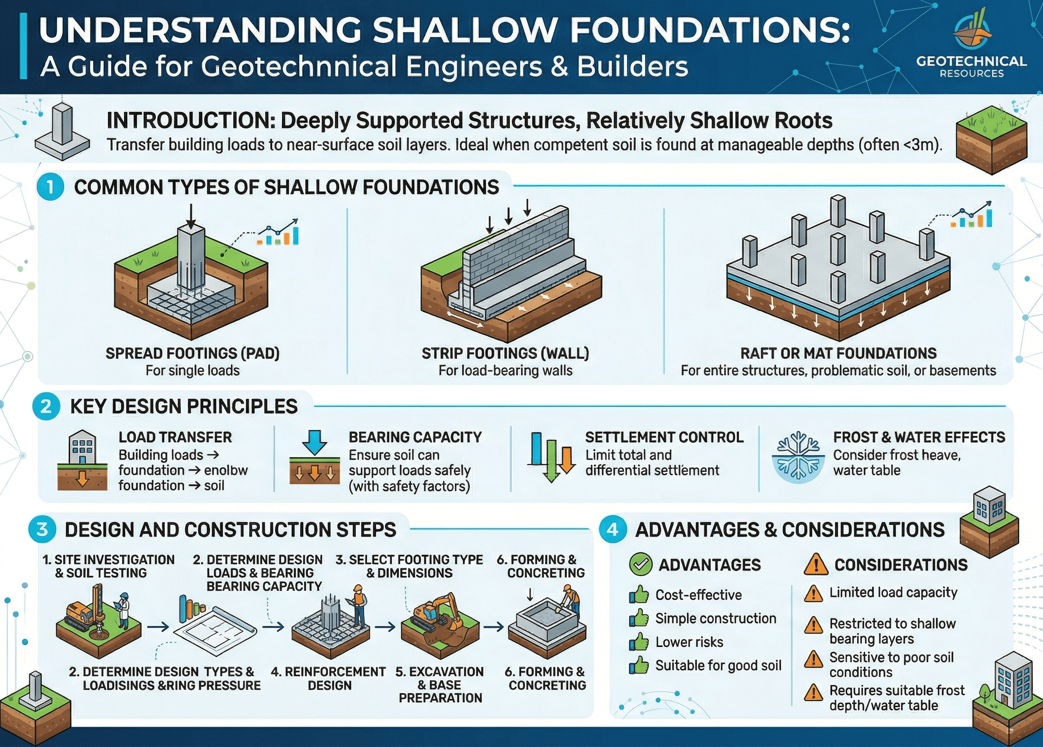
The first thing to notice is that shallow foundation design is a balance problem. The footing must spread load enough to keep soil pressure acceptable, but the site must also tolerate the resulting settlement, excavation depth, groundwater condition, and construction sequence. That is why footing choice is often driven by the whole system rather than by one bearing-capacity number.
What are shallow foundations?
Shallow foundations are foundation systems that deliver structural loads into soils located relatively close to the ground surface. In practical terms, they include spread or pad footings, strip footings, combined footings, and larger mats or rafts when those systems still behave as near-surface load-spreading elements rather than deep load-transfer elements.
The goal is simple: spread concentrated column or wall loads over enough plan area that the supporting soil does not fail in shear and does not settle more than the structure can tolerate. That sounds straightforward, but the engineering challenge is that soil is not a uniform material. Stiffness changes with depth, moisture, density, stress history, and groundwater. A footing that looks adequate on paper can perform poorly if the subsurface profile is variable or if construction changes the condition of the founding level.
In building work, shallow foundations are often the most economical starting point because they are fast to construct, easy to inspect, and compatible with many low- to mid-rise structures. They also integrate naturally with concrete footings, grade beams, slabs, and retaining interfaces. For that reason, shallow foundations are often the first option considered before a project escalates to a deeper or more specialized system.
To understand the broader context, it helps to connect this topic to Foundation Design and the underlying soil behavior described in Soil Mechanics. Those pages provide the bigger picture; this page focuses on how shallow foundation decisions are made.
Types of shallow foundations and how engineers choose between them
Engineers do not choose a footing type by tradition alone. They match the footing to the load path, structural spacing, available footprint, subsurface condition, and allowable movement. The most common types include:
Pad or isolated footings
These support individual columns and are common when column spacing is generous and loads are moderate. They work best when a reasonably uniform bearing layer is available and the plan footprint can be sized without running into property lines, utilities, or neighboring footings. For a deeper dive, see Pad Foundations.
Strip footings
Strip foundations are continuous footings beneath load-bearing walls or lines of closely spaced columns. They are frequently used for walls, basements, and lighter building lines where load is distributed along length rather than concentrated at one point. They are covered in more detail on the Strip Foundations page.
Combined footings
Combined foundations support two or more columns on one footing when separate footings would overlap or when an edge column near a property line would otherwise cause eccentric loading. The system lets the engineer position the resultant within the effective base area more efficiently. See Combined Foundations for the geometry and load-path considerations.
Mat and raft foundations
When column spacing tightens, loads increase, or differential settlement becomes more important than isolated footing economy, a mat or raft can be the better system-level answer. These foundations distribute building loads over a large area and can improve settlement performance by averaging spatial variability. Relevant next-step pages include Mat Foundations and Raft Foundations.
If isolated footings start to overlap, or if differential settlement between neighboring supports becomes the dominant risk, stop optimizing each footing separately and evaluate whether a combined or mat solution is more rational.
Core principles, variables, and units
The key variables behind shallow foundation design are not limited to footing size. The behavior depends on load magnitude, footing shape, embedment depth, soil strength, soil stiffness, groundwater condition, and how variable the profile is across the site.
Key variables and typical ranges
A useful sanity check is to separate variables that mostly affect ultimate capacity from variables that mostly affect serviceability. Strength parameters such as cohesion and friction angle influence shear capacity, while compressibility and modulus govern settlement. Many design mistakes happen when one is checked carefully and the other is treated as an afterthought.
- \(B\) Footing width or characteristic plan dimension; commonly ft or m. Increasing \(B\) usually lowers average contact stress but can increase total settlement depending on soil profile.
- \(D_f\) Embedment depth of foundation base below grade; commonly ft or m. Influences confinement, surcharge, frost considerations, and excavation effort.
- \(q\) Applied or contact pressure at the foundation-soil interface; commonly ksf, psf, kPa, or kN/m².
- \(c’\) Effective cohesion for drained analysis, often near zero for clean sands and larger for some clays, though engineers should use site-specific values from the geotechnical model.
- \(\phi’\) Effective friction angle, usually in degrees. It strongly influences bearing factors and should be based on defensible soil characterization, not guesswork.
- \(\gamma\) Unit weight of soil; commonly pcf or kN/m³. Groundwater can reduce effective unit weight and change the stress state significantly.
- \(S\) Settlement, usually in inches or mm. Total and differential settlement are often more important to performance than the raw ultimate capacity value.
Before trusting any footing calculation, confirm which soil parameters are drained, undrained, effective-stress, or total-stress values and whether the load case and construction stage match those assumptions.
Decision logic and design workflow
The best shallow foundation workflow starts with the ground model rather than the footing shape. Engineers first ask whether competent support exists near the surface, then whether settlements are acceptable, and only then optimize geometry and reinforcement.
1) Define structure loads and tolerable movement. 2) Establish subsurface profile and groundwater from investigation data. 3) Screen whether near-surface soils can support shallow foundations. 4) Select a footing family based on structural layout. 5) Check bearing, eccentricity, sliding where relevant, and settlement. 6) Revisit constructability, neighboring foundations, excavation stability, and drainage. 7) If risk remains high, consider ground improvement, a mat or raft, or a deep foundation alternative.
This workflow is why Settlement Analysis and Ground Improvement often become part of the same conversation. A shallow footing is not selected in isolation. It is selected because it is the best balance of performance, cost, and buildability for the actual site.
Bearing, pressure distribution, and settlement checks
One of the best-known starting equations for shallow foundations is the Terzaghi-style bearing expression for a strip footing under idealized conditions. It helps explain how cohesion, surcharge, width, and unit weight contribute to ultimate bearing capacity.
Here, \(q_{ult}\) is ultimate bearing capacity, \(c’\) is effective cohesion, \(\gamma\) is unit weight, \(D_f\) is embedment depth, \(B\) is footing width, and \(N_c\), \(N_q\), and \(N_{\gamma}\) are bearing-capacity factors related primarily to friction angle. In real design, the exact expression may be modified for shape, load inclination, eccentricity, groundwater, local code approach, or service-level reporting from the geotechnical engineer.
Many workflows then compare actual service contact pressure with allowable bearing pressure, or convert ultimate capacity to allowable form using a factor of safety:
But this is only part of the story. A shallow foundation that satisfies bearing can still be unacceptable if it settles too much or settles unevenly. That is why stress distribution and deformation compatibility matter. On compressible clays, loose sands, uncontrolled fill, or variable residual soils, serviceability often governs long before a classical shear failure mechanism does.
Treating “allowable bearing pressure” as permission to ignore settlement is one of the most expensive misunderstandings in geotechnical practice. Always ask what movement criteria were assumed when the allowable value was developed.
Worked example: screening a column footing
Example
Consider a building column carrying a service load of 240 kips on a site where the geotechnical report indicates an allowable net bearing pressure of 4 ksf at the proposed founding level, with the note that total settlement should remain acceptable if footing widths stay within the screened range and subgrade preparation is controlled. A first-pass footing area is:
A square footing would therefore have a side length of about \(\sqrt{60} \approx 7.75\) ft, so an engineer might trial an 8 ft by 8 ft footing. That gives an average service pressure of:
At first glance, that seems acceptable because the average pressure is below the screened allowable value. But the design is not finished. The engineer still needs to verify load eccentricity, confirm that nearby footings will not overlap, review settlement sensitivity to local fill or soft layers, coordinate footing thickness and punching shear with the structural designer, and check whether groundwater or overexcavation could weaken the founding surface during construction.
That is what makes this a realistic example. The math is quick, but the decision is broader than one division step.
Engineering judgment and field reality
The field rarely gives you the perfect founding surface assumed in a hand calculation. Excavation may expose fill, desiccated clay, loose seams, organics, seepage, or soft pockets that were not obvious in borings. Rain can disturb the base. Construction traffic can rut the excavation. Concrete placement may be delayed, leaving the subgrade exposed longer than intended. These issues matter because shallow foundations depend directly on the condition of the soil you actually found, not the soil you hoped was there.
Experienced engineers watch for abrupt changes in soil type across a footing line, softening from groundwater infiltration, overexcavation that gets backfilled loosely, and local stress concentrations from eccentric columns, wall offsets, or adjacent utilities. They also recognize when a geotechnical recommendation was developed for one construction sequence but the contractor is building under different site constraints.
A footing founded on “competent soil” is only as reliable as the last few inches of prepared bearing surface. Proofrolling, undercut decisions, moisture control, and observation at the time of excavation can change the performance outcome more than a small theoretical refinement in the bearing equation.
This is also where geotechnical judgment overlaps with earthwork quality. On some sites, modest subgrade improvement or tighter excavation control can preserve a shallow-foundation concept that would otherwise fail. On other sites, trying too hard to force shallow foundations onto weak or highly variable ground simply shifts cost into rework and claims.
When this method breaks down
Shallow foundations stop being the right answer when the core assumptions behind near-surface support are no longer valid. That includes sites with thick compressible clay, loose uncontrolled fill, collapsible soils, peat, aggressive groundwater, highly variable weathered rock surfaces, or very high loads that would force footings to become excessively large or sensitive to differential settlement.
The method also breaks down when site geometry works against it. Property-line constraints may create intolerable eccentricity. Dense utility corridors may make footing placement impractical. Deep basements or adjacent excavations can alter the stress field and founding conditions. In seismic or liquefaction-prone settings, the near-surface zone may not offer dependable support without mitigation.
At that point, the correct response is not to keep stretching the footing. The correct response is to change the system. That may mean using Ground Improvement, shifting to a Mat Foundation or Raft Foundation, or moving decisively to Pile Foundations.
Common pitfalls, design tradeoffs, and engineering checks
- Using generic soil parameters instead of values tied to the actual site profile and load case.
- Checking bearing capacity carefully while barely evaluating total and differential settlement.
- Ignoring groundwater changes between investigation and construction.
- Assuming a footing can be enlarged indefinitely without consequences for excavation, overlap, or adjacent structures.
- Forgetting that structural and geotechnical design are linked through punching shear, stiffness, and load eccentricity.
A very common misuse is applying one allowable bearing value across the whole site even though fills, soft zones, or depth-to-bearing changes clearly vary between support locations.
| Design issue | What usually controls | Typical units | Why it matters |
|---|---|---|---|
| Bearing pressure | Applied load versus allowable or factored capacity | ksf, psf, kPa | Governs minimum plan area and whether near-surface soil is viable. |
| Total settlement | Soil stiffness, compressibility, stress increase, layer thickness | in, mm | Often governs serviceability even when bearing capacity looks acceptable. |
| Differential settlement | Soil variability and structural spacing | in, mm, slope ratio | Controls cracking, alignment, and superstructure performance. |
| Embedment depth | Frost, scour, topsoil removal, confinement, utilities | ft, m | Affects both geotechnical performance and construction practicality. |
| Groundwater | Seasonal water level and seepage condition | ft below grade, m below grade | Changes effective stress, excavation stability, and founding-surface quality. |
One helpful tradeoff question is this: is the project trying to minimize concrete quantity, minimize risk, or minimize long-term movement? The cheapest isolated footing layout is not always the cheapest project once rework, schedule disruption, and tolerance issues are included.
Visualizing shallow foundation selection
A useful mental model is to picture three layers of decisions stacked on top of each other. The structure decides where the loads enter the ground, the geotechnical profile decides how those loads spread and compress the soil, and the construction process decides whether the assumed founding condition is actually achieved in the field.
That is why shallow foundation design is best visualized as a map rather than a single check: plan geometry at the surface, stress bulbs extending downward, groundwater cutting across the profile, and neighboring footings or walls interacting with each other. Once readers see the problem that way, footing choice becomes much more intuitive.
Relevant standards and design references
The exact standard set varies by project type and jurisdiction, but shallow foundation work is commonly anchored by the following reference families:
- IBC and local building code provisions: Used for foundation design requirements, load combinations through referenced structural standards, frost depth rules, and jurisdiction-specific geotechnical expectations.
- ACI 318: Governs structural concrete footing design, including flexure, shear, punching shear, development, and detailing once the geotechnical footing geometry is established.
- ASCE 7: Provides load determination and combinations that influence footing reactions and required design checks.
- FHWA geotechnical manuals: Useful for practical guidance on spread footings, settlement, site characterization, and foundation selection on transportation and public works projects.
- Project geotechnical report and agency supplements: These are the source-of-truth documents for site-specific allowable values, settlement criteria, subgrade preparation, undercut guidance, and groundwater-related recommendations.
In practice, the best workflow is to use published standards for methodology and detailing, but let the project geotechnical recommendations control the site-specific design assumptions.
Frequently asked questions
Shallow foundations spread structural load into soils close to the surface, while deep foundations transfer load to deeper support layers using elements such as piles or drilled shafts. The choice depends on near-surface soil quality, settlement tolerance, groundwater, load magnitude, and whether excavation-based construction is practical and low-risk.
In many real projects, settlement or differential settlement controls before classical bearing failure does. A footing may satisfy an allowable bearing check and still create serviceability problems if compressible soils, loose fill, or variable subsurface conditions are present.
They become poor candidates when competent near-surface support is absent, settlements are excessive, excavation is unstable, groundwater is problematic, or structural loads force impractically large footing sizes. In those cases, ground improvement, mats, rafts, or deep foundations are usually worth evaluating.
Yes, mats and rafts are generally considered shallow foundations because they still transfer load into soil near the ground surface rather than relying on deep shafts or piles. They are often chosen when isolated footings would overlap or when differential settlement control is more important than minimizing concrete volume.
The footing base should be checked for correct elevation, bearing-surface uniformity, unexpected soft or wet zones, overexcavation, groundwater seepage, and compliance with any geotechnical recommendations for undercut, recompaction, or proofrolling. Those field observations often matter as much as the office calculations.
Summary and next steps
Shallow foundations are one of the most common and economical foundation systems in geotechnical engineering, but they only work well when the near-surface ground can support the load with acceptable movement. That means the real design problem is broader than choosing a footing size. Engineers must connect loads, subsurface conditions, groundwater, settlement tolerance, and construction realities into one coordinated decision.
The biggest practical lesson is that shallow foundation design is rarely controlled by one perfect equation. Bearing capacity matters, but field preparation, subsurface variability, and settlement behavior often decide whether the foundation actually performs well. Good design is therefore a combination of calculation, site characterization, and disciplined construction observation.
Where to go next
Continue your learning path with these closely related geotechnical topics.
-
Read a deeper dive on Bearing Capacity
Useful when you want to understand the strength side of footing design in more detail.
-
Study Settlement Analysis next
The best follow-on topic when serviceability and differential movement are the real design drivers.
-
Compare with Pile Foundations
Helpful when shallow support becomes too risky, too flexible, or too large to remain practical.