Key Takeaways
- Definition: A bearing capacity test evaluates how much pressure soil or improved ground can support before excessive settlement or shear failure becomes unacceptable.
- Use case: It is used when engineers need direct field evidence for shallow foundation support, proof of ground improvement, or confirmation of uncertain subsurface assumptions.
- Main decision: The key judgment is whether the test result truly represents the future footing conditions, not just whether one loaded pad performed well on test day.
- Outcome: After reading, you should understand the workflow, the major variables, the interpretation logic, and the limits of using a test result in design.
Table of Contents
Introduction
In brief: A bearing capacity test applies controlled load to the ground so engineers can judge whether soil support is limited by shear failure, excessive settlement, or both.
Who it’s for: Students, FE/PE prep, and practicing engineers.
For informational purposes only. See Terms and Conditions.
This page explains what a bearing capacity test actually tells you, how it differs from a paper calculation, and where experienced engineering judgment matters more than the raw test number.
Bearing Capacity Test infographic
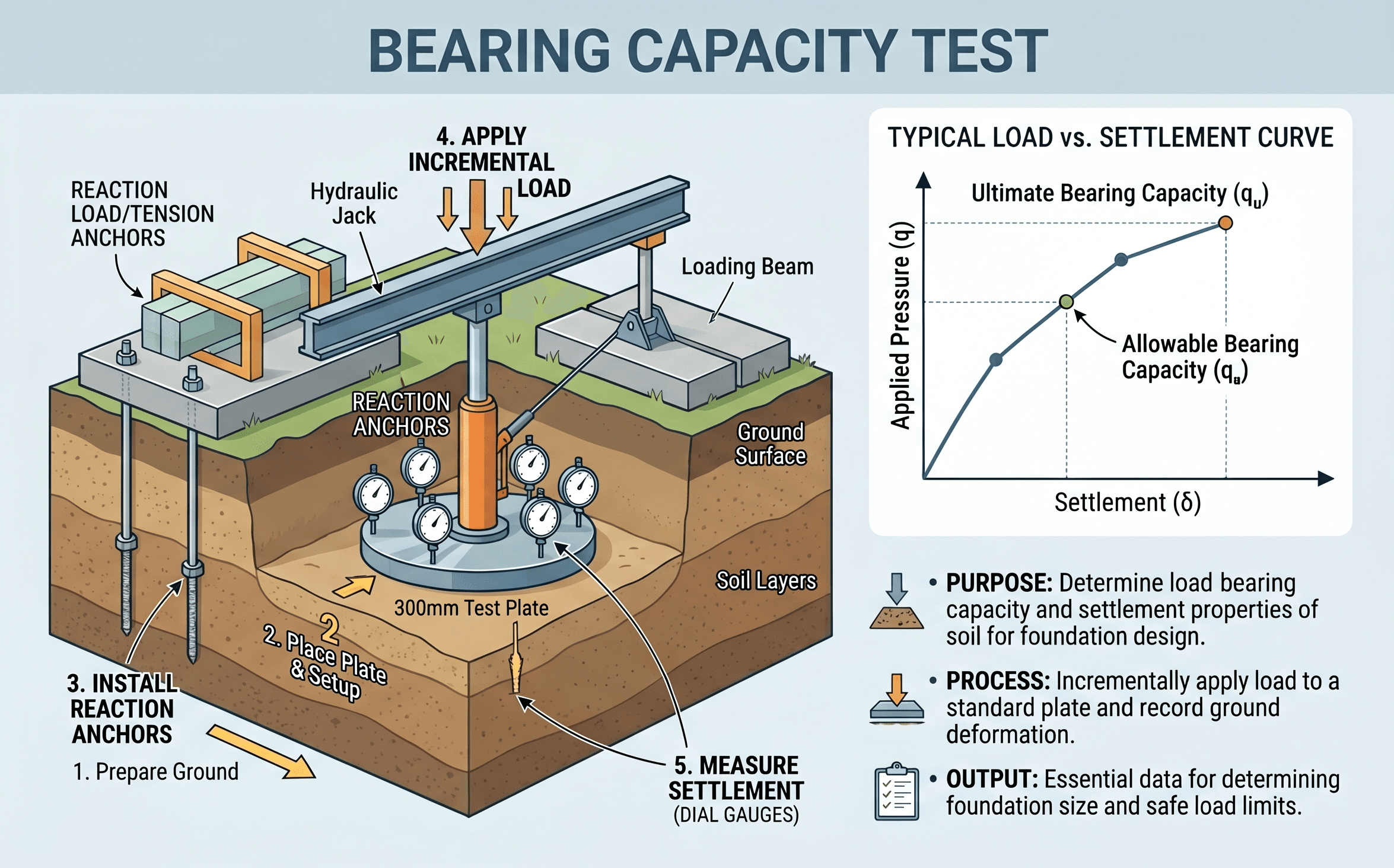
Notice the relationship between applied pressure, measured settlement, and the inferred failure or serviceability limit. In practice, the most important question is not only how high the curve goes, but how early settlement accelerates and whether the tested zone matches the real foundation footprint.
What is a bearing capacity test?
A bearing capacity test is a field loading procedure used to evaluate how the ground responds when a known load is applied through a plate, pad, or other test element. In geotechnical engineering, the goal is usually to estimate whether the soil can safely support a planned shallow foundation or whether ground improvement is performing as intended.
The phrase sounds simple, but engineers often mean two slightly different things when they say it. Sometimes they mean a true plate load test or field load test that produces a pressure-settlement curve. In other cases, they use the phrase more loosely for a site verification activity that supports allowable bearing pressure recommendations. Either way, the key output is not just “pass” or “fail.” The real value is understanding the relationship between stress, settlement, and the failure mechanism that begins to form under load.
This matters because foundations are rarely controlled by only one limit state. A footing may have plenty of theoretical ultimate capacity and still be unacceptable if settlements are too large. On the other hand, a stiff granular soil may show very small settlements until the pressure climbs rapidly near a punching or general shear failure condition. A useful bearing capacity test helps engineers understand where that practical limit lies for the project at hand.
Core principles, variables, and units
The test is built around one basic idea: load applied over area creates contact pressure, and the ground responds by deforming and mobilizing shear resistance. Engineers track both the applied pressure and the resulting settlement because a safe design depends on how the soil gets there, not just on the highest pressure reached.
Key variables and typical ranges
Exact numbers vary with soil type, footing size, test method, and project tolerance for movement, but the same core variables appear in nearly every bearing capacity test interpretation.
- q Applied contact pressure, usually reported in kPa, MPa, psf, or ksi depending on the project.
- P Applied load from jack or reaction system, often in kN, kip, or ton-force.
- A Loaded area of the plate or test footing. Small test areas often produce different behavior than full-scale footings.
- s Measured settlement or deflection, usually in mm or inches. This is often the most decision-critical field reading.
- B Plate or footing width. Scale effects matter because failure geometry changes with loaded width.
- \(\gamma\) Unit weight of soil, important when comparing test findings to theoretical bearing capacity calculations.
- \(\varphi, c, c_u\) Strength parameters used in theory checks or back-analysis: friction angle, cohesion, or undrained shear strength.
- WT Groundwater condition, which can change effective stress, stiffness, and the interpretation of observed behavior.
In most tests, engineers want a clean pressure-settlement curve with stable load increments, enough hold time to observe short-term creep or seating effects, and instrumentation set far enough from the loaded area that the reaction system does not contaminate the readings.
Always compare the test plate size and stress distribution with the actual foundation geometry. A very small plate can overstate or understate performance if the real footing mobilizes a different failure bulb.
Decision logic and test workflow
The dominant search intent behind this topic is process-oriented and practice-oriented. Engineers do not just want a definition. They want to know when to test, how the test is run, what to compare it against, and how to decide whether the result can be used in design.
1) Define why the test is needed: shallow footing support, proof of compaction, ground improvement verification, or dispute resolution. 2) Confirm the tested layer, groundwater condition, and loaded area are representative. 3) Apply load in controlled increments and measure settlement versus time. 4) Plot pressure versus settlement and identify a practical limit based on shear behavior, settlement tolerance, or both. 5) Convert the result into a usable design recommendation with the right safety margin, scale adjustment, and field context.
This workflow is why bearing capacity tests are often most useful on projects with uncertainty. If the subsurface profile is highly variable, if fill quality is in question, if improvement methods were used, or if calculated values are being challenged, a direct field load response can be far more persuasive than another spreadsheet.
That said, testing is not automatically more “true” than calculation. A well-designed test at the wrong location can produce a misleadingly precise answer. Good test programs are targeted, representative, and explicitly tied to the final foundation conditions.
Equations and calculations
The main field relationship is simple: applied pressure equals load divided by loaded area. Interpretation becomes more nuanced when you decide how to convert the observed response into an allowable bearing value for design.
Engineers then compare this applied pressure to the measured settlement response and to theoretical or code-based limits. For shallow foundation checks, it is also common to compare the tested or interpreted ultimate resistance to an allowable design pressure:
If theoretical bearing capacity is also being checked, a common classical form is:
In practice, the bearing capacity test does not replace this equation so much as ground it in site behavior. A test can help verify whether the recommended allowable pressure is realistic, whether settlement is likely to control before theoretical failure, and whether the design assumptions are too conservative or not conservative enough.
One of the most important practical distinctions is the difference between ultimate support and usable support. Many owners care about movement, cracking, machine alignment, or slab performance long before a classic shear failure develops. That is why engineers often set acceptance around a settlement criterion or a clearly defined bend in the pressure-settlement curve instead of the absolute maximum pressure reached during loading.
Worked example
Example
Suppose a project team wants to support a shallow equipment pad on improved granular fill over native sandy silt. To confirm the improvement, they run a plate load style bearing capacity test using a square plate with area \(A = 0.25 \, \text{m}^2\). Load increments are applied through a hydraulic jack, and settlement is measured with dial gauges referenced to an independent beam.
At an applied load of \(P = 75 \, \text{kN}\), the pressure is:
The measured settlement at that stage is only 3 mm, and the response is still nearly linear. At \(P = 100 \, \text{kN}\), pressure increases to 400 kPa and settlement rises to 6 mm. At \(P = 125 \, \text{kN}\), pressure reaches 500 kPa, but settlement jumps to 15 mm and continues to grow during the hold period. The curve now shows a clear loss of stiffness.
A junior engineer might report that “the ground held 500 kPa.” A better interpretation is more careful. The test suggests that support up to roughly 300 to 400 kPa may be practical for this test area, but behavior near 500 kPa is already transitioning toward unacceptable movement. The final design recommendation would depend on the actual footing size, allowable settlement for the equipment, whether the tested zone is representative, and the factor of safety or serviceability criteria adopted by the geotechnical engineer.
If the actual pad is much larger than the test plate, the engineer may apply scale considerations, compare the result with lab and in-situ strength data, and check whether the broader site profile contains weaker pockets that the single test did not capture.
Engineering judgment and field reality
This is where bearing capacity testing becomes real geotechnical engineering instead of button-pushing. The test result is only as good as the representativeness of the location, the quality of the setup, the similarity between the tested stress bulb and the final foundation, and the discipline used in reading and interpreting settlement.
Field conditions introduce complications that classroom examples usually hide. Fill may be nonuniform. The water table may move. A crust may make the top of the profile look stronger than the underlying material. Plate seating can create misleading early settlement. Reaction systems can introduce eccentricity. And even when the test is executed perfectly, the result still applies only to the material volume actually mobilized during that test.
Experienced engineers also ask what is really being controlled: shear failure, total settlement, differential settlement, pumping under cyclic loading, or long-term compression in a deeper layer. On many projects, settlement below the depth influenced by a shallow plate can control the design even when the test curve near the surface looks excellent.
A good bearing capacity test can confirm a local condition very well, but it cannot magically erase site variability. If the site profile changes across the foundation footprint, one strong test location does not prove the whole pad or building will behave the same way.
Where this method breaks down
Bearing capacity testing becomes less decisive when the tested area is too small compared with the real footing, when the subgrade is strongly layered, when weak compressible material sits below the depth influenced by the test, or when groundwater changes effective stress after the test is completed. It also becomes less reliable when future loads are eccentric, cyclic, uplift-sensitive, or otherwise different from the monotonic centered load used during testing.
The method is also limited when settlement criteria control the design but the test duration is too short to capture drainage or long-term compression effects. For clays, silts, organics, and fills with time-dependent behavior, a quick field loading sequence may not reveal the long-term movement that matters most in service.
Another common breakdown occurs in interpretation rather than in testing. Teams sometimes convert a test pressure directly into a blanket allowable bearing pressure for the entire site without checking scale, construction sequence, footing geometry, or variability. That is not a testing problem. It is an engineering judgment problem.
Common pitfalls and engineering checks
- Using a local test result as if it automatically applies everywhere on a variable site.
- Confusing ultimate support with acceptable service-level settlement.
- Ignoring the difference between plate behavior and full-scale footing behavior.
- Failing to account for groundwater changes, disturbance, or seasonal softening.
- Relying on a single test without comparing it to borings, CPT/SPT data, lab testing, and construction observations.
One of the most expensive mistakes is to use a strong test result to justify higher bearing pressures while ignoring settlement in a deeper compressible layer below the immediate test zone.
Before signing off, compare the interpreted value to nearby borings, expected settlement tolerance, footing dimensions, water conditions, and the design values already being used in related calculations such as shallow foundation sizing or settlement analysis.
| Parameter | Symbol | Typical units | Notes |
|---|---|---|---|
| Applied pressure | q | kPa, psf | Primary stress metric used for reporting and comparison. |
| Settlement | s | mm, in | Often controls interpretation before clear shear failure is reached. |
| Loaded width | B | m, ft | Important for scale effects and failure geometry. |
| Ultimate interpreted pressure | \(q_{ult}\) | kPa, psf | May be inferred from curve break, failure, or accepted interpretation method. |
| Allowable design pressure | \(q_{allow}\) | kPa, psf | Usually includes a factor of safety and a serviceability judgment. |
Visualizing bearing capacity test interpretation
A useful mental picture is a pressure-settlement curve with three zones: seating and early stiffness, a mostly usable working range, and a transition zone where settlement begins to accelerate faster than pressure. Engineers are usually trying to identify where the third zone begins, not merely the highest load the jack ever applied.
Another good visualization is the stress bulb beneath the loaded plate or footing. The larger the foundation, the deeper and wider that influenced zone becomes. That is why small-plate testing must always be tied back to full-scale foundation behavior before the result is used in final design.
The best interpretation combines the curve shape, settlement tolerance, soil profile, and engineering judgment about representativeness.
Relevant standards and design references
Exact governing documents depend on the project type, owner requirements, and whether the test is being used for shallow foundation support, pavement subgrade work, or proof of improvement. Typical references include:
- ASTM D1194: Covers bearing capacity testing of soil for static load and spread footing applications. It is a core reference when a field plate bearing style test is being specified and reported.
- ASTM D1195: Addresses repetitive static plate load testing of soils and flexible pavement components, useful when deformation behavior under repeated loading matters.
- ASTM D1196: Covers nonrepetitive static plate load testing for soils and flexible pavement components, often referenced in subgrade and support verification contexts.
- AASHTO and agency specifications: Transportation and public works projects may supplement ASTM procedures with owner-specific acceptance criteria, reporting formats, and settlement limits.
- Project geotechnical report and foundation design criteria: These documents connect the raw test result to the actual footing geometry, factor of safety, serviceability requirements, and site-specific risk decisions.
Frequently asked questions
A bearing capacity calculation estimates soil support using strength parameters, geometry, and idealized failure models, while a bearing capacity test measures or infers actual field response under applied load. The test can reduce uncertainty, but it still has to be interpreted in the context of scale, settlement tolerance, and site variability.
It can inform both, but in many real projects settlement is the more practical control. A test may never reach dramatic shear failure, yet still show that movement becomes unacceptable at a pressure lower than the theoretical ultimate capacity.
Reliability drops when the test area is not representative of the actual footing, when the site has strong layering or variability, when groundwater changes are ignored, or when long-term settlement controls but the test only captures short-term behavior.
Usually not by itself. One test can strongly support a design decision at a representative location, but engineers still need boring data, groundwater observations, settlement checks, and judgment about how conditions change across the site.
It is commonly used for shallow footing support studies, equipment pads, slab and pavement support verification, proof testing of improved ground, temporary works, and projects where field confirmation is needed to reduce uncertainty or resolve conflicting assumptions.
Summary and next steps
A bearing capacity test is most valuable when it is treated as a decision tool, not just a number-generating exercise. It helps engineers see how the ground actually responds under load, whether settlement or shear behavior starts to control, and whether the site is behaving as the design assumptions predicted.
The biggest practical lesson is that interpretation matters as much as execution. A clean test curve is helpful, but safe design still depends on representativeness, groundwater, footing size, variability, and the serviceability limits that matter for the project. Good engineers use the test to strengthen judgment, not replace it.
If you are learning the topic, the next step is to connect test interpretation with broader geotechnical workflows such as site investigation, shallow foundation design, and settlement assessment. That is where bearing capacity testing becomes useful in real projects instead of remaining an isolated field procedure.
Where to go next
Continue your learning path with these curated next steps.
-
Read a deeper dive on Bearing Capacity
Connect field testing with the theory behind ultimate and allowable support pressure.
-
Study Geotechnical Investigation
See how borings, sampling, and in-situ data establish whether the test location is truly representative.
-
Continue to Settlement Analysis
Useful when footing movement, not ultimate shear failure, is the real controlling limit state.