Key Takeaways
- Definition: Retaining wall design is the process of choosing a wall system and checking the soil, water, loading, and movement conditions that govern safe performance.
- Use case: It is used wherever a project needs to hold back soil safely and create or maintain a grade difference.
- Main decision: The best wall type depends on retained height, groundwater, available footprint, soil strength, and how much movement the site can tolerate.
- Outcome: This page explains the workflow, key equations, stability checks, and field realities that shape good retaining wall design.
Table of Contents
Introduction
In brief: Retaining wall design checks the soil, water, loading, and stability conditions that control whether a wall system will perform safely.
Who it’s for: Students, FE/PE prep, and designers.
For informational purposes only. See Terms and Conditions.
Good retaining wall design is not just wall sizing. It also depends on drainage, backfill, foundation behavior, surcharge, and the movement the site can actually allow.
Retaining wall design infographic
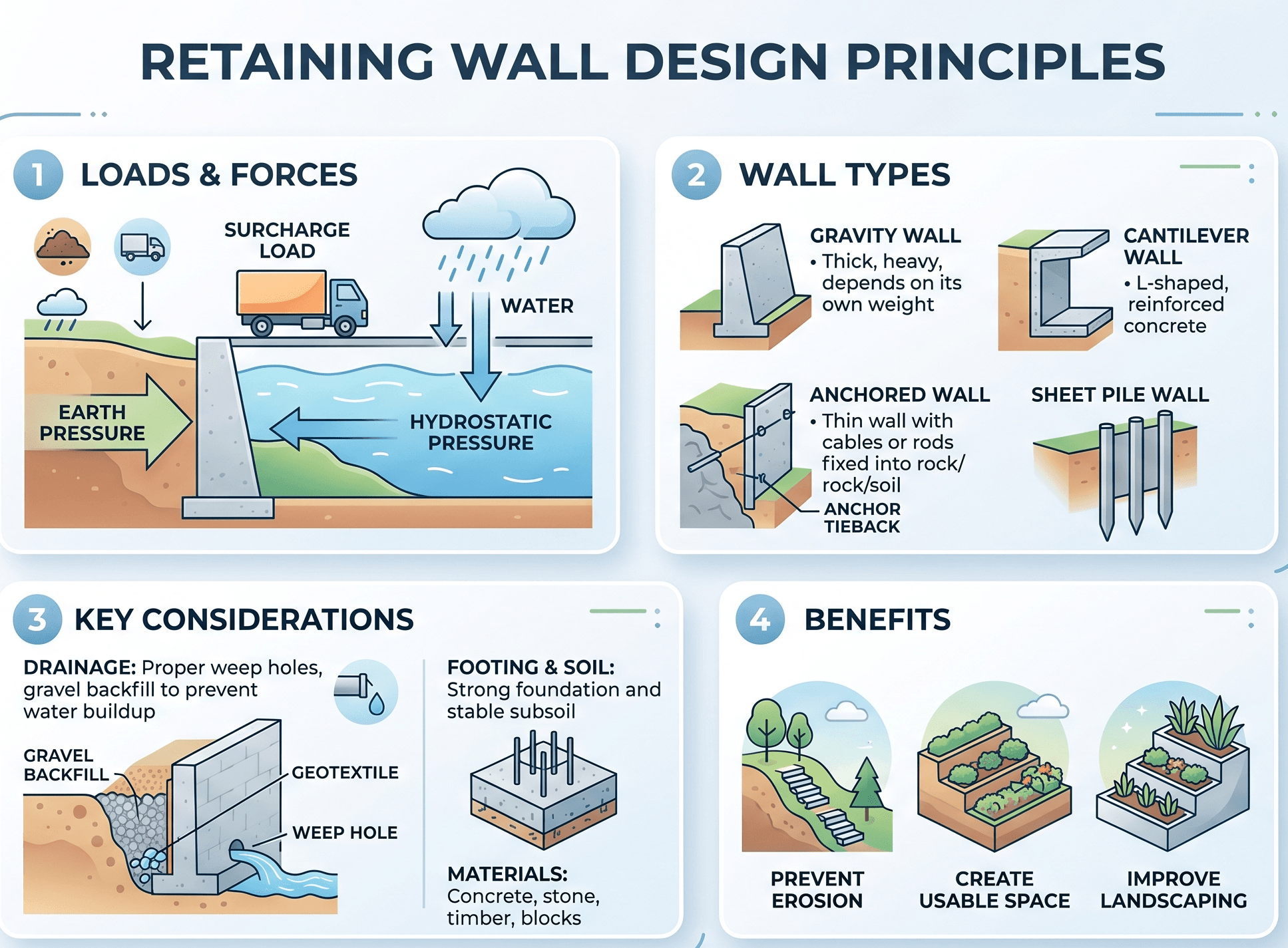
Notice that the wall is only one part of the problem. The retained soil, the water condition, and the foundation soil often control the design just as much as the wall section itself.
What is retaining wall design?
Retaining wall design is the engineering process used to select, proportion, and verify a wall system that can safely hold back soil or rock while keeping movement within acceptable limits. In a practical design, engineers are not only asking whether the wall section is strong enough. They are also asking whether the earth pressures are being modeled reasonably, whether drainage assumptions are credible, whether the foundation can carry the applied stresses, and whether the wall can be built within the physical limits of the site.
This is why retaining wall design sits between geotechnical and structural engineering rather than belonging to only one discipline. The retained soil pushes laterally, water can add substantial demand, the wall must resist sliding and overturning, and the foundation soil must tolerate bearing pressure and settlement. A wall that works in a neat hand calculation may still be the wrong answer if the site has poor drainage control, very soft support soils, or tight movement limits near a building, roadway, or utility.
If you want broader context before going deeper, start with What is Geotechnical Engineering. To compare retaining systems more broadly, review Earth Retaining Structures and Earth Retaining Walls.
Core principles, variables, and units
Most retaining wall problems begin with the same basic physical question: what is trying to move the wall, and what is available to resist that movement? The answer depends on retained height, backfill type, groundwater, surcharge, wall geometry, and the strength of the supporting ground. In conceptual design, engineers usually begin with earth pressure, then move outward into sliding, overturning, bearing, settlement, and serviceability checks.
Key variables and typical ranges
For first-pass work, common starting variables include retained height \(H\), soil unit weight \(\gamma\), effective friction angle \(\phi\), surcharge \(q\), and the relevant earth pressure coefficient. Drained granular backfill often falls somewhere around 17 to 20 kN/m³, or roughly 105 to 125 pcf, with friction angles commonly in the upper 20s to mid-30s in degrees. Those are not default design values. They are only orientation values until the project’s actual geotechnical data and backfill specification are confirmed.
- \(H\) Retained height of soil behind the wall; m or ft; one of the strongest drivers of lateral force and overturning demand.
- \(\gamma\) Soil unit weight; kN/m³ or pcf; should reflect whether the backfill is drained, saturated, or effectively submerged.
- \(\phi\) Effective friction angle; degrees; central to estimating active and passive pressure in granular soils.
- \(q\) Uniform surcharge; kPa or psf; may come from traffic, pavement, storage, embankment loads, or nearby structures.
- \(K_a, K_0, K_p\) Active, at-rest, and passive earth pressure coefficients; dimensionless; selected according to wall movement and design assumptions.
- \(P_a\) Resultant active earth force per unit wall length; kN/m or lb/ft; often idealized as acting at one-third of the retained height for a triangular stress distribution.
One of the fastest ways to make a retaining wall check misleading is to assume high-quality granular backfill before confirming what the project will actually specify, place, compact, and drain.
Decision logic or design workflow
Strong retaining wall design starts with site screening, not with reinforcing steel or wall thickness. Engineers first define retained height, available footprint, groundwater, surcharge, nearby structures, utilities, and allowable deformation. That lets them screen likely wall families before spending time on a concept that does not fit the site.
Define height, footprint, groundwater, loading, and movement tolerance. Shortlist feasible wall systems. Estimate earth and water pressures. Check sliding, overturning, bearing, settlement, structural actions, and overall stability. Revise the concept if drainage, constructability, or performance limits are not satisfied.
This matters because wall type selection is often more important than fine-tuning a poor concept. A cantilever wall may work well where a base slab fits and the supporting soils are competent. A mechanically stabilized earth wall may be economical where reinforcement length is available. A wall system that looks efficient in section can still be unsuitable if the site is too constrained, if groundwater is difficult to control, or if adjacent structures cannot tolerate even small movements.
Equations and calculations
For simple first-pass checks with level drained backfill, engineers commonly estimate active earth pressure using a triangular stress distribution plus a rectangular surcharge component. These equations are useful for orientation and conceptual sizing, but they should never replace project-specific geotechnical judgment.
In these expressions, \(\sigma_h\) is lateral stress at depth \(z\), \(P_a\) is the resultant active earth force, \(\gamma\) is soil unit weight, \(q\) is uniform surcharge, and \(K_a\) is the active earth pressure coefficient. Once the driving force is estimated, engineers compare it with resistance from wall self-weight, soil over the heel where applicable, base friction, reinforcement, and any passive resistance that can actually be justified and preserved in the field.
At that point, the design usually moves into external stability checks such as sliding and overturning, base pressure checks for bearing, and structural design of the wall elements themselves. For walls that are sensitive to movement or are part of a larger earth-support problem, the designer may also need to evaluate deformation, global stability, and construction staging rather than relying only on classical hand methods.
Worked example
Example
Consider a conceptual retaining wall holding back 4.0 m of drained granular soil with \(\gamma = 18\) kN/m³ and \(\phi = 32^\circ\), and assume no surcharge in the first pass. For level backfill using Rankine active pressure, \(K_a \approx (1-\sin 32^\circ)/(1+\sin 32^\circ) \approx 0.31\). The first-pass active force is:
That force acts at approximately one-third of the retained height above the base for the triangular soil-pressure component. Even this simple calculation is already useful because it gives the designer a first estimate of the overturning demand and the required resisting weight or geometry. The next steps are to check whether the chosen wall type has enough resistance to sliding and overturning, whether the toe pressure is acceptable for the supporting ground, and whether the wall will settle or rotate too much for the project.
This example also shows why height is such a dominant design variable. The soil-force term scales with \(H^2\), so even a moderate increase in retained height can change the wall type that makes the most sense economically and technically. A solution that works well at one height can quickly become inefficient, unstable, or too movement-sensitive at a larger retained height.
Engineering judgment and field reality
Retaining walls often underperform for reasons that do not show up clearly in a clean textbook problem. Real backfill can be more variable than assumed. Drainage zones may be simplified during construction. Outlet locations can become clogged. Excavation overbreak can alter base geometry. Foundation soils may be weaker or more compressible than the conceptual model suggested. This is why engineering judgment is not optional in retaining wall design.
Groundwater is one of the biggest field realities. Many wall problems that appear structural are actually water-management problems. If the wall was designed with drained assumptions but the drainage system does not perform as intended, hydrostatic pressure can add substantial load, reduce effective stress, soften foundation soils, and cause movement that the wall section itself was never meant to absorb. Good wall design tries to reduce sensitivity to those kinds of imperfections rather than pretending they will never happen.
Many retaining wall failures are not caused by a wall being too thin. They are caused by poor drainage, mismatched backfill assumptions, or field conditions that no longer match the original design model.
When this breaks down
Simple retaining wall methods stop being reliable when the site differs too much from the idealized assumptions behind the equations. That includes layered backfill, sloping retained ground, irregular surcharge, restricted wall movement, significant seepage, soft foundation soils, seismic loading, and interaction with nearby foundations or utilities. In those cases, a single earth pressure coefficient and a few hand checks may no longer describe the actual controlling behavior.
The method also breaks down when the designer focuses only on local wall checks and ignores system behavior. A wall can appear acceptable in sliding and overturning but still be a poor design because of settlement, excessive movement, poor reinforcement geometry, global instability, erosion risk, or long-term maintenance problems. Once the wall becomes part of a slope, excavation support system, or broader earthwork problem, the analysis usually has to expand.
Common pitfalls and engineering checks
- Using active pressure assumptions when the wall may not move enough to mobilize them.
- Ignoring hydrostatic pressure or assuming the drainage system will always work perfectly.
- Relying on passive resistance that may be lost through future excavation, erosion, or disturbance.
- Checking wall stability without also checking bearing pressure, settlement, and overall stability.
- Using soil parameters that do not match the specified backfill or verified geotechnical condition.
A costly design mistake is treating the wall face as the problem while underestimating the retained soil mass, the drainage path, or the foundation behavior that actually controls performance.
| Parameter | Symbol | Typical units | Notes |
|---|---|---|---|
| Retained height | \(H\) | m, ft | Often the strongest driver of lateral load and overturning. |
| Soil unit weight | \(\gamma\) | kN/m³, pcf | Must reflect the actual moisture and drainage condition assumed in design. |
| Friction angle | \(\phi\) | degrees | Should come from the project backfill or geotechnical data, not generic optimism. |
| Surcharge | \(q\) | kPa, psf | Often overlooked when roads, pavements, storage, or structures exist behind the wall. |
| Pressure coefficient | \(K_a, K_0, K_p\) | dimensionless | Must match how the wall actually moves and what assumptions can be defended. |
Visualizing retaining wall design
A useful way to visualize retaining wall design is to divide the problem into three linked questions: what is pushing the wall, what is resisting that push, and what performance limit matters most at this site. That frame helps keep the design grounded in real project behavior rather than isolated equations.
If the site cannot support the drainage concept, footprint, or movement assumption behind the wall, the concept usually needs to change before detailed design continues.
Relevant standards and design references
Retaining wall design usually draws from both geotechnical and structural references, along with agency requirements tied to the project sector.
- AASHTO LRFD Bridge Design Specifications: Commonly used for transportation retaining walls and walls associated with bridge approaches and roadway systems.
- ACI 318: Relevant when reinforced concrete wall elements, stems, heels, toes, and detailing must be designed structurally.
- FHWA earth retention guidance: Helpful for wall selection, reinforced soil concepts, and practical retaining system design in transportation projects.
- NCMA and segmental retaining wall guidance: Frequently used for modular block systems, drainage details, and reinforced soil wall layout.
- Project geotechnical report and local code criteria: These often govern soil parameters, water assumptions, seismic criteria, and construction limitations more directly than generic references do.
Frequently asked questions
Wall selection is the early step of choosing a wall family that fits the site. Retaining wall design is the broader engineering process of defining loads, drainage, stability, structural demand, and serviceability for that chosen system.
The controlling issue depends on the project, but common drivers are earth pressure, groundwater, sliding resistance, overturning stability, toe bearing, settlement, reinforcement length, and allowable movement near adjacent structures.
Drainage matters because trapped water adds hydrostatic pressure, can reduce effective stress, and often becomes the real reason a retaining wall moves or underperforms in the field.
They become less reliable when the site has layered soils, sloping backfill, irregular surcharge, uncertain drainage, restrained movement, soft foundations, seismic demand, or nearby assets sensitive to deformation.
Summary and next steps
Retaining wall design is a system-level problem involving soil, water, structure, and constructability. Good design requires more than checking whether a wall section is strong enough. It requires matching the wall type, drainage concept, geometry, and assumptions to the real site conditions.
The most reliable designs are usually the ones that respect field reality: groundwater may not behave ideally, backfill quality may vary, and space limits may control the whole concept. When you understand what is pushing the wall, what resists it, and what performance limit matters most, the design process becomes much clearer.
Where to go next
Continue your learning path with these curated next steps.
-
Read a deeper dive on Earth Retaining Structures
Compare common retaining systems and understand when each concept fits better than the others.
-
Study Geosynthetics
Useful for reinforced soil systems, separation layers, filtration details, and drainage design.
-
Practice with the Retaining Wall Calculator
Apply the concept with geometry and loading inputs to see how the wall response changes numerically.