Key Takeaways
- Core idea: Earthquake resistant structures are designed to deform, dissipate energy, and maintain stability instead of behaving like rigid, brittle objects.
- Engineering use: Structural engineers use seismic systems such as shear walls, braced frames, moment frames, diaphragms, dampers, and base isolation to control earthquake response.
- What controls it: Seismic performance depends on hazard level, soil conditions, building geometry, mass, stiffness, ductility, connections, drift limits, and construction quality.
- Practical check: A strong member is not enough; earthquake resistance depends on a complete load path from diaphragm to vertical system to foundation.
Table of Contents
Introduction
Earthquake resistant structures are buildings, bridges, and other systems designed to protect life safety and reduce damage during seismic shaking. They use ductile materials, continuous load paths, lateral-force-resisting systems, strong connections, and sometimes damping or base isolation so earthquake energy can be resisted, redirected, and dissipated without sudden collapse.
How Earthquake Resistant Structures Work
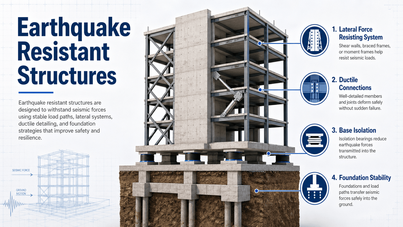
Notice that the structure is not shown as a single “strong” object. The important idea is continuity. Earthquake forces must move through slabs, diaphragms, collectors, frames, walls, connections, and foundations without a weak link causing a brittle failure.
What Are Earthquake Resistant Structures?
Earthquake resistant structures are designed to withstand ground motion by controlling force, deformation, and damage. In structural engineering, the goal is usually not to keep every component perfectly elastic. The goal is to prevent collapse, maintain gravity support, limit dangerous drift, and allow selected parts of the structure to yield in a predictable way.
This is why earthquake resistance is different from ordinary strength. A brittle structure can be very strong under static load and still perform poorly during repeated cyclic shaking. A good seismic system must have strength, stiffness, ductility, redundancy, and a clear load path. The structure must also be detailed so beams, columns, walls, braces, connections, and foundations act together rather than as isolated parts.
Earthquake resistant design is controlled damage prevention. The structure may move and some components may yield, but the system should avoid sudden loss of support, brittle fracture, overturning, or collapse.
How Earthquakes Affect Structures
Earthquakes move the ground rapidly in different directions. A building’s base follows that motion, but the mass of the building tends to resist the change in motion. That inertia creates lateral forces, drift, overturning, torsion, and repeated stress reversals throughout the structure.
Inertia and lateral force
Seismic demand is strongly influenced by building mass. Heavier buildings can generate larger inertial forces because more mass must be accelerated during shaking. This is one reason seismic design often considers the weight of floors, roofs, walls, equipment, cladding, and permanent building contents.
Drift, deformation, and damage
Drift is the sideways movement of one floor relative to another. Some movement is expected, but excessive drift can damage partitions, cladding, stairs, elevators, piping, glazing, and structural members. Earthquake resistant structures control drift without making the building so brittle that it cannot dissipate energy.
Torsion and irregular movement
If the center of mass and center of stiffness are poorly aligned, the building can twist during shaking. Torsion is especially important in irregular plans, setbacks, open first stories, eccentric shear walls, and buildings where stiffness is concentrated on one side.
Core Principles of Earthquake Resistant Design
The best earthquake resistant structures combine several design principles. No single feature makes a building safe by itself. A base isolator, shear wall, brace, or moment frame only works when the surrounding system can deliver forces into it and when the component has enough ductility and anchorage to perform during cyclic loading.
- Continuous load path: Seismic forces must travel from the floor or roof diaphragm into collectors, chords, walls, braces, frames, foundations, and supporting soil.
- Ductility: Structural members and connections should deform without sudden brittle failure.
- Controlled stiffness: The building needs enough stiffness to limit drift, but not so much brittle stiffness that damage concentrates in a weak location.
- Redundancy: Multiple lines of resistance reduce dependence on one wall, frame, brace, or connection.
- Regularity: Simple, symmetric layouts usually perform better than highly irregular layouts with sudden stiffness or strength changes.
- Energy dissipation: Yielding, damping, friction, and isolation can reduce transmitted force and absorb seismic energy.
- Foundation compatibility: The lateral system must be anchored into foundations that can resist overturning, sliding, uplift, and soil-related movement.
For a deeper foundation on how loads move through buildings, see structural loads, structural analysis, and load path analysis.
Common Earthquake Resistant Structural Systems
Earthquake resistant structures use lateral-force-resisting systems to collect, resist, and transfer seismic demand. The best system depends on the building height, occupancy, architecture, seismic hazard, soil conditions, cost, constructability, and required performance level.
| System | How it helps | Best suited for | Design caution |
|---|---|---|---|
| Shear walls | Provide high lateral stiffness and strength through vertical wall elements. | Concrete, masonry, wood, and hybrid buildings where walls can be placed continuously. | Openings, discontinuities, boundary elements, and foundation anchorage must be carefully detailed. |
| Braced frames | Use diagonal members to resist lateral forces through axial tension and compression. | Steel buildings, industrial structures, retrofits, and efficient lateral systems. | Brace buckling, gusset plate detailing, load reversal, and connection ductility are critical. |
| Moment-resisting frames | Use rigid beam-column connections to resist lateral forces through bending. | Buildings that need open floor plans or fewer walls and braces. | Frames may have larger drift demands and require careful connection detailing. |
| Diaphragms and collectors | Collect seismic forces from floors and roofs and deliver them to vertical lateral systems. | Nearly all building types. | Weak diaphragm connections can interrupt the load path even if walls or frames are strong. |
| Base isolation | Lengthens the structural period and reduces acceleration transmitted into the building. | Hospitals, emergency facilities, bridges, museums, and high-value structures. | Utilities, moat gaps, displacement capacity, maintenance, and cost must be addressed. |
| Dampers | Dissipate energy through fluid, friction, yielding, or viscoelastic behavior. | High-rises, retrofits, bridges, and buildings needing drift or acceleration control. | Device placement, inspection access, long-term reliability, and design assumptions matter. |
Many high-performance buildings use a dual approach. For example, a building may combine shear walls with moment frames, or use a primary braced system with supplemental dampers. The goal is not to add complexity for its own sake, but to create a predictable, redundant, and buildable seismic load path.
What Controls Earthquake Resistance?
Seismic performance is controlled by more than the visible structural material. Two buildings with similar steel or concrete frames can behave very differently if one has poor layout regularity, weak diaphragm anchorage, brittle connections, or unfavorable soil conditions.
| Factor | Why it matters | Engineering implication |
|---|---|---|
| Seismic hazard | Ground motion intensity varies by location, fault distance, soil, and probability level. | Higher hazard increases lateral demand, detailing requirements, drift checks, and performance expectations. |
| Site class and soil | Soft soils can amplify shaking, while liquefiable soils can lose strength during an earthquake. | Foundation design, ground improvement, base shear, period effects, and settlement risk may change significantly. |
| Building mass | More mass generally creates larger inertial forces during ground acceleration. | Heavy cladding, equipment, storage, and roof systems must be considered in seismic demand. |
| Stiffness distribution | Sudden stiffness changes can concentrate drift and damage in one story or one side of the building. | Soft stories, weak stories, setbacks, transfer levels, and eccentric cores require special review. |
| Ductility and detailing | Ductile elements can deform and dissipate energy without sudden fracture. | Reinforcement detailing, confinement, weld quality, bolt behavior, and connection geometry are essential. |
| Nonstructural components | Ceilings, piping, façades, equipment, and partitions can create hazards even if the frame remains standing. | Anchorage, bracing, drift compatibility, and clearances are part of earthquake-resistant performance. |
Base Shear and the Simplified Design Idea
Seismic design can become highly analytical, especially for irregular or important structures, but the simplified idea starts with base shear. Base shear is the approximate total horizontal seismic force at the base of the structure. It is not the whole design, but it helps explain why mass, site hazard, and structural response matter.
In this simplified expression, \(V\) is seismic base shear, \(C_s\) is the seismic response coefficient, and \(W\) is effective seismic weight. The coefficient reflects seismic hazard, soil effects, structural period, ductility, importance, and code-defined limits. Engineers then distribute seismic forces through the height of the building and check members, connections, diaphragms, drift, overturning, and foundations.
- V Base shear, usually expressed as a horizontal force such as pounds, kips, newtons, or kilonewtons.
- Cs Seismic response coefficient that captures hazard, soil, structural system behavior, period, and design criteria.
- W Effective seismic weight, including relevant dead load and portions of other loads required by the governing design criteria.
Base shear estimates force demand, but earthquake resistance is judged by system behavior. Drift, ductility, load path, connection detailing, diaphragm action, torsion, and foundation anchorage can control the design even when base shear is not unusually large.
Earthquake Resistance Design Review Checklist
A practical seismic review starts by tracing how shaking demand enters the structure, where it is collected, where it is resisted, and how it reaches the foundation. This checklist is useful for students, designers, and reviewers because it focuses on system behavior rather than isolated member strength.
Start with the seismic hazard and site class. Identify the building mass and expected force path. Check the diaphragm, collectors, chords, vertical lateral system, connections, foundation anchorage, drift compatibility, torsion, irregularities, and nonstructural bracing. Then ask whether the actual construction can deliver the behavior assumed in analysis.
| Check or decision | What to look for | Why it matters |
|---|---|---|
| Load path continuity | Diaphragms, collectors, chords, walls, frames, braces, anchor bolts, and foundations are connected without gaps. | A missing connection can make a strong seismic system ineffective during shaking. |
| Vertical irregularity | Open first stories, transfer levels, setbacks, interrupted walls, or sudden changes in stiffness. | Irregularities can concentrate drift and damage in one story or structural zone. |
| Ductile detailing | Confinement steel, development length, weld quality, bolt detailing, brace connections, and boundary elements. | Ductility depends on details that allow deformation without brittle fracture or crushing. |
| Diaphragm behavior | Roof and floor systems can collect and distribute lateral forces to the intended walls, frames, or braces. | Diaphragm weakness can cause force redistribution, excessive deformation, or local failure. |
| Drift compatibility | Partitions, cladding, stairs, elevators, piping, and glazing can tolerate expected movement. | Nonstructural damage can create hazards and make a building unusable even without collapse. |
| Foundation and soil response | Anchorage, overturning, sliding, uplift, bearing, settlement, liquefaction, and lateral spreading are considered. | Seismic resistance cannot exceed what the foundation and supporting ground can reliably transfer. |
Common Earthquake Failure Modes
Earthquake damage often reveals weak links in the system. The visible crack, buckle, or collapse may be the final symptom, but the root cause is usually a combination of layout, detailing, construction quality, soil response, and incomplete load path assumptions.
Soft-story failure
A soft story occurs when one level, often the ground floor, is much less stiff than the levels above. Parking garages, storefronts, tall lobby spaces, and open first floors can create a concentration of drift and damage in that story.
Short-column failure
Short columns can attract high shear forces because partial-height walls, infill, or architectural elements restrict deformation. This can lead to brittle diagonal cracking or sudden loss of column capacity.
Unreinforced masonry failure
Unreinforced masonry can perform poorly in earthquakes because it lacks ductile reinforcement, reliable wall-to-diaphragm anchorage, and tensile capacity. Parapets, chimneys, walls, and façades can become serious falling hazards.
Pounding and separation problems
Adjacent buildings can collide during shaking when there is not enough separation. Pounding can damage columns, floor edges, façades, and structural corners, especially when floor levels do not align.
To understand failure as a broader structural concept, see structural failure.
New Buildings vs. Seismic Retrofit
New earthquake resistant structures can be designed from the start with a coordinated lateral system, regular layout, ductile detailing, and foundation anchorage. Existing buildings are harder because engineers must evaluate what is already there, identify vulnerable load paths, and add resistance without creating new irregularities.
New construction
In new construction, seismic decisions affect architecture, structural layout, material selection, connection detailing, mechanical clearances, cladding joints, and foundation design. Early coordination is valuable because moving a shear wall, brace bay, or core after the layout is fixed can create expensive compromises.
Existing building retrofit
Retrofit work may include adding shear walls, steel braced frames, collectors, diaphragm strengthening, foundation anchorage, wall ties, column jackets, fiber-reinforced polymer, base isolation, or dampers. The retrofit strategy depends on the existing material system, target performance level, occupancy, disruption tolerance, and construction access.
A retrofit should not only add strength. It should improve the intended load path, avoid creating a new stiffness imbalance, and verify that foundations and connections can accept the added seismic demand.
Engineering Judgment and Field Reality
Earthquake resistant design is only as reliable as the assumptions, details, and construction quality behind it. A computer model may show acceptable forces and drift, but the real building must have correctly placed reinforcement, complete welds, proper anchor installation, compatible nonstructural clearances, and field conditions that match the design intent.
Experienced engineers pay close attention to discontinuities, diaphragm penetrations, embed plates, collector connections, wall boundary zones, brace gusset geometry, construction sequencing, and foundation load transfer. These details are easy to overlook in a simplified diagram, but they often control real seismic performance.
The most dangerous seismic problem is often not the member everyone notices. It is the hidden connection, weak diaphragm edge, missing anchor, poorly confined column zone, or discontinuous wall that prevents the intended seismic system from engaging.
When This Breaks Down
Simplified explanations of earthquake resistance can break down when the structure, ground motion, or site conditions do not behave like the ideal model. The more irregular, important, tall, flexible, or soil-sensitive the structure is, the more careful the engineering review must become.
- Irregular geometry: Setbacks, transfer levels, eccentric cores, and open first stories can create torsion or concentrated drift.
- Weak or flexible diaphragms: A strong wall or frame cannot perform as intended if forces cannot reach it.
- Liquefaction or lateral spreading: Soil movement can damage foundations even if the superstructure is well detailed.
- Brittle material behavior: Unreinforced masonry, poorly confined concrete, and weak connections can fail suddenly.
- Nonstructural hazards: Ceilings, equipment, cladding, piping, and parapets can fail even when the main frame remains stable.
Common Mistakes and Practical Checks
The most common misunderstanding is treating earthquake resistance as a material choice. Steel, concrete, wood, masonry, and composite systems can all perform well or poorly depending on layout, detailing, connections, foundations, and construction quality.
- Assuming “stronger” always means safer: Strength without ductility can still produce brittle failure.
- Ignoring load path: A shear wall or brace is not useful if diaphragms, collectors, and anchors cannot deliver force into it.
- Overlooking torsion: Eccentric stiffness can make one side of a building move more than expected.
- Forgetting nonstructural components: Equipment, ceilings, façades, and piping can create major safety and functionality problems.
- Using idealized models without field checks: Real construction tolerances, penetrations, deterioration, and undocumented modifications can change seismic behavior.
Do not judge earthquake resistance by one visible feature. A building with shear walls, braces, or dampers can still be vulnerable if the diaphragm, connections, foundation, or soil response is not compatible with the intended system.
Relevant Standards, Manuals, and Design References
Earthquake resistant structures are usually designed using a combination of building codes, load standards, material standards, existing-building evaluation procedures, and project-specific performance goals. The references below provide important context for seismic design practice.
- International Building Code: Establishes model building code requirements and references more detailed structural standards used for seismic design.
- ASCE/SEI 7: Provides minimum design loads and load combinations, including seismic criteria for buildings and other structures.
- ASCE/SEI 41: Used for seismic evaluation and retrofit of existing buildings, especially when performance objectives must be defined for an existing structure.
- FEMA and NEHRP seismic guidance: Provides educational design concepts, seismic hazard context, and practical background for understanding earthquake-resistant design.
- Material standards such as ACI, AISC, NDS, and TMS: Provide design and detailing requirements for concrete, steel, wood, and masonry systems that may be part of a seismic load path.
Frequently Asked Questions
An earthquake resistant structure is a building, bridge, or other structure designed to maintain a stable load path and avoid sudden collapse during seismic shaking. It uses lateral systems, ductile detailing, strong connections, and controlled deformation so earthquake energy can be resisted and dissipated.
No building is truly earthquake proof. Earthquake resistant design usually means the structure is intended to protect life safety, limit collapse risk, and control damage for a defined level of shaking. Some critical facilities may be designed for higher performance, but zero damage is not a realistic assumption.
The most important features are a continuous load path, ductile materials and connections, adequate lateral stiffness and strength, regular building layout, reliable diaphragms, good foundation anchorage, and control of drift and torsion. Soil conditions and construction quality can be just as important as the structural system.
Common earthquake resistant systems include shear walls, braced frames, moment-resisting frames, diaphragms, collectors, base isolation, viscous or hysteretic dampers, and dual systems that combine walls or braces with frames. The best choice depends on building height, layout, seismic hazard, occupancy, cost, and performance goals.
Summary and Next Steps
Earthquake resistant structures are designed to reduce collapse risk and control damage during seismic shaking. They do this through a combination of ductile materials, complete load paths, lateral-force-resisting systems, strong connections, drift control, foundation anchorage, and energy dissipation.
The practical workflow is to identify seismic demand, understand the site and structure, trace the load path, select an appropriate lateral system, check drift and torsion, detail for ductility, and verify that field construction can deliver the intended behavior.
Where to go next
Continue your learning path with related Turn2Engineering resources.
-
Structural Loads
Learn how seismic, wind, gravity, snow, and other loads are defined before structural analysis begins.
-
Structural Dynamics
Study vibration, natural period, damping, resonance, and dynamic response concepts that shape seismic behavior.
-
Foundation Design
See how structural reactions, overturning, uplift, and lateral loads are transferred into soil or rock.