
Direct Answer
Short circuit analysis calculates the current that can flow when a low-impedance fault occurs at a specific point in a power system. Engineers use the results to verify interrupting ratings, switchgear withstand, bus bracing, fuse duty, protective-relay sensitivity, and other equipment or safety decisions.
The available current is not a fixed property of the building or system. It changes with fault location, source strength, transformer impedance, conductor impedance, motor and generator contribution, grounding, X/R ratio, and the operating configuration. A complete study therefore evaluates multiple buses and both maximum- and minimum-fault conditions.
How Short-Circuit Current Flows Through a Power System
Fault current flows from every source that can contribute to the fault, through the impedances between those sources and the fault location. The current is highest where the source is strong and total impedance is low.

Utility systems, generators, motors, and some inverter-based resources can contribute current.
Source, transformer, line, cable, busway, reactor, and grounding impedances limit current.
The available current is calculated at each bus or equipment location that requires a duty or protection check.
Available fault current usually decreases as the fault moves farther downstream because additional conductor and equipment impedance is added between the source and the fault.
How Short-Circuit Current Is Calculated
The simplest way to understand a short-circuit calculation is as a Thevenin-equivalent problem: pre-fault driving voltage divided by the equivalent impedance seen from the fault.
General Thevenin Relationship
Balanced Three-Phase Fault
- \(I_{sc}\)Calculated short-circuit current.
- \(V_{th}\)Thevenin equivalent pre-fault voltage.
- \(V_{LL}\)Line-to-line voltage at the faulted bus.
- \(Z_{th}, Z_{eq}\)Equivalent source-to-fault impedance.
Transformer-Only Screening Estimate
At a transformer secondary, a quick screening estimate starts with transformer full-load current and percent impedance:
This transformer-only estimate assumes the upstream source is effectively strong and ignores feeder impedance, motor/generator contribution, X/R, grounding, and switching configuration. Use it for concept checks—not as proof of downstream equipment adequacy.
Inputs That Most Affect Short-Circuit Current
Short-circuit results are dominated by source strength and the impedance between each contributing source and the fault. Small data errors can materially change equipment-duty conclusions.
| Input | Why it matters | Common consequence of bad data |
|---|---|---|
| Utility source data | Defines upstream available fault current and X/R ratio | Every downstream duty result may be too high or too low |
| Transformer impedance | Often the dominant current-limiting element in facility studies | Secondary fault current can be materially miscalculated |
| Cable / feeder impedance | Adds source-to-fault resistance and reactance | Remote fault current may be overstated if actual length is omitted |
| Motor contribution | Large induction/synchronous motors can feed current into the fault initially | Momentary equipment duty may be understated |
| Generator contribution | On-site generators add another fault source | Emergency/parallel operating cases may be missed |
| Grounding | Controls zero-sequence and ground-fault return paths | Ground-fault current and protection sensitivity may be wrong |
| X/R ratio | Controls the asymmetrical DC offset and peak current | Momentary or interrupting duty can be evaluated on the wrong basis |
| System topology | Ties, parallel transformers, generators, and source status change equivalent impedance | The worst-case duty may occur in a non-normal configuration |
Swipe horizontally to view all table columns.
Symmetrical, Asymmetrical, and Peak Current
Fault current is not only one RMS number. The initial waveform can contain a decaying DC offset whose magnitude depends strongly on the X/R ratio and fault inception angle. Equipment may therefore have separate interrupting, momentary, close-and-latch, peak, and short-time withstand considerations.
For deeper treatment of fault types and symmetrical components, see Fault Analysis.
Maximum vs. Minimum Short-Circuit Current
Maximum fault current is mainly an equipment-duty problem; minimum fault current is mainly a protection-sensitivity problem. A complete study needs both where each can control the design.
| Case | Main purpose | Conditions that can increase/decrease current |
|---|---|---|
| Maximum fault current | Breaker interrupting duty, switchgear withstand, bus bracing, fuse interrupting capacity | Strong source, parallel transformers, closed ties, generators online, large motors, minimum source-to-fault impedance |
| Minimum fault current | Relay/fuse sensitivity, remote-fault clearing, backup protection | Weak source, open ties, long feeders, higher impedance, some generators offline, high-resistance fault paths |
Swipe horizontally to view all table columns.
A system can pass maximum-duty checks and still have a protection problem if a remote or impedance-limited fault is too small to operate the intended relay, fuse, or breaker fast enough.
How Short-Circuit Results Are Used for Equipment Duty
A short-circuit calculation becomes useful only when the current is compared with the actual rating basis of the installed equipment at that location.
| Equipment / study use | What is checked | Why it matters |
|---|---|---|
| Circuit breaker | Interrupting rating at applied voltage and applicable asymmetry basis | Breaker must safely interrupt the fault |
| Switchgear / switchboard | Short-circuit withstand, bus bracing, momentary/short-time duty | Assembly must survive thermal and mechanical fault stress |
| Panel / MCC / equipment SCCR | Available fault current at the installed location versus marked rating | Downstream equipment must not be applied above its short-circuit rating |
| Fuse | Interrupting capacity and coordination with other devices | Fuse must interrupt safely and selectively |
| Protective relay | Pickup sensitivity, instantaneous reach, time coordination, ground elements | Protection must detect both strong and weak faults in its intended zone |
| Arc-flash study | Available current plus protective-device clearing behavior | Fault current influences incident-energy calculations but is not the only input |
Swipe horizontally to view all table columns.
Do not compare one source-side fault-current number to every device in the system. Each equipment location should be checked against the available current calculated at that specific point.
IEEE 3002.3-2018 provides recommended practice for conducting short-circuit studies and analyzing device duty in industrial and commercial power systems: IEEE 3002.3-2018.
Practical Short-Circuit Study Workflow
A reliable study is mostly a data and model-quality exercise. The calculation method matters, but bad source data or wrong transformer impedance can invalidate the answer before the solver starts.
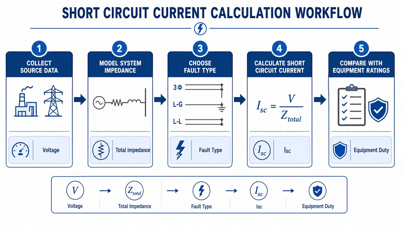
- Verify the one-line and operating configurations.
Confirm sources, transformers, ties, generators, motors, breakers, feeders, and normal/emergency switching states.
- Collect source and equipment data.
Obtain utility fault data, X/R, transformer impedance, conductor length/size, generator and motor data, and equipment ratings.
- Build the network impedance model.
Represent each source-to-fault path with the correct resistance, reactance, grounding, and sequence data needed for the selected method.
- Run the required fault cases.
Evaluate the buses and fault types that matter for maximum duty and minimum protection sensitivity.
- Compare with installed equipment.
Check breaker interrupting rating, switchgear withstand, panel SCCR, fuse duty, relay pickup, and other applicable ratings.
- Carry results into coordination and safety studies.
Use the credible fault-current range when reviewing protective-relay coordination and arc-flash clearing behavior.
For protection-system follow-through, see Protective Relays and Overcurrent Protection.
Worked Example: 1500 kVA Transformer Secondary Fault Current
Estimate transformer-limited three-phase short-circuit current
Assume a 1500 kVA, 480 V, three-phase transformer with 5.75% impedance. Use a transformer-only screening calculation.
Calculate transformer full-load current
Divide by per-unit impedance
Interpret the result
- A downstream feeder adds impedance, so fault current at a remote panel will usually be lower.
- Motors or local generators can add initial contribution and increase certain duties.
- Actual transformer impedance should come from nameplate or project data, not a generic assumption.
- X/R and the applicable equipment rating basis still need to be checked.
Short-Circuit Model QA and Common Mistakes
The most common study errors are model errors, not equation errors. Review the physical system before trusting a precise-looking software result.
| Review item | What to verify | Risk if missed |
|---|---|---|
| Utility data | Maximum/minimum fault current, X/R, date, service configuration | All downstream duties may be based on stale source strength |
| Transformer data | Nameplate kVA, voltage, connection, %Z, parallel operation | Major error in downstream available current |
| Feeder length and size | Actual conductor material, size, length, cable/busway data | Remote current overstated or understated |
| Motor/generator state | Which rotating sources are online in each scenario | Momentary contribution omitted |
| Tie / parallel condition | Normal, emergency, maintenance, and generator-backed states | Worst-case duty may not be studied |
| Grounding | Transformer winding connections, grounded neutral, resistor/reactor values | Ground-fault current wrong |
| Equipment rating | Actual installed breaker, switchgear, panel, MCC, fuse, busway ratings | Study conclusion does not match field equipment |
Swipe horizontally to view all table columns.
Do not use one transformer-secondary estimate as the available fault current for the entire facility. Fault current must be calculated at the specific equipment location and for the operating configuration being evaluated.
Short-Circuit Analysis Engineering References
Short-circuit study methods and equipment-duty criteria depend on system type, voltage class, applicable standards, owner requirements, and the equipment being evaluated.
- IEEE 3002.3-2018 — Recommended Practice for Conducting Short-Circuit Studies and Analysis of Industrial and Commercial Power Systems Short-circuit current calculations, device-duty analysis, model validation, source/equipment data, and study methodology.
- IEC 60909-0 — Short-Circuit Currents in Three-Phase AC Systems Widely used international framework for calculating short-circuit currents in three-phase AC systems.
Frequently Asked Questions
What is short circuit analysis used for?
Short circuit analysis calculates available fault current at specific points in a power system so engineers can verify breaker interrupting ratings, switchgear withstand, equipment SCCR, fuse duty, relay sensitivity, and related protection or safety requirements.
What is the basic short-circuit current formula?
At a basic level, fault current equals the pre-fault driving voltage divided by the equivalent impedance seen from the fault. For a balanced three-phase system, a common form is \(I_{3\phi}=V_{LL}/(\sqrt{3}Z_{eq})\).
Why does transformer impedance matter so much?
Transformer impedance limits the amount of current that can pass from the source to the secondary system. Lower percent impedance generally means higher downstream fault current; higher percent impedance generally means lower current.
What is the difference between maximum and minimum fault current?
Maximum fault current is mainly used for equipment-duty checks. Minimum fault current is mainly used to confirm protective devices can still detect and clear weaker or remote faults.
Is short circuit analysis the same as fault analysis?
They overlap. Short circuit analysis usually focuses on available current and equipment duty, while fault analysis more broadly covers fault types, sequence networks, grounding effects, and protection behavior.
Is short circuit analysis the same as arc flash analysis?
No. Short circuit analysis calculates fault current and equipment duty. Arc flash analysis uses fault current together with clearing time, working distance, equipment configuration, and other factors to estimate incident energy.
Summary and Next Step
Short circuit analysis determines how much fault current can reach a specific point in a power system and how that current compares with the ratings of the equipment that must carry, withstand, detect, or interrupt it.
Strong studies use current source data, actual transformer and conductor impedance, credible operating configurations, maximum and minimum cases, X/R information, and location-specific equipment ratings. The goal is not simply to calculate kA—it is to prove that the installed system is adequately rated and that protection can clear credible faults.