
Direct Answer
Fault analysis is the study of abnormal current paths in an electrical power system. Engineers use it to determine the type and magnitude of a fault, understand how current returns through the network, check breaker and switchgear duty, and verify that protective devices can detect and isolate the fault correctly.
The four core shunt-fault types are single line-to-ground, line-to-line, double line-to-ground, and three-phase faults. Balanced three-phase faults can usually be analyzed with the positive-sequence network alone, while unbalanced faults are commonly solved with positive-, negative-, and zero-sequence networks.
Main Types of Power System Faults
Fault analysis starts by identifying which conductors are connected by the abnormal path. The fault type determines which sequence networks are required and how grounding influences the result.
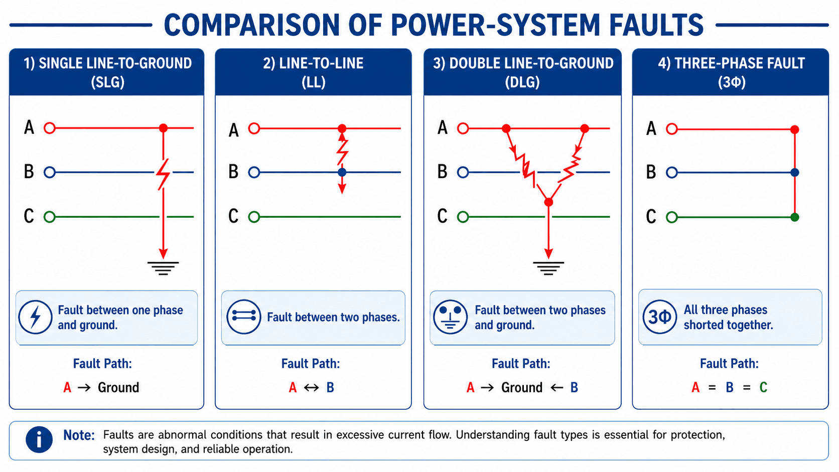
| Fault type | Abbreviation | Balanced? | Ground path involved? | Key engineering concern |
|---|---|---|---|---|
| Single line-to-ground | SLG or L-G | No | Yes | Grounding and zero-sequence impedance strongly control the current |
| Line-to-line | LL or L-L | No | No | Positive- and negative-sequence networks determine the result |
| Double line-to-ground | DLG or L-L-G | No | Yes | All three sequence networks are involved |
| Three-phase | 3Φ or L-L-L | Yes | Not required for the balanced three-phase calculation | Often produces severe equipment duty and is simple to calculate |
Swipe horizontally to view all table columns.
A three-phase fault is often used for maximum-duty screening, but it is not automatically the highest-current fault at every location. Grounded systems with low zero-sequence impedance can produce line-to-ground fault current that approaches or exceeds the three-phase value.
Fault Current Calculation and the Inputs That Control It
At its simplest, fault current is determined by the driving voltage divided by the equivalent impedance seen from the fault location. Real studies build that equivalent from the source, transformers, conductors, rotating machines, grounding system, and network configuration.
Thevenin Fault-Current Relationship
- If Fault current at the study location.
- Vth Thevenin equivalent pre-fault voltage at the faulted bus.
- Zth Thevenin equivalent impedance from all contributing sources to the fault.
Simplified Three-Phase Bolted Fault
For a balanced three-phase fault, the positive-sequence impedance \(Z_1\) is the primary sequence network used in the calculation. Real short-circuit software may use subtransient machine reactances, transformer impedance, cable/line impedance, and standards-specific treatment of voltage factors and equipment duty.
| Input | Why it matters | Typical error if modeled poorly |
|---|---|---|
| Utility / source strength | Sets the upstream Thevenin impedance and available current | Incorrect breaker-duty or relay-sensitivity result |
| Transformer impedance | Often dominates downstream fault-current limitation | Large error in low-voltage available fault current |
| Cable / line impedance | Reduces fault current as distance from the source increases | Remote faults may appear easier to detect than they really are |
| Grounding configuration | Defines the zero-sequence current return path | Ground-fault current can be drastically wrong |
| Generator / motor contribution | Rotating machines can feed current into a fault during the initial period | Equipment duty can be understated |
| X/R ratio | Controls DC offset and asymmetrical peak behavior | Momentary or interrupting duty may be evaluated incorrectly |
| Operating configuration | Ties, generators, and parallel sources change equivalent impedance | One study case may not represent the worst or minimum condition |
Swipe horizontally to view all table columns.
Maximum fault current is usually critical for equipment duty. Minimum fault current is critical for protection sensitivity and remote-fault clearing. A complete study should consider both where they affect the design.
Why Symmetrical Components Are Used in Fault Analysis
Symmetrical components convert an unbalanced three-phase condition into three balanced sequence systems: positive, negative, and zero sequence. That transformation makes unbalanced-fault calculations much easier to organize and solve.
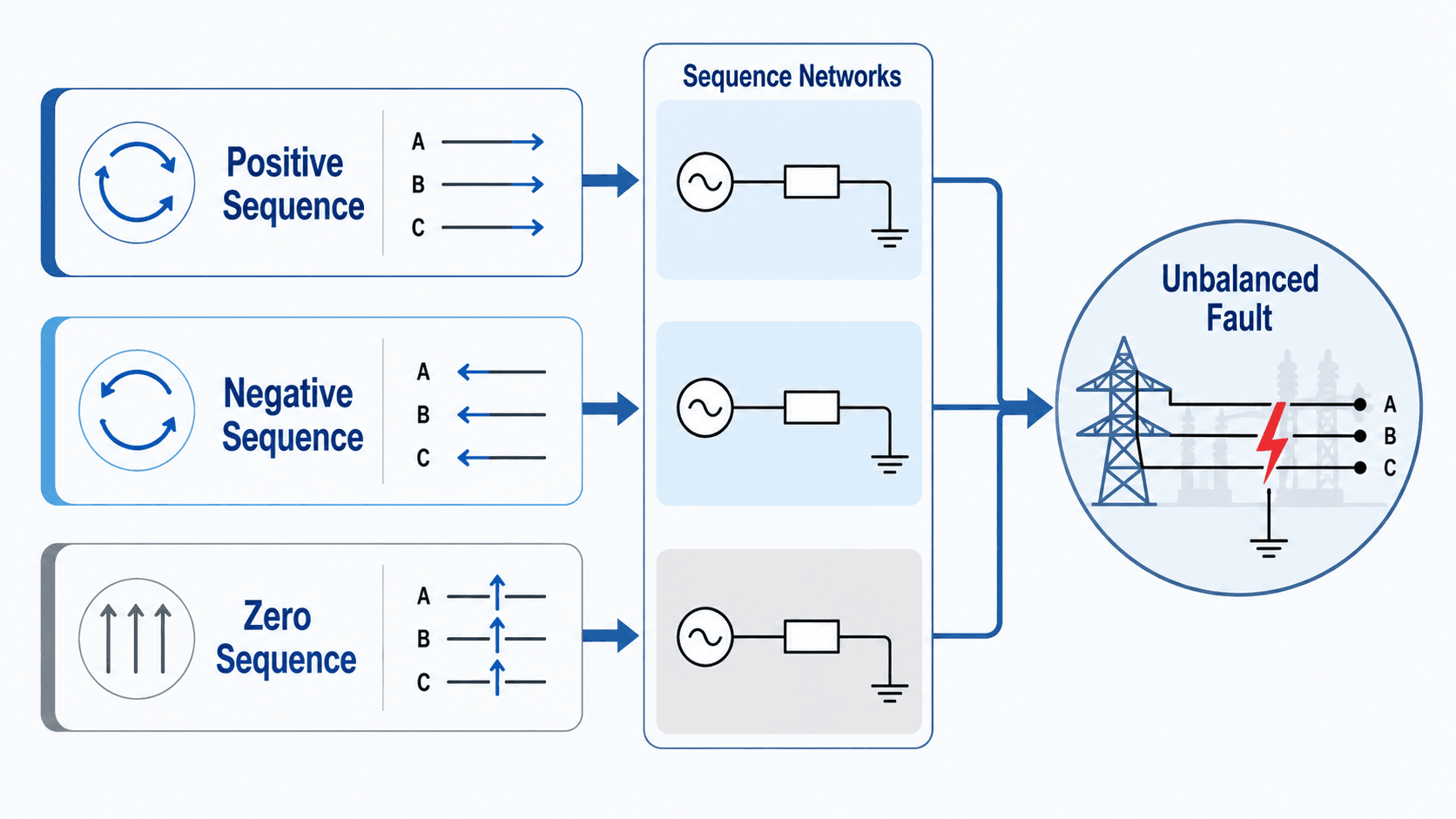
Positive Sequence
Three equal phasors separated by 120° with the normal phase rotation. Positive sequence represents the normal balanced operating system and is present in every fault calculation.
Negative Sequence
Three equal phasors separated by 120° with reverse phase rotation. Negative sequence appears during unbalanced faults and can be damaging to rotating machines because it produces reverse-rotating magnetic fields.
Zero Sequence
Three phasors equal in magnitude and angle. Zero-sequence current requires a physical return path through ground, neutrals, transformer winding connections, or grounding equipment.
From Sequence Currents Back to Phase Currents
Once the sequence currents are known, the phase quantities can be reconstructed. For phase A:
The full transformation uses the 120° rotation operator \(a\), but the important practical idea is that an unbalanced phase condition can be represented as the sum of three balanced sequence systems.
How Sequence Networks Connect for Each Fault Type
The same power system has positive-, negative-, and zero-sequence networks, but those networks connect differently depending on the fault. That connection is what changes the resulting fault current.
| Fault type | Sequence networks involved | Core relationship | What most affects the result |
|---|---|---|---|
| Three-phase | Positive sequence only | Balanced fault | Positive-sequence source and network impedance |
| Single line-to-ground | Positive + negative + zero | Sequence networks in series for the ideal bolted case | Grounding and zero-sequence impedance |
| Line-to-line | Positive + negative | Zero-sequence current is absent | Positive- and negative-sequence impedance |
| Double line-to-ground | Positive + negative + zero | Parallel/series sequence-network combination | Both phase impedance and ground-return impedance |
Swipe horizontally to view all table columns.
Single Line-to-Ground Fault Current
For a bolted single line-to-ground fault at a bus with pre-fault phase voltage \(V\), the sequence-network form is:
This equation makes the grounding dependence obvious: if the zero-sequence path changes, the ground-fault current changes. Transformer winding connections and grounded neutrals can therefore have a major impact even when the positive-sequence one-line looks unchanged.
How Fault Analysis Is Used for Equipment-Duty Checks
Fault-study results are compared with equipment interrupting, momentary, close-and-latch, short-time, and withstand ratings so the system can safely survive and clear a credible fault.
| Study result | Typical engineering use | What it verifies |
|---|---|---|
| Symmetrical RMS fault current | Breaker interrupting and short-circuit rating review | Protective device can interrupt the available current under its rating basis |
| Asymmetrical / peak current | Momentary and mechanical-duty review | Bus, switchgear, breakers, and equipment can withstand initial electromagnetic forces |
| X/R ratio | DC-offset and interrupting-duty evaluation | Equipment rating assumptions match the actual asymmetry of the fault current |
| Minimum fault current | Protection sensitivity | Relays, breakers, or fuses still operate for remote or impedance-limited faults |
| Ground-fault current | Ground-fault equipment and relay review | Zero-sequence path, grounding system, and pickup sensitivity are adequate |
Swipe horizontally to view all table columns.
A calculated current value is not the final engineering answer. The result must be compared with the correct equipment rating basis, applied voltage, X/R conditions, protective device characteristics, and the standard or manufacturer rating applicable to that equipment.
IEEE 3002.3-2018 specifically addresses short-circuit studies for industrial and commercial power systems, including fault-current calculation, device-duty evaluation, model validation, data requirements, and analysis methods: IEEE 3002.3-2018.
How Fault Analysis Supports Protection Coordination
Protection coordination uses fault-study results to decide which relay, breaker, recloser, or fuse should operate first and how quickly it should clear the fault.
-
Determine fault magnitude at each protection zone.
Calculate maximum and minimum currents for relevant fault types and operating conditions.
-
Verify protective-device sensitivity.
Confirm the intended device can detect the lowest credible fault in its zone without responding to normal load, inrush, or acceptable transient conditions.
-
Coordinate operating time.
Use relay curves, fuse curves, breaker clearing time, and communication-assisted schemes so the nearest appropriate device clears first.
-
Check backup protection.
Upstream protection must clear the fault if the primary relay, breaker, fuse, communication channel, or trip circuit fails.
For deeper treatment, see Protective Relays, Overcurrent Protection, and Transmission Line Protection.
NERC PRC-027-1 requires coordination of protection systems installed to detect and isolate faults on Bulk Electric System elements so those protection systems operate in the intended sequence during faults: NERC PRC-027-1.
Practical Fault Analysis Workflow
A strong fault study is primarily a modeling and data-quality exercise. Correct equations cannot rescue an incorrect one-line diagram, wrong transformer impedance, or missing source contribution.
-
Verify the one-line diagram.
Confirm sources, transformers, buses, feeders, breakers, motors, generators, grounded neutrals, normally open ties, and actual operating configuration.
-
Collect source and equipment data.
Obtain utility fault data, machine reactance, transformer percent impedance, cable/line impedance, grounding impedance, and protective-device ratings.
-
Build positive-, negative-, and zero-sequence models.
Verify transformer winding connections and grounding paths so unbalanced-fault cases are represented correctly.
-
Calculate faults at the buses that matter.
Evaluate service equipment, switchgear, MCCs, major panels, transformer terminals, remote feeder ends, and other protection zones.
-
Compare results with equipment ratings.
Check interrupting duty, withstand, bus bracing, switchgear ratings, CT performance, and other applicable equipment limits.
-
Use the results in the protection study.
Verify pickup, sensitivity, coordination, backup protection, ground-fault performance, and clearing sequence.
Before trusting a software result, ask whether the model represents the actual system condition being evaluated. Source strength, tie status, standby generators, motor contribution, transformer taps, and grounding can all change the answer.
Worked Example: Three-Phase Fault on a 480 V Bus
Calculate symmetrical fault current and interpret equipment duty
Assume a balanced 480 V three-phase bus with an equivalent positive-sequence impedance of \(0.020\ \Omega\) from the source to the fault location. Ignore fault resistance and additional machine contribution for this simplified example.
Calculate three-phase fault current
Use the line-to-line form of the balanced three-phase bolted-fault equation.
Compare with breaker interrupting rating
Use the calculated current as one input to the equipment-duty review.
13.9 kA available fault current exceeds a 10 kA interrupting rating.
13.9 kA is below 22 kA, but the full rating basis and application still must be verified.
Lower source-to-fault impedance produces higher available fault current.
Ground faults, sequence networks, DC offset, motor contribution, or protective-device operating time.
Use the calculated fault currents in equipment-duty and protection-coordination studies.
Fault Analysis Engineering References
These references support the page’s short-circuit study, device-duty, and protection-coordination context. Final project work requires the applicable equipment standards, utility data, owner criteria, protection philosophy, and project-specific modeling assumptions.
- IEEE 3002.3-2018 — Recommended Practice for Conducting Short-Circuit Studies and Analysis of Industrial and Commercial Power Systems Short-circuit calculations, fault-current analysis, device-duty evaluation, modeling assumptions, data requirements, and model validation.
- NERC PRC-027-1 — Coordination of Protection Systems for Performance During Faults Protection-system coordination so faults are detected and isolated in the intended sequence on Bulk Electric System elements.
- NERC — Protection and Control Standards Current protection and control standards covering coordination, relay loadability, misoperations, maintenance, and fault performance.
Frequently Asked Questions
What is fault analysis in power systems?
Fault analysis is the study of abnormal electrical current paths so engineers can calculate fault current, classify the fault type, evaluate equipment duty, and verify that protective devices detect and isolate the fault correctly.
What are the four main power system fault types?
The four common shunt-fault types are single line-to-ground, line-to-line, double line-to-ground, and three-phase faults.
What is the difference between fault analysis and short-circuit analysis?
They overlap heavily. Short-circuit analysis usually emphasizes available fault current and equipment duty, while fault analysis often includes the broader interpretation of fault type, sequence networks, grounding, current paths, and protection response.
Why are symmetrical components used?
Symmetrical components convert an unbalanced three-phase condition into positive-, negative-, and zero-sequence systems. This makes single line-to-ground, line-to-line, and double line-to-ground faults much easier to analyze.
Is a three-phase fault always the highest-current fault?
No. Three-phase faults often produce severe current and are commonly used for equipment-duty screening, but a line-to-ground fault can equal or exceed the three-phase current in some grounded systems depending on positive-, negative-, and zero-sequence impedance.
Why is minimum fault current important?
Minimum fault current is important because protective devices still need to detect and clear remote, impedance-limited, or weak-source faults. A system can have acceptable maximum-duty ratings and still have inadequate protection sensitivity.
Summary and Next Step
Fault analysis explains what happens when the normal current path in a power system is replaced by an abnormal phase-to-phase or phase-to-ground path. The fault type determines the current path, sequence-network connection, and the influence of grounding.
Strong fault studies combine accurate source data, transformer and conductor impedance, grounding, machine contribution, X/R ratio, system configuration, and sequence-network modeling. The results then support equipment-duty checks and protection coordination rather than existing as isolated current values.