
Table of Contents
Introduction
A heat pump system is an HVAC system that transfers heat between a building and outdoor air, the ground, or water. A reversible refrigerant circuit allows many heat pumps to provide both heating and cooling by changing which heat exchanger absorbs heat and which one releases it.
Unlike a furnace, a heat pump does not rely only on combustion or electric resistance to produce usable heat. It uses compressor work to move existing thermal energy. The best heat pump is therefore not determined by equipment efficiency alone; climate, building load, distribution, low-temperature capacity, site conditions, controls, and installation quality all matter.
Key Takeaways
- Core idea: A heat pump moves heat through evaporation, compression, condensation, and expansion.
- Major options: Common configurations include ducted air-source, ductless, ground-source, water-source, air-to-water, packaged, and dual-fuel systems.
- What controls performance: Source temperature, required delivery temperature, compressor operation, heat exchangers, airflow or water flow, defrost, controls, and distribution losses all matter.
- Practical check: Select equipment from a building load calculation and manufacturer performance data at the actual project design conditions—not from floor area alone.
Heat Pump System Types at a Glance
The quickest way to understand heat pumps is to separate two decisions: where the system exchanges heat and how it distributes that heat inside the building.
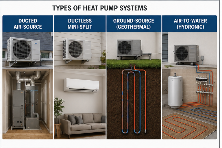
A ductless mini-split is usually an air-source heat pump. An air-to-water unit is also commonly air-source, but it transfers heat into water instead of directly heating indoor air. Ground-source systems exchange heat with a buried loop or another ground-coupled source.
Which Heat Pump Type Fits Which Situation?
Start with the existing building infrastructure. Usable ductwork often points toward a ducted system, while buildings without ducts may be better suited to ductless or hydronic distribution. Ground-source systems can reduce exposure to outdoor-air temperature swings but require suitable site conditions and a more involved installation.
A building with usable ductwork
A ducted air-source heat pump is often the most direct option. Before reusing the ducts, verify leakage, insulation, airflow, return-air paths, filter pressure drop, and total external static pressure. Existing ductwork should not automatically be assumed adequate.
A building without ductwork
Ductless mini-splits can serve individual rooms or zones without constructing a central duct system. Air-to-water heat pumps may fit buildings with compatible radiant floors, fan coils, or low-temperature radiators.
A project seeking a stable heat source
A ground-source system exchanges heat with ground or groundwater conditions that are generally more stable than outdoor air. The potential performance benefit must be weighed against loop-field design, excavation or drilling, pumping energy, site access, and first cost.
A building retaining a furnace
A dual-fuel system can use the heat pump during favorable conditions and the furnace when controls call for the alternate heat source. The changeover strategy should consider equipment capacity, outdoor temperature, utility rates, comfort, and owner priorities.
Choose the system family from the building, climate, distribution, and site constraints first. Compare specific equipment models only after those requirements are defined.
How a Heat Pump System Works
Most comfort heat pumps use a reversible vapor-compression cycle. Refrigerant circulates through heat exchangers, a compressor, one or more metering devices, and a reversing valve. Its pressure, temperature, and phase change as it travels around the circuit.

Heating mode
In heating mode, low-pressure refrigerant enters the outdoor heat exchanger and absorbs energy from outdoor air, ground-loop fluid, or water. The refrigerant evaporates and returns to the compressor as vapor.
The compressor raises the refrigerant pressure and temperature. The hot, high-pressure refrigerant then enters the indoor heat exchanger, where it releases useful heat to indoor air or a water loop and condenses. A metering device reduces the refrigerant pressure before it returns to the outdoor heat exchanger.
Cooling mode
In cooling mode, the indoor coil functions as the evaporator. It absorbs sensible heat from indoor air and can remove latent heat as water vapor condenses on the cold coil. The compressor raises refrigerant pressure, and the outdoor coil rejects the collected indoor heat plus compressor energy to the outdoors.
What the reversing valve changes
The reversing valve directs compressor discharge and suction flow to the appropriate heat exchangers. It changes the refrigerant path; it does not make the compressor rotate backward.
Why the coil names change
“Evaporator” and “condenser” describe what happens to the refrigerant, not a permanent equipment location. The evaporator absorbs heat as refrigerant evaporates. The condenser rejects heat as refrigerant condenses. In a reversible heat pump, the indoor and outdoor coils exchange these functions.
Red and blue lines indicate relatively warmer and cooler portions of the circuit. They should not be interpreted as universal indicators of liquid and vapor because refrigerant phase depends on circuit location and operating condition.
Heat Pump System Components
A heat pump is more than an outdoor unit. The refrigeration circuit, indoor distribution, controls, drainage, electrical supply, and supplemental heat must work as one system.
Compressor
The compressor draws in low-pressure refrigerant vapor and discharges higher-pressure, higher-temperature vapor. Compressor type and speed control affect capacity modulation, cycling, sound, part-load operation, and low-temperature performance.
Indoor and outdoor heat exchangers
The indoor and outdoor coils are application-specific heat exchangers. Their capacity depends on airflow or water flow, surface condition, refrigerant distribution, pressure drop, approach temperature, and available heat-transfer area.
Reversing valve
A four-way reversing valve routes compressor discharge and suction flow so the system can change operating modes. Some heat pumps are heating-only or cooling-only and do not use the same reversible arrangement.
Expansion and flow-control devices
An expansion device meters refrigerant and produces the pressure reduction needed before the evaporator. Reversible systems may use electronic expansion valves, thermostatic expansion valves, fixed orifices, check valves, or paired metering arrangements depending on the equipment design.
Air handler or indoor terminals
A ducted system usually includes an indoor coil, blower, filter, drain pan, and cabinet connected to supply and return ducts. Ductless systems use wall-mounted, ceiling-mounted, floor-mounted, or concealed terminal units. Hydronic systems use water-to-air or water-based terminal equipment.
Fans, pumps, ducts, and piping
Fans move air across heat exchangers and through occupied spaces. Ground-source and hydronic systems add pumps, piping, valves, strainers, air separators, expansion tanks, and terminal equipment. These auxiliary components consume energy and influence whole-system performance.
Condensate and defrost drainage
Indoor cooling coils remove moisture and require a correctly trapped and routed condensate drain. Air-source outdoor units can release substantial water during winter defrost. Drainage must not create ice hazards, damage the building, or allow water to refreeze against the coil.
Controls and sensors
Thermostats and equipment controllers coordinate compressor speed, fan or pump operation, reversing-valve position, defrost, supplemental heat, lockouts, alarms, and protection limits. Variable-capacity equipment may require matched communicating controls to provide its intended functions.
Detailed Heat Pump System Types
Ducted air-source heat pump
A ducted split system normally has an outdoor unit, indoor coil or air handler, refrigerant piping, controls, and a supply-and-return duct system. It is often practical for buildings that already have correctly sized and serviceable ductwork.
The design must account for duct leakage, insulation, airflow, return-air paths, external static pressure, filter resistance, and room-by-room distribution. A highly rated outdoor unit cannot overcome a restrictive or poorly balanced duct system.
Ductless mini-split and multi-split heat pump
A ductless heat pump connects one or more indoor terminal units to an outdoor unit without a central duct system. It can provide effective zoning for additions, renovations, older buildings, and spaces with different occupancy schedules.
Indoor-unit placement affects air mixing, temperature sensing, sound, condensate routing, appearance, and service access. In multi-split systems, connected indoor-unit capacity and simultaneous zone demand must be checked against outdoor-unit performance.
Packaged heat pump
A packaged heat pump contains the major refrigeration and air-handling assemblies in one cabinet. Packaged units may be installed on roofs, at grade, or through an exterior wall depending on the application.
The designer must review weather exposure, structural support, roof curbs, duct penetrations, sound, condensate, service access, outside-air requirements, and the effect of exterior ductwork.
Ground-source or geothermal heat pump
A ground-source heat pump exchanges heat with a buried closed loop, groundwater system, or another ground-coupled source. Ground temperatures are generally more stable than outdoor-air temperatures, which can reduce the required temperature lift during severe weather.
Ground-loop configuration, soil or rock conditions, drilling or excavation, pumping energy, antifreeze concentration, groundwater rules, thermal balance, permitting, and long-term accessibility must be evaluated.
Water-source heat pump
Water-source heat pumps are common in multifamily and commercial buildings with a shared water loop. Individual units exchange heat with the loop, while boilers, cooling towers, fluid coolers, or ground loops maintain an acceptable loop-temperature range.
This arrangement can allow different zones to heat and cool at the same time, but central pumping, loop-temperature control, ventilation, condensate, acoustics, and unit access require coordinated design.
Air-to-water heat pump
An air-to-water heat pump transfers energy between outdoor air and a water loop. The water may serve radiant floors, fan coils, compatible radiators, buffer tanks, or domestic-water heating equipment where the complete system is designed for that purpose.
Required supply-water temperature is a critical design variable. As the required delivery temperature rises, compressor lift generally increases and available capacity and COP may decline. Low-temperature emitters can therefore improve system compatibility.
Dual-fuel heat pump
A dual-fuel system pairs a heat pump with a furnace or another heating source. Controls can stage or switch the equipment based on outdoor temperature, available heat-pump capacity, utility rates, comfort requirements, or an engineered balance point.
Efficiency, Capacity, and Cold-Weather Performance
Heat-pump performance cannot be represented by one number under every condition. Seasonal cooling ratings, seasonal heating ratings, and performance at a specific outdoor temperature answer different questions.
Coefficient of performance
- \(COP_{heating}\) Heating coefficient of performance; dimensionless.
- \(\dot{Q}_{heating}\) Useful heating rate delivered to the building, measured in consistent power units such as kW or Btu/h.
- \(\dot{W}_{electric}\) Electrical power input within the defined system boundary, expressed in the same power units.
A heating COP greater than one is possible because the machine moves environmental heat in addition to converting electrical input into compressor work. Comparisons must use the same system boundary. A compressor-only value is not equivalent to a whole-system value that includes fans, pumps, controls, crankcase heat, and supplemental resistance heat.
SEER2
Seasonal Energy Efficiency Ratio 2 represents total seasonal cooling output divided by the associated electrical energy consumption under the applicable rating procedure. It helps compare cooling performance but does not predict one building’s exact annual consumption.
HSPF2
Heating Seasonal Performance Factor 2 represents seasonal space-heating output divided by seasonal electrical energy consumption under the applicable rating procedure. It is useful for equipment comparison, but it does not replace design-temperature capacity data.
EER2
Energy Efficiency Ratio 2 compares cooling capacity and electrical input at a specified rating condition. It represents a defined operating point rather than an entire cooling season.
Capacity and efficiency are different
Capacity indicates how much heating or cooling the unit can deliver. Efficiency indicates how much input is required to provide that output. A heat pump can remain operational at a low outdoor temperature while delivering less capacity than the building requires.
Why outdoor temperature affects an air-source heat pump
During heating, an air-source heat pump must absorb energy from increasingly cold outdoor air while delivering heat at a useful indoor temperature. As outdoor temperature falls, the required temperature lift generally increases. Capacity and COP may decline, although the amount depends on the equipment design and control strategy.
Cold-climate heat pumps
Cold-climate equipment is designed and tested for useful low-ambient operation. Selection still requires manufacturer capacity and power data at the project winter design condition. A cold-climate designation or high seasonal rating does not prove that one unit can carry every building’s peak heating load without supplemental heat.
Defrost cycle
During cold, humid heating operation, the outdoor coil can operate below the frost point. Accumulated frost restricts airflow and reduces heat transfer. The controls periodically initiate defrost, commonly by temporarily reversing the cycle so hot refrigerant warms the outdoor coil.
Defrost is a normal function. Excessive, incomplete, or unusually frequent defrost can indicate airflow, sensor, control, refrigerant, drainage, or equipment-selection problems.
Auxiliary and backup heat
Supplemental heat may operate during defrost, rapid recovery, equipment staging, or weather conditions where the building load exceeds available heat-pump capacity. The backup source may be electric resistance heat, a furnace, a boiler, or another heating system.
Heat Pump System Selection Matrix
Use this matrix to identify system families worth evaluating. Final selection still requires load calculations, design-condition performance data, distribution review, utility information, code compliance, and installation feasibility.
| System type | Indoor distribution | Common best fit | Primary design considerations |
|---|---|---|---|
| Ducted air-source split | Central supply and return ducts | Buildings with usable ductwork and central distribution | Duct leakage, static pressure, airflow, low-temperature capacity, backup heat, and electrical service |
| Ductless mini-split or multi-split | Individual wall, ceiling, floor, or concealed terminals | Additions, renovations, zoned spaces, and buildings without central ducts | Terminal placement, condensate, connected capacity, simultaneous loads, sound, and service access |
| Packaged air-source heat pump | Ductwork connected to one packaged cabinet | Rooftop, through-wall, manufactured-home, and compact packaged applications | Weather exposure, structural support, duct routing, penetrations, sound, drainage, and maintenance access |
| Air-to-water heat pump | Radiant floors, fan coils, or compatible hydronic emitters | Hydronic buildings that can operate at suitable water temperatures | Required supply temperature, buffer volume, freeze protection, pumping, controls, and emitter capacity |
| Ground-source heat pump | Ducted air or hydronic distribution | Projects with suitable geology, land or drilling access, and long-term ownership | Loop design, site conditions, pumping energy, first cost, antifreeze, permitting, and thermal balance |
| Water-source heat pump | Local ductwork or room-level air distribution | Commercial and multifamily buildings with a shared water loop | Loop-temperature control, pumping, ventilation, condensate, acoustics, and central heat rejection or addition |
| Dual-fuel heat pump | Usually central ductwork | Buildings retaining or adding a furnace for alternate heating | Balance point, fuel rates, venting, control sequence, lockouts, equipment matching, and maintaining two heat sources |
No row is universally best. A ductless system may be well suited to a small zoned retrofit but awkward for many enclosed rooms. A ground-source system may reduce outdoor-temperature sensitivity but require substantial site work. An air-to-water system may work well with low-temperature radiant heating but be a poor match for emitters that require very high supply-water temperatures.
How to Choose a Heat Pump System
Selection should proceed from building requirements to equipment—not from a preferred product backward to the load. Use the workflow below to keep the major decisions in the correct order.

- Establish design conditions: Identify winter and summer outdoor design conditions, indoor setpoints, humidity targets, ventilation loads, occupancy, and process requirements.
- Calculate heating and cooling loads: Account for envelope heat transfer, infiltration, ventilation, solar gain, internal loads, and room-by-room requirements.
- Review existing infrastructure: Determine whether ducts are correctly sized and sealed, ductless terminals can serve the zones, or hydronic emitters can operate at compatible temperatures.
- Evaluate source and site options: Review outdoor-unit location, airflow, sound, snow, drainage, structural support, ground-loop feasibility, groundwater restrictions, and service access.
- Check performance at design conditions: Compare delivered capacity, power input, COP, compressor operating range, defrost behavior, and fan or pump energy at the actual project conditions.
- Define supplemental heat: Determine whether backup heat is needed for peak load, defrost, resilience, recovery, or operating-cost optimization.
- Verify electrical requirements: Review compressor, fan, pump, heater, disconnect, conductor, overcurrent, panel, and service requirements using applicable equipment data and electrical rules.
- Plan controls and commissioning: Confirm thermostat compatibility, sensors, staging, setbacks, defrost, alarms, airflow, refrigerant setup, water flow, balancing, and documentation.
Example: older house without usable ductwork
Consider an older house with no usable ducts, several occupied zones, and limited space for major interior construction. Ductless single-zone or multi-zone heat pumps may initially fit better than a central ducted system.
The final choice still depends on room loads, door positions, indoor-unit placement, outdoor-unit capacity, condensate routing, winter performance, sound, available wall space, and electrical capacity. A single indoor unit in a hallway should not automatically be expected to condition every closed bedroom.
Example: new building with radiant floors
For a new building with low-temperature radiant floors and space for a mechanical room, an air-to-water or ground-source water-to-water system may deserve closer evaluation. The required supply-water temperature at winter design conditions would be one of the first technical checks.
If the radiant system can meet the building load with relatively low water temperature, the heat pump may operate more favorably than it would with emitters that require much hotter water.
Do not size a heat pump by matching the nameplate capacity of the existing furnace or air conditioner. Existing equipment may be oversized, and rated heat-pump capacity may differ substantially from delivered capacity at the project design condition.
Installation and Design Considerations
A heat pump is part of a larger building system. Real performance depends on how the equipment, envelope, air or water distribution, controls, and occupants interact.
Load and capacity matching
Oversized equipment can short-cycle, provide poor humidity control, create temperature swings, and spend less time in efficient modulation ranges. Undersized equipment may rely heavily on supplemental heat or fail to maintain setpoint during design weather.
Variable-capacity equipment expands the operating range but does not eliminate the need for correct load calculations and design-condition selection.
Single-stage, two-stage, and variable-capacity systems
- Single-stage: Operates at one primary compressor capacity and may cycle more frequently at light load.
- Two-stage: Provides a lower and higher operating stage, improving load matching compared with a single-stage unit.
- Variable-capacity: Adjusts compressor output over a wider range, which can improve comfort, reduce cycling, and support low-temperature capacity when correctly selected and controlled.
Ductwork and airflow
Verify total external static pressure, filter pressure drop, coil pressure drop, supply and return sizing, leakage, insulation, and register performance. Low airflow can reduce capacity, increase temperature differences, contribute to coil icing, and activate equipment protection.
For deeper guidance, review HVAC static pressure, air handling units, and air changes per hour in HVAC.
Outdoor-unit location
Provide manufacturer-required airflow and service clearances. Avoid locations where roof runoff, drifting snow, vegetation, recirculated discharge air, vehicle impact, corrosive discharge, or persistent ice can impair operation.
Heating-mode condensate and defrost water need a safe drainage path. Elevating the unit may be appropriate where snow accumulation or ice formation would otherwise block the coil.
Indoor-unit location
Air handlers require filter access, coil access, condensate protection, service space, and correctly connected supply and return ducts. Ductless terminals need unobstructed airflow, suitable mounting, service access, and reliable condensate drainage.
Refrigerant piping
Line length, diameter, elevation difference, oil return, insulation, joint quality, contamination control, pressure testing, evacuation, and charge adjustment affect reliability. Refrigerant work should be completed by qualified personnel using the equipment instructions and applicable safety requirements.
Hydronic integration
Air-to-water and water-source designs require confirmed flow rates, pressure drop, pump selection, air removal, expansion control, freeze protection, buffer strategy, minimum system volume, water quality, and compatible terminal temperatures.
Thermostats and control settings
Large thermostat setbacks can trigger rapid recovery and supplemental heat, depending on the control strategy. Balance points, compressor lockouts, supplemental-heat lockouts, staging delays, and defrost support should be deliberately configured rather than left to assumptions.
Commissioning checklist
- Confirm installed model numbers and matched indoor and outdoor equipment.
- Verify airflow or water flow at the intended operating stages.
- Confirm filter, coil, duct, piping, and terminal pressure losses.
- Check refrigerant setup using the manufacturer’s approved procedure.
- Test heating, cooling, defrost, supplemental heat, safeties, and mode transitions.
- Verify condensate and defrost-water drainage.
- Confirm thermostat settings, lockouts, staging, schedules, and sensors.
- Check vibration, sound, equipment support, and service clearances.
- Record baseline temperatures, pressures, power, airflow or flow rate, and control status where appropriate.
- Provide operating and maintenance instructions to the owner.
Common Problems and Troubleshooting Clues
Many complaints that appear to be compressor problems originate in airflow, distribution, sensors, controls, maintenance, or equipment selection. The observations below are screening clues, not a substitute for qualified diagnosis.
- Long runtimes: Can be normal for variable-capacity equipment. Investigate when the building cannot maintain setpoint, auxiliary heat is excessive, airflow is weak, or energy use changes unexpectedly.
- Frequent auxiliary heat: Review outdoor temperature, thermostat setup, recovery settings, staging, heat-pump capacity, defrost frequency, sensors, and whether the backup heat is being unnecessarily energized.
- Outdoor coil frost: Light frost can occur before normal defrost. Heavy ice, fan contact, blocked drainage, or ice that does not clear requires investigation.
- Short cycling: Possible causes include oversizing, minimum-load mismatch, control problems, restricted airflow, sensor location, pressure protection, or refrigeration faults.
- Uneven room temperatures: Review room loads, duct balancing, return paths, terminal placement, closed doors, zoning logic, insulation, infiltration, and solar exposure.
- Weak airflow: Check the filter, coil condition, blower settings, duct restrictions, closed dampers, blocked grilles, and external static pressure.
- Water leakage: Inspect drain pans, traps, drains, pumps, insulation, equipment level, and freeze-related damage. Shut down equipment when leakage threatens electrical components or the building.
- Failure to change modes: Thermostat configuration, controls, reversing-valve operation, wiring, sensors, or refrigeration faults may be involved.
- Unusual noise: Check for loose panels, vibration isolation, fan contact, ice, refrigerant-line contact, bearing problems, and transmitted structural noise.
- Unexpectedly high energy use: Review weather, setpoints, resistance heat, dirty filters or coils, airflow, duct leakage, refrigerant operation, envelope changes, and operating schedules.
Routine owner maintenance
- Inspect or replace filters at an interval appropriate for the building and filter loading.
- Keep outdoor coils clear of leaves, lint, snow blockage, and vegetation.
- Keep supply and return grilles open and unobstructed.
- Inspect accessible condensate drains for blockage or leakage.
- Watch for persistent ice, unusual sounds, water leakage, or unexplained energy changes.
- Follow the manufacturer’s cleaning and maintenance instructions.
Professional maintenance
A qualified service provider can inspect electrical connections, controls, refrigerant operation, coil condition, airflow or water flow, condensate systems, defrost, supplemental heat, sensors, safeties, and performance trends.
Ground-loop and hydronic systems may also require fluid-condition, pressure, pump, strainer, air-removal, water-quality, and freeze-protection checks.
Do not open a refrigerant circuit, bypass electrical protection, force a reversing valve, or troubleshoot energized equipment unless you are trained and authorized to perform that work.
A high-efficiency heat pump connected to poor ductwork, incorrect controls, restricted filters, or incompatible hydronic emitters can perform worse than a lower-rated system that is correctly selected, installed, and commissioned.
Heat Pump Comparisons and Common Misconceptions
Heat pump vs. air conditioner
An air conditioner and an air-source heat pump can use similar vapor-compression equipment for cooling. The heat pump includes the components and controls needed to reverse the refrigerant circuit and provide heating.
Heat pump vs. furnace
A heat pump primarily transfers heat, while a furnace releases heat through combustion or electric resistance. Heat-pump capacity and COP vary with operating conditions. Furnace selection requires separate consideration of fuel, venting, combustion air, efficiency, and distribution.
Heat pump vs. boiler
A boiler heats water or produces steam for hydronic distribution. An air-to-water or water-to-water heat pump can serve compatible hydronic loads, but available water temperature and capacity may differ. Existing high-temperature emitters must be evaluated rather than assumed compatible.
Heat pump vs. chiller
A chiller is selected primarily to produce chilled water or another chilled fluid. A reversible chiller or water-to-water heat pump may provide both heating and cooling, depending on its configuration. Read more about the components and heat-rejection equipment used in a chiller system.
“Heat pumps do not work below freezing”
Outdoor air still contains thermal energy below 32°F or 0°C. Many heat pumps continue operating below freezing, but available capacity, COP, defrost, supplemental heat, and operating limits depend on the specific equipment and conditions.
“Auxiliary heat means the system is broken”
Auxiliary heat can be part of the intended design. It may operate during defrost, rapid recovery, extreme weather, or when the building load exceeds available heat-pump capacity. Unexpected auxiliary operation during mild weather should be investigated.
“A mini-split uses a different basic cycle”
Mini-split describes the equipment arrangement and distribution method. Most ductless heat pumps still use the same basic vapor-compression principles as ducted air-source systems.
“A larger heat pump is always better”
Oversizing can increase cycling, reduce humidity control, create temperature swings, and move operation outside favorable modulation ranges. Correct sizing balances heating, cooling, backup strategy, distribution, and design-condition performance.
“A higher rating guarantees lower utility bills”
Ratings support equipment comparison under defined procedures. Actual energy use also depends on weather, setpoints, envelope performance, duct or piping losses, controls, energy prices, maintenance, backup heat, and installation quality.
Heat Pump Engineering References
These official sources support the operating principles, classifications, efficiency terminology, and selection considerations discussed on this page.
- U.S. Department of Energy — Heat Pump Systems Supports the fundamental heat-transfer explanation and descriptions of air-source, ductless, ground-source, and advanced heat-pump configurations.
- ENERGY STAR — Air-Source Heat Pumps Supports air-source heat-pump operation, system benefits, equipment selection, and ducted versus ductless configurations.
- ENERGY STAR — Heat Pump Equipment Key Product Criteria Supports current terminology for SEER2, HSPF2, EER2, COP, split systems, packaged equipment, and cold-climate performance criteria.
Frequently Asked Questions
Yes. Outdoor air still contains usable thermal energy below freezing, and many air-source heat pumps are designed for low-temperature operation. Delivered capacity, COP, defrost requirements, and the need for supplemental heat depend on the specific equipment and outdoor condition.
Backup heat may support the system during extreme weather, defrost, rapid recovery, equipment staging, or conditions where the building load exceeds available heat-pump capacity. Its operation should be intentionally controlled rather than treated as an automatic sign of failure.
A mini-split describes a split-system arrangement with an outdoor unit and one or more indoor terminals. Many mini-splits are reversible air-source heat pumps, although cooling-only mini-split equipment also exists.
In heating mode, the outdoor coil can operate below the frost point, causing moisture from outdoor air to freeze on the coil. The system periodically enters defrost to remove frost before it significantly blocks airflow and reduces heat transfer.
Both can cool a building using a vapor-compression cycle. A reversible heat pump also changes the refrigerant path so the outdoor coil absorbs heat and the indoor coil releases heat during heating operation.
Summary and Next Steps
A heat pump system transfers heat between a building and outdoor air, the ground, or water. Reversible systems use the same basic refrigeration circuit for heating and cooling by changing the refrigerant path and exchanging the roles of the indoor and outdoor heat exchangers.
The best system is not simply the unit with the highest published efficiency rating. Selection must account for design loads, capacity at actual operating conditions, distribution, airflow or water flow, site constraints, supplemental heat, electrical capacity, controls, installation quality, and commissioning.
Where to go next
-
Vapor Compression Cycle
Study the evaporation, compression, condensation, and expansion processes behind most heat pumps.
-
Refrigeration Cycles
Compare heat-pump operation with refrigerators, air conditioners, and chillers.
-
Air Handling Unit
Learn how blowers, coils, filters, dampers, and ducts support a central heat-pump system.