
Table of Contents
Introduction
A chiller system removes heat from water or a water-glycol solution and circulates the cooled fluid to air-handling units, fan coils, or process equipment. The warmed fluid returns to the chiller, where its heat is transferred to refrigerant and ultimately rejected to outdoor air or through condenser water and a cooling tower.
The chiller itself is only one part of the installation. A complete chilled-water system also depends on pumps, piping, valves, cooling coils, heat-rejection equipment, sensors, electrical service, and controls that operate the equipment in the correct sequence.
Key Takeaways
- Core idea: A chiller does not create cold; it transfers heat from a building or process to an outdoor heat sink.
- Three flow paths: Chilled water, refrigerant, and the heat-rejection medium perform different jobs and normally remain physically separated.
- Main comparison: Air-cooled systems reject heat directly to outdoor air, while water-cooled systems use condenser water and a cooling tower.
- Selection priority: Cooling-load profile, climate, water availability, maintenance capability, redundancy, and lifecycle cost matter more than nominal tonnage alone.
- Performance check: Whole-plant efficiency includes pumps, cooling-tower fans, controls, flow, temperature conditions, and staging—not only chiller compressor power.
How a Chiller System Works
A water-cooled plant is easiest to understand by following the heat. Heat enters the chilled water at the building, passes into refrigerant inside the chiller, moves into condenser water, and is released outdoors at the cooling tower.
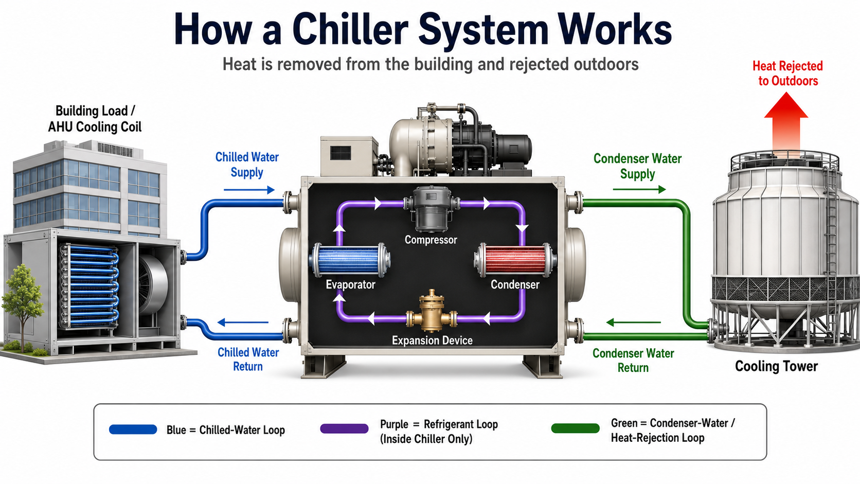
The three circuits transfer heat in sequence without normally mixing. Chilled water does not circulate through the compressor, and condenser water does not travel through the building cooling coils.
What Is Included in a Chiller System?
A chiller is the refrigeration machine that lowers the temperature of a circulating liquid. A chiller system includes the machine and all equipment required to collect heat, transport cooling, reject heat, maintain flow, and control operation.
The Chiller Package
A typical vapor-compression chiller package contains an evaporator, compressor, condenser, expansion device, refrigerant piping, local controls, and protective safeties. Depending on the design, the condenser rejects heat to outdoor air or to a separate condenser-water circuit.
Central Plant Equipment
The plant may include chilled-water pumps, condenser-water pumps, cooling towers, expansion tanks, air separators, strainers, isolation valves, check valves, bypass piping, water-treatment equipment, electrical distribution, and plant-level controls.
Distribution and Terminal Equipment
Insulated piping carries chilled water to cooling coils in an air handling unit, fan-coil unit, process heat exchanger, or other terminal device. The coil transfers heat from air or process fluid into the water before the warmer water returns to the plant.
A chiller normally cools water rather than supplying conditioned air directly. The air-handling system uses that chilled water to cool and dehumidify the air delivered to occupied spaces.
The Three Loops That Move Heat
Each loop has a separate fluid boundary and engineering purpose. Understanding those boundaries makes the complete system easier to operate, troubleshoot, and design.
1. Chilled-Water Loop
The chilled-water loop carries cooling from the plant to the building or process. The chiller lowers the water temperature at the evaporator, and a pump circulates the supply water to cooling coils. The water absorbs heat at the load and returns warmer to the chiller.
- Purpose: Carry heat from the building or process to the evaporator.
- Main equipment: Evaporator, pumps, piping, coils, control valves, expansion tank, air separator, strainers, and sensors.
- Important measurement: The temperature difference between chilled-water return and supply, commonly called chilled-water delta-T.
2. Refrigerant Loop
The refrigerant circuit remains inside the chiller. Refrigerant absorbs heat in the evaporator, the compressor raises its pressure and temperature, the condenser rejects its heat, and the expansion device lowers its pressure before the cycle repeats.
This is the same basic process described by the vapor compression cycle. The evaporator and condenser are both heat exchangers that transfer energy without intentionally mixing the fluids.
3. Heat-Rejection Loop
In a water-cooled plant, condenser water carries heat from the chiller condenser to the cooling tower. The tower transfers that heat to outdoor air, primarily through evaporation, and the cooler water returns to the condenser.
An air-cooled chiller performs the same overall heat-rejection task with condenser coils and fans. Outdoor air passes across the coils, so the plant does not require a separate cooling tower or condenser-water loop.
When system behavior becomes confusing, start at the building load and trace heat through each boundary. The temperature and flow measurements should tell a consistent story from the cooling coil to the outdoor heat sink.
Major Chiller System Components
The components below perform three basic jobs: absorb heat, move fluids, and reject heat. Controls coordinate those jobs as the building load and outdoor conditions change.

Evaporator
The evaporator is the heat exchanger where refrigerant absorbs heat from the chilled water. Water and refrigerant remain separated by the heat-exchanger surface. Fouling, low water flow, trapped air, or abnormal refrigerant conditions can reduce heat transfer and available capacity.
Compressor
The compressor moves refrigerant through the cycle and raises its pressure so that the refrigerant can reject heat at the condenser. Common chiller compressor families include scroll, screw, centrifugal, and reciprocating designs.
Condenser
The condenser transfers heat out of the refrigerant. An air-cooled condenser uses outdoor air and fans. A water-cooled condenser transfers heat to condenser water, which then carries the heat to a cooling tower.
Expansion Device
The expansion device meters refrigerant and reduces its pressure before the refrigerant enters the evaporator. The pressure reduction allows the refrigerant to absorb heat at the required evaporating condition.
Chilled-Water Pump
The chilled-water pump moves water between the evaporator and cooling loads. Pump selection must account for required flow, pipe and equipment pressure losses, control-valve requirements, operating range, redundancy, and part-load control.
Condenser-Water Pump
The condenser-water pump circulates water between a water-cooled condenser and the cooling tower. It is not used in a conventional air-cooled chiller system.
Cooling Tower
The cooling tower rejects condenser heat to outdoor air. Tower performance is affected by outdoor wet-bulb conditions, airflow, water flow, fill condition, spray distribution, fan control, and water quality.
Controls, Valves, and Sensors
Temperature sensors, pressure sensors, flow meters or switches, control valves, variable-frequency drives, local chiller controls, and the building automation system coordinate startup, temperature control, staging, reset strategies, alarms, and shutdown.
For a broader view of air-side and plant-side equipment, see HVAC system components.
Types of Chiller Systems
Chillers can be classified by how they reject heat, how they drive the refrigeration process, and which compressor technology they use. These classifications describe different aspects of the same machine.
Air-Cooled Chillers
Air-cooled chillers use condenser fans to move outdoor air across finned condenser coils. They avoid cooling-tower water use and reduce plant equipment, but their performance is strongly affected by outdoor dry-bulb temperature and condenser-air recirculation.
Water-Cooled Chillers
Water-cooled chillers transfer condenser heat into a water loop connected to a cooling tower. The arrangement adds pumps, piping, controls, tower maintenance, and water treatment, but it can provide favorable operating efficiency for many larger or heavily loaded facilities.
Vapor-Compression Chillers
Vapor-compression chillers use an electrically driven compressor to circulate refrigerant. They are the most familiar type in commercial HVAC and can use scroll, screw, centrifugal, or reciprocating compressors depending on equipment size and design.
Absorption Chillers
Absorption chillers use thermal energy—such as steam, hot water, direct-fired heat, or recoverable waste heat—to drive the refrigeration process. They can reduce electrical compressor demand but require a suitable heat source and should be compared using complete fuel, water, maintenance, and operating costs.
Modular Chiller Plants
Modular systems combine multiple smaller units to create total plant capacity. They can provide staged operation, easier expansion, and incremental redundancy, although the complete system still requires careful hydraulic design, controls, service access, and part-load evaluation.
A chiller may be described by several labels at once. For example, a machine can be a water-cooled, vapor-compression, centrifugal chiller installed in a variable-primary-flow plant.
Air-Cooled vs. Water-Cooled Chiller Systems
The primary difference is the condenser heat sink. The better choice depends on climate, load profile, water availability, mechanical space, noise, maintenance resources, utility costs, reliability, and lifecycle economics.

| Selection factor | Air-cooled system | Water-cooled system |
|---|---|---|
| Heat rejection | Condenser fans reject heat directly to outdoor air. | Condenser water carries heat to a cooling tower. |
| Supporting equipment | No cooling tower or condenser-water pumps. | Requires a cooling tower, condenser-water pumps, piping, controls, and water treatment. |
| Water use | Little or no ongoing condenser-water consumption. | Requires makeup water to replace evaporation, blowdown, and drift losses. |
| Installation | Generally simpler, with fewer plant components and less indoor equipment. | More complex plant layout, installation, controls, and commissioning. |
| Maintenance | Requires coil, fan, refrigerant, control, and water-side maintenance. | Adds tower service, water treatment, basin care, condenser cleaning, and condenser-water equipment. |
| Efficiency tendency | Performance is strongly affected by outdoor dry-bulb temperature. | Often achieves lower chiller kW/ton, but total plant energy must include pumps and tower fans. |
| Space and location | Often installed outdoors and requires adequate airflow and service clearances. | Usually requires indoor plant space plus an outdoor cooling-tower location. |
| Common fit | Projects prioritizing simplicity, lower water use, limited plant space, or lower system complexity. | Larger or heavily loaded facilities where lifecycle savings justify added equipment and maintenance. |
These are broad tendencies, not universal rules. Equipment performance varies with capacity, compressor type, entering and leaving water temperatures, ambient conditions, unloading strategy, controls, and manufacturer design.
Compare annual plant energy, water, maintenance, replacement risk, controls, installed cost, and operating conditions—not only one full-load efficiency value from two equipment schedules.
Common Chilled-Water System Configurations
The piping and pumping arrangement determines how water is distributed, how chillers are protected, and how the plant responds as building load changes.
Constant Primary Flow
A constant-primary-flow system maintains approximately constant flow through an operating chiller. Three-way valves, bypass piping, or another control strategy may be used to maintain required evaporator flow as the cooling load changes.
The arrangement is straightforward, but pumping energy can remain high when distribution flow does not decrease at part load.
Primary-Secondary Flow
Primary pumps establish flow through each operating chiller, while secondary pumps circulate water through the building distribution system. A common pipe or hydraulic decoupler allows primary and secondary flow to differ.
The controls must prevent excessive bypassing, unintended reverse flow, poor temperature separation, and inefficient chiller staging.
Variable Primary Flow
A variable-primary-flow system varies flow through both the chillers and distribution system using variable-speed pumps. The arrangement can reduce pumping energy and equipment count.
Controls must respect each chiller’s allowable flow range, minimum flow, rate-of-flow change limitations, and staging requirements.
Multiple-Chiller Plants
Multiple chillers can provide staged capacity, improved load matching, expansion flexibility, and redundancy. Effective staging considers current load, available capacity, equipment efficiency, minimum run time, auxiliary energy, maintenance status, and reserve requirements.
An efficient design can perform poorly when bypass valves leak, sensors drift, pumps run faster than necessary, or staging logic keeps too many chillers online at low load.
Chiller System Selection Guide
Use this workflow to identify the system families and plant arrangements that deserve detailed analysis. The result is a shortlist, not a final equipment selection.
- Calculate the cooling load: Establish peak load, hourly and seasonal load profiles, minimum load, ventilation load, humidity-control needs, process requirements, and future expansion.
- Define operating priorities: Rank first cost, annual energy, water use, reliability, redundancy, noise, heat recovery, low-temperature operation, and maintenance simplicity.
- Screen heat-rejection options: Compare air-cooled and water-cooled systems using local dry-bulb and wet-bulb conditions, water cost, water availability, plume concerns, outdoor space, and mechanical-room constraints.
- Choose capacity increments: Compare one large chiller, multiple chillers, and modular equipment based on minimum load, staging, redundancy, maintainability, and expansion plans.
- Evaluate equipment technologies: Compare manufacturer performance at the project’s expected loads and water temperatures rather than relying on generic compressor assumptions.
- Select the distribution arrangement: Evaluate constant-primary, primary-secondary, and variable-primary flow based on plant size, control capability, allowable chiller flow, and pumping energy.
- Model whole-plant operation: Include chillers, chilled-water pumps, condenser-water pumps, cooling-tower fans, auxiliaries, water use, and control sequences across the annual load profile.
- Review lifecycle risk: Consider maintenance staffing, water treatment, refrigerant strategy, equipment access, replacement pathways, controls, lead times, and consequences of failure.
Example Selection Reasoning
Consider a facility with substantial year-round cooling, many part-load hours, available plant space, access to water, and trained operating staff. A water-cooled multi-chiller plant may justify detailed lifecycle evaluation because it can stage capacity and use favorable condenser-water conditions.
A smaller facility with intermittent cooling, limited water availability, constrained maintenance resources, and a preference for simpler installation may benefit from an air-cooled system. Neither example creates a universal tonnage boundary.
Request performance data at the project’s design and expected part-load conditions. A selection based only on nominal tonnage and one rating point can misrepresent annual energy use and minimum-load behavior.
Useful Design Tools
- HVAC load calculation guide — reviews the inputs and methods used to estimate heating and cooling loads.
- HVAC load calculator — provides a preliminary load and tonnage estimate for early planning.
- Pump head calculator — supports preliminary total dynamic head and pressure-loss evaluation.
Calculator results are preliminary and do not replace equipment selections, pipe-network analysis, manufacturer data, or project-specific engineering.
Chiller Capacity and Efficiency
Chiller capacity represents the rate at which heat is removed from the chilled-water circuit. In U.S. HVAC practice, capacity is commonly expressed in refrigeration tons, where one refrigeration ton equals 12,000 Btu/h. Cooling capacity can also be expressed in kilowatts.
Water-Side Cooling Capacity
When fluid flow and chilled-water temperatures are known, the heat-transfer rate can be estimated from an energy balance:
- \(\dot{Q}\) Cooling rate, commonly expressed in kW, Btu/h, or refrigeration tons after unit conversion.
- \(\dot{m}\) Mass flow rate of the chilled-water fluid, such as kg/s or lbm/h.
- \(c_p\) Specific heat of the fluid at the applicable concentration and temperature.
- \(T_r\) Chilled-water return temperature entering the evaporator.
- \(T_s\) Chilled-water supply temperature leaving the evaporator.
The equation assumes that the measured flow and temperatures represent the same operating period. Glycol concentration, fluid properties, sensor accuracy, bypass flow, and measurement location can materially affect the result.
Refrigeration Tons
For water-side calculations in U.S. customary units, engineers often convert the calculated heat-transfer rate to refrigeration tons. The result represents actual cooling at the measured condition and may differ from the chiller’s nameplate capacity.
COP and kW per Ton
Coefficient of performance compares cooling output with energy input. A higher cooling COP indicates better efficiency. Kilowatts per ton expresses electric input per unit of cooling, so a lower kW/ton indicates better efficiency.
Always confirm the system boundary. A reported kW/ton may describe the chiller package only, while whole-plant kW/ton also includes pumps, cooling-tower fans, and other auxiliaries.
Full-Load and Part-Load Performance
Most comfort-cooling plants operate below peak design load for many hours. Integrated Part-Load Value, or IPLV, is a standardized equipment metric based on specified rating conditions and load points. Non-Standard Part-Load Value, or NPLV, applies selected non-standard conditions.
IPLV and NPLV are useful comparison tools, but neither replaces an annual plant model based on the actual climate, load profile, water temperatures, equipment staging, and control sequence.
Whole-Plant Performance
A highly efficient chiller can still belong to an inefficient plant. Whole-plant energy can include:
- Chiller compressor and onboard auxiliary power
- Chilled-water pump power
- Condenser-water pump power
- Cooling-tower fan and auxiliary power
- Standby, sump-heater, heat-tracing, and control loads where applicable
- Energy penalties caused by fouling, poor staging, unnecessary flow, sensor error, and incorrect temperature setpoints
Reducing compressor lift can improve chiller efficiency, but a temperature reset is only useful when coils, humidity control, flow limits, and equipment operating envelopes remain satisfied.
Controls and Typical Operating Sequence
A reliable plant sequence establishes the required water and air flow before enabling refrigeration, matches capacity to load, and shuts equipment down without creating nuisance trips or unnecessary energy use.
- Establish cooling demand: The building automation system identifies a need for chilled water using schedules, zone demand, return-water temperature, outdoor conditions, or another approved signal.
- Position valves: Isolation, bypass, distribution, and cooling-tower valves move to their commanded positions.
- Start pumps: Chilled-water pumps and, for water-cooled equipment, condenser-water pumps start in the required sequence.
- Prove flow: The control system verifies acceptable flow before allowing the chiller to operate.
- Enable heat rejection: Air-cooled condenser fans or cooling-tower equipment operate as required.
- Start the chiller: Local safeties are satisfied and the machine begins controlling leaving chilled-water temperature.
- Stage capacity: Additional chillers, pumps, or tower cells are enabled and disabled as the load changes.
- Optimize setpoints: Approved chilled-water, differential-pressure, and condenser-water reset strategies reduce energy while maintaining stable operation.
- Shut down in sequence: Equipment stops in the specified order, including any required pump run-on, anti-recycle delay, or freeze-protection sequence.
Useful Control Strategies
- Chilled-water temperature reset: Adjusts the leaving-water target when cooling-coil and humidity-control requirements permit.
- Differential-pressure reset: Reduces pump pressure when control valves indicate that less pressure is required.
- Condenser-water temperature control: Balances lower compressor lift against cooling-tower fan and pump energy.
- Plant staging optimization: Selects a combination of chillers and auxiliaries capable of satisfying load reliably and efficiently.
- Trend-based fault detection: Uses temperatures, pressures, flow, power, valve position, alarms, and commands to identify abnormal operation.
Common Problems and Troubleshooting Checks
Start with the complete system before assuming the refrigeration machine has failed. Verify the cooling call, water flow, temperature behavior, heat rejection, control commands, and operating history in a logical order.
Low Chilled-Water Delta-T
Low delta-T means the chilled-water return temperature is not rising as much as expected relative to supply. The plant must circulate more water to carry the same cooling load.
Low delta-T can increase pumping energy, consume distribution capacity, increase bypass flow, and cause additional chillers to start before their cooling capacity is needed. Potential contributors include:
- Excessive water flow through coils
- Leaking, oversized, or poorly controlled valves
- Open bypasses or unintended hydraulic mixing
- Dirty coils or inadequate air flow
- Incorrect coil selection or control sequence
- Supply- or return-temperature sensor error
- Low system load combined with constant or poorly controlled flow
High Condensing Temperature or Pressure
High condensing conditions increase compressor lift and may reduce capacity or cause a protective shutdown. Check dirty condenser surfaces, failed fans, hot-air recirculation, high ambient temperature, insufficient condenser-water flow, fouled tubes, high cooling-tower leaving-water temperature, poor tower water distribution, or incorrect sensor readings.
Low Evaporator Flow
Low flow may result from a stopped pump, incorrect pump control, closed valve, dirty strainer, trapped air, low system pressure, incorrect pump rotation, failed sensor, or piping obstruction. Operation outside the chiller manufacturer’s allowable flow range can impair heat transfer and trigger protective controls.
Short Cycling
Frequent starts and stops can indicate oversized capacity at minimum load, inadequate system volume, unstable temperature control, poor staging, rapid flow changes, incorrect sensor placement, or a control deadband that is too narrow.
Fouling and Water Quality
Scale, corrosion products, biological growth, and debris reduce heat transfer and increase pressure drop. Water-cooled plants require a documented treatment program appropriate for equipment materials, makeup-water chemistry, operating conditions, and applicable health requirements.
Five-Step Troubleshooting Sequence
- Confirm demand: Verify that the building or process is actually calling for cooling.
- Confirm flow: Check pump status, valve position, differential pressure, and available flow indication.
- Compare temperatures: Review chilled-water supply, chilled-water return, condenser-water, and outdoor conditions.
- Check heat rejection: Inspect condenser fans, cooling-tower operation, water flow, and heat-transfer surfaces.
- Review trends: Compare alarms, commands, equipment loading, temperatures, flow, and power over time.
Trend several related points together. Temperatures, flow, pump speed, valve position, compressor loading, outdoor conditions, condenser-water conditions, and power provide more value than one isolated alarm.
Applications and Engineering Review Checklist
Chiller systems are commonly used where centralized liquid cooling, long distribution distances, diverse cooling loads, heat recovery, process temperature control, or centralized maintenance provide a practical advantage.
Commercial and Institutional Buildings
Offices, hotels, hospitals, laboratories, airports, universities, and large mixed-use facilities may use chilled water to serve multiple air-handling units. The design must account for ventilation, humidity control, occupancy variation, critical spaces, resilience, and operating schedules.
Ventilation and humidity loads can materially affect required chiller capacity. Review sensible heat versus latent heat when evaluating coil and dehumidification requirements.
Data Centers and Mission-Critical Facilities
Mission-critical applications place greater emphasis on redundancy, maintainability, power quality, transient response, emergency power strategy, controls integration, low-load operation, and consequences of failure.
Industrial and Process Cooling
Manufacturing equipment, food processing, pharmaceutical production, plastics, machine tools, and other processes may require tighter temperature control, lower fluid temperatures, glycol, year-round operation, water-quality controls, or isolation between process and HVAC circuits.
District Cooling
District systems produce chilled water at a central plant and distribute it to multiple buildings. These systems require hydraulic design, metering, return-temperature management, customer interface standards, pumping optimization, and possible thermal storage.
Final Engineering Review Checklist
- Is peak cooling load supported by a defensible load calculation?
- Has the annual and minimum-load profile been evaluated?
- Are chilled-water temperatures appropriate for the cooling coils and process loads?
- Are chiller minimum and maximum flow requirements satisfied in every operating mode?
- Does the plant provide the required redundancy and maintenance access?
- Have pump head, control-valve authority, expansion, air removal, filtration, and insulation been addressed?
- Has air-cooled versus water-cooled heat rejection been compared using lifecycle cost?
- Are water treatment, makeup water, drainage, freeze protection, and tower hygiene addressed where applicable?
- Do equipment selections reflect project temperatures, ambient conditions, and expected load points?
- Are controls, sensors, meters, alarms, sequences, and commissioning requirements clearly specified?
- Have sound, vibration, structural support, electrical service, refrigerant safety, ventilation, and equipment replacement paths been reviewed?
- Will operators receive useful trend data, training, documentation, and maintenance access?
System diagrams and generalized selection guidance are educational. Final design must follow project requirements, manufacturer operating limits, applicable codes and standards, local climate, water conditions, owner criteria, and qualified engineering analysis.
Chiller System Engineering References
These official resources support chiller performance ratings, part-load terminology, equipment comparison, central-plant design, controls, and lifecycle evaluation.
- AHRI 550/590 and 551/591 Chiller Performance Rating Standards Defines the scope and standardized rating approach for applicable vapor-compression water-chilling packages.
- U.S. Department of Energy: Purchasing Energy-Efficient Electric Chillers Provides guidance on air-cooled and water-cooled chillers, full-load and part-load performance, and lifecycle cost considerations.
- ASHRAE: Fundamentals of Design and Control of Central Chilled-Water Plants Addresses load profiles, plant equipment, distribution systems, lifecycle optimization, controls, commissioning, and operating limitations.
Frequently Asked Questions
A chiller is the refrigeration machine that cools water or another approved circulating fluid. A chiller system includes the machine plus pumps, piping, cooling coils, valves, controls, electrical equipment, and the heat-rejection equipment needed to move heat outdoors.
No. Water-cooled chillers normally use condenser-water pumps and a cooling tower, while air-cooled chillers reject heat directly to outdoor air through condenser coils and fans.
Chilled water circulates between the chiller evaporator and the building or process loads. Condenser water circulates between a water-cooled chiller condenser and the cooling tower, carrying rejected heat out of the plant.
Water-cooled chillers often achieve lower equipment kW/ton, but a fair decision must also include pumps, tower fans, water use, maintenance, climate, load profile, controls, installed cost, and lifecycle cost.
Chilled-water delta-T indicates how much the water temperature rises while absorbing heat. A lower-than-intended delta-T requires more flow to carry the same load and can increase pumping energy, consume distribution capacity, and cause inefficient plant staging.
Summary and Next Steps
A chiller system transports heat through a coordinated sequence. Cooling coils transfer building or process heat into chilled water, the evaporator transfers that heat into refrigerant, and the condenser rejects it to outdoor air or a condenser-water system.
Good performance depends on the complete plant—not only the chiller. Selection and operation should account for load profile, climate, water, pumps, piping, controls, redundancy, maintenance, part-load performance, and lifecycle cost.
Where to Go Next
-
HVAC Load Calculation
Learn how cooling loads are assembled before selecting chiller capacity.
-
Air Handling Unit
See how chilled-water cooling coils condition and distribute building air.
-
Vapor Compression Cycle
Study the refrigerant cycle used inside most electric chillers.