
Table of Contents
Introduction
A variable refrigerant flow system, or VRF system, is a multi-zone direct-expansion HVAC system in which one or more outdoor units serve multiple independently controlled indoor units. Variable-capacity compressors and electronic expansion valves adjust refrigerant flow as zone loads change, while heat-recovery configurations can heat and cool different zones simultaneously.
VRF is the generic name for the technology. VRV, meaning variable refrigerant volume, is a trademarked manufacturer term rather than a different type of HVAC system. The most important design distinction is between heat-pump VRF, which places connected zones in one general operating mode, and heat-recovery VRF, which permits simultaneous heating and cooling.
Key Takeaways
- Core idea: VRF uses variable compressor capacity and refrigerant-side control to condition multiple zones through a shared piping network.
- Main system choice: Heat-pump VRF keeps connected zones in one general mode, while heat-recovery VRF can serve heating and cooling zones at the same time.
- Best fit: VRF is strongest where rooms have different schedules, exposures, occupancy patterns, or comfort requirements.
- Practical check: VRF does not automatically solve outdoor-air ventilation, humidity control, refrigerant safety, or maintenance access.
How a VRF System Works
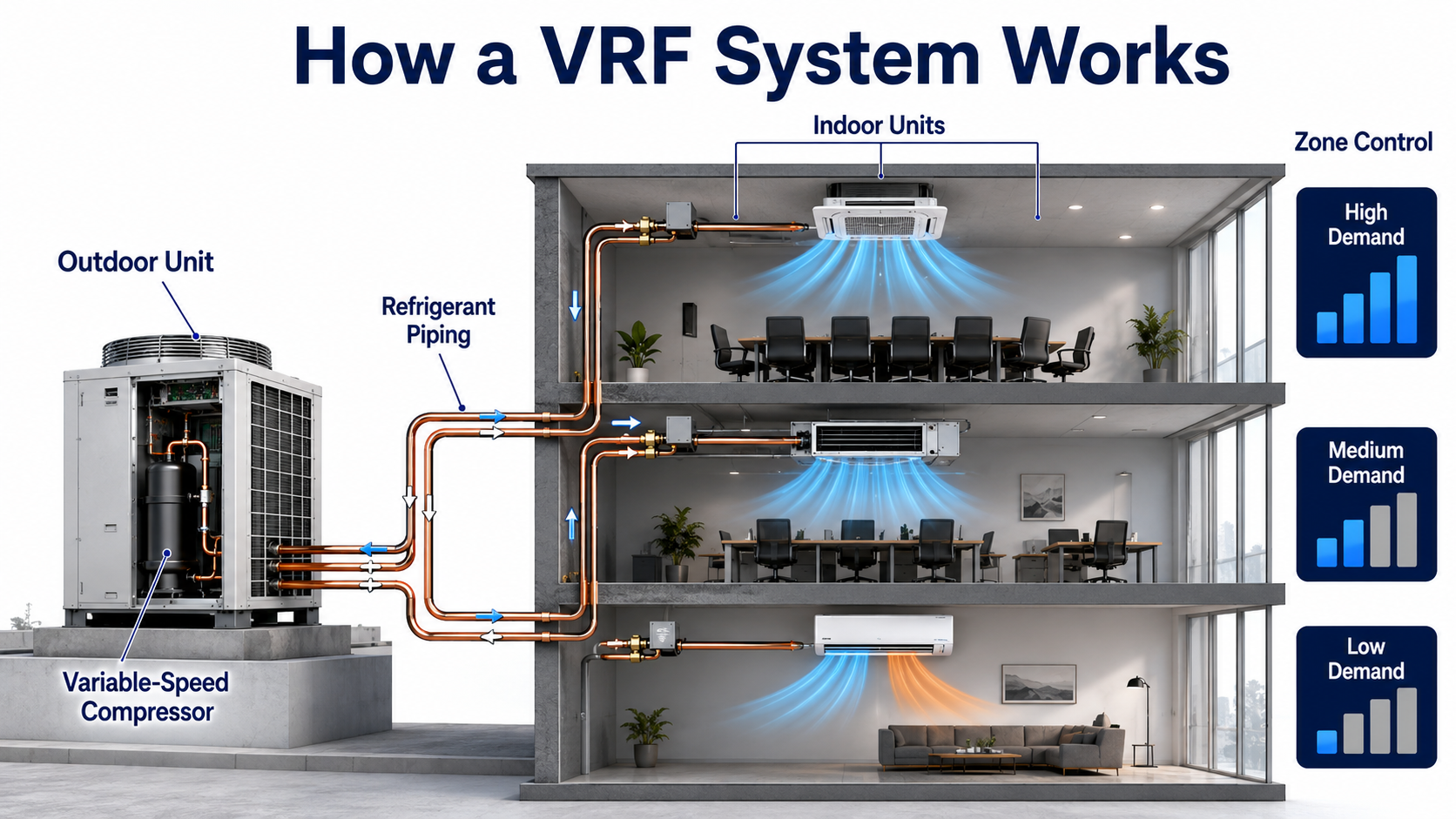
A VRF system does not simply switch one fixed-capacity compressor on and off. Indoor units continuously report demand, electronic expansion valves regulate refrigerant at each zone, and the outdoor unit adjusts compressor output to match the active building load.
VRF Systems at a Glance
Most readers can understand VRF by separating the system into three decisions: how capacity changes, how zones are connected, and whether zones can operate in opposing modes.
Variable Capacity
The outdoor unit changes compressor output instead of operating only at full capacity. This allows the system to respond to the combined demand of all connected indoor units.
Multiple Independent Zones
Each indoor unit has local sensing, airflow control, and refrigerant metering. One room can require high cooling while another room on the same system requires very little capacity.
Heat Pump or Heat Recovery
Heat-pump VRF provides either heating or cooling to connected zones. Heat-recovery VRF adds refrigerant-routing hardware so some zones can cool while others heat.
If the connected rooms normally need the same operating mode, heat-pump VRF may be sufficient. If meaningful opposing loads occur frequently, heat-recovery VRF deserves closer evaluation.
How Variable Refrigerant Flow HVAC Operates
A VRF system uses the same basic vapor-compression cycle found in air conditioners and heat pumps. Refrigerant absorbs heat at a low temperature, the compressor raises its pressure and temperature, and another heat exchanger rejects that heat. VRF differs in how it distributes refrigerant among many indoor units and continuously adjusts capacity.
Zone Demand and Capacity Control
Each indoor unit senses its local room condition and compares it with the zone setpoint. An electronic expansion valve regulates refrigerant through the indoor coil, while the indoor fan adjusts airflow according to the control sequence. The outdoor unit evaluates the combined demand from all active indoor units and varies compressor capacity accordingly.
- A zone near its setpoint may receive very little refrigerant and operate at reduced fan speed.
- A high-load zone may open its expansion valve further and request more capacity.
- The outdoor compressor responds to total connected demand rather than one room alone.
- Indoor units can have separate setpoints even when they share an outdoor refrigeration circuit.
Cooling Operation
During cooling, the outdoor heat exchanger rejects heat to outdoor air or a water loop. High-pressure liquid refrigerant travels toward the indoor units, where individual electronic expansion valves reduce its pressure. The refrigerant evaporates inside active indoor coils, absorbs heat from room air, and returns to the compressor as vapor.
The expansion valves do not have to open equally. A crowded conference room may require substantially more cooling than a lightly occupied office, so the system distributes capacity according to the connected zone demand.
Heating Operation
During heating, the refrigeration cycle reverses. The indoor coils act as condensers and release heat into occupied zones, while the outdoor coil absorbs heat from outdoor air or the connected water loop. The compressor and indoor metering devices continue to modulate as zone loads change.
Air-source heating performance depends on outdoor temperature and humidity. Frost can accumulate on the outdoor coil during some heating conditions, requiring a defrost cycle. Heating capacity, defrost behavior, electrical demand, and any supplemental heat requirement must be checked at the project design conditions.
The word “variable” describes more than compressor speed. The system coordinates compressor capacity, outdoor fans, indoor expansion valves, indoor fans, and control targets as building demand changes.
Main Components of a VRF System
A reliable VRF installation depends on several coordinated components. Outdoor and indoor units receive most of the attention, but piping design, branch devices, communication wiring, drainage, and service access are equally important.
Outdoor Unit and Compressors
The outdoor unit contains one or more compressors, a heat exchanger, fans or a water-side heat exchanger, refrigerant-management components, sensors, and electronic controls. Variable-speed scroll or rotary compressors are commonly used because they can adjust capacity across a broad operating range.
Indoor Units
Indoor units contain a refrigerant coil, fan, filter, electronic expansion valve, sensors, control board, and condensate provisions. Common arrangements include:
- Ceiling cassettes: Recessed into a suspended ceiling and capable of distributing air in several directions.
- Concealed ducted units: Installed above a ceiling or in a service area and connected to short duct runs.
- Wall-mounted units: Exposed terminals commonly used where ceiling space is limited.
- Ceiling-suspended units: Surface-mounted units used in spaces without suitable ceiling cavities.
- Floor-standing units: Positioned near floor level for perimeter or retrofit applications.
Electronic Expansion Valves
An electronic expansion valve regulates refrigerant entering an indoor coil. By changing valve position, the control system can increase or reduce the capacity delivered to that zone while maintaining the refrigerant conditions required by the system.
Refrigerant Piping and Branch Devices
Refrigerant piping connects the outdoor system to multiple indoor units. Factory-approved branch joints, headers, or controllers divide and redirect refrigerant flow. Pipe sizes, equivalent lengths, elevation differences, oil-return requirements, insulation, allowable connected capacity, and refrigerant charge are manufacturer-specific.
Controls and Communication
VRF controls link indoor units, outdoor units, branch controllers, local thermostats, and central controllers. Building automation integration may be available through gateways, but control points, sequences, alarm handling, schedules, and ownership of commands must be coordinated during design.
Condensate and Drainage
Cooling indoor units remove moisture from the air, so each unit needs a correctly sloped drain or an approved condensate-pump arrangement. Drain pans, pumps, float switches, cleanouts, insulation, and service access should be considered before ceilings are closed.
Types of Variable Refrigerant Flow Systems
VRF systems are generally classified as cooling-only, heat-pump, or heat-recovery systems. Cooling-only configurations provide cooling without reverse-cycle heating. Most system-selection decisions focus on the difference between heat-pump and heat-recovery VRF.

Cooling-Only VRF
Cooling-only systems serve applications that do not require reverse-cycle heating, such as certain equipment spaces, process rooms, or projects with a separate heating source. They retain multi-zone capacity modulation but do not reverse the refrigeration cycle for space heating.
Heat-Pump VRF
Heat-pump VRF can provide either heating or cooling to connected indoor units. Each zone may have its own setpoint and capacity response, but all units on the applicable system must generally operate in the same overall mode at a given time.
This arrangement is often appropriate when connected spaces have similar exposures, schedules, and seasonal load patterns. It is simpler than heat recovery because it does not need the same level of refrigerant-routing hardware.
Heat-Recovery VRF
Heat-recovery VRF can provide simultaneous heating and cooling. The system redirects energy from zones requiring cooling toward zones requiring heating, while the outdoor unit handles the remaining imbalance between total heating and cooling loads.
Heat recovery is most valuable when opposing loads occur frequently—for example, an interior conference room needing cooling while a shaded perimeter office needs heating. It adds branch controls, piping considerations, commissioning requirements, first cost, and service complexity.
Two-Pipe and Three-Pipe Heat Recovery
Both two-pipe and three-pipe heat-recovery architectures are available. A two-pipe system may use a branch controller containing valves, separators, and heat-exchange components. A three-pipe system typically carries high-pressure vapor, low-pressure vapor, and liquid between the outdoor unit and refrigerant-control devices.
Do not assume every two-pipe VRF system is heat-pump-only or that heat recovery always requires three pipes. Piping architecture and branch-device operation vary by manufacturer.
How VRF Heat Recovery Transfers Heat Between Zones
Heat recovery does not move room air directly between spaces. Refrigerant carries thermal energy through the system, and a branch controller or similar device routes the refrigerant states required by indoor units operating in different modes.

A zone in cooling mode absorbs room heat into the refrigerant. Instead of rejecting all of that energy outdoors, a heat-recovery system can make part of it available to a zone in heating mode. The outdoor heat exchanger remains part of the process whenever the building’s total heating and cooling demands are not balanced.
Balanced and Unbalanced Loads
Perfectly balanced heat recovery is uncommon for long periods. If cooling demand exceeds heating demand, the outdoor unit must reject the excess heat. If heating demand exceeds available recovered heat, the outdoor unit must absorb additional heat from outdoor air or the connected water loop.
Where Opposing Zone Loads Occur
- Interior spaces with high equipment or occupant gains while perimeter rooms require heat
- East- and west-facing zones exposed to solar gain at different times of day
- Hotels and multifamily buildings with independent occupancy and setpoints
- Mixed-use buildings with different operating schedules
- Shoulder seasons when outdoor temperature and solar exposure shift throughout the day
Heat recovery should be justified by hourly or seasonal zone-load patterns. Peak heating and cooling calculations alone may not reveal whether simultaneous opposing loads occur often enough to matter.
VRF Advantages and Limitations
VRF can solve difficult zoning and distribution problems, but its value depends on the building. The comparison below pairs each potential advantage with the condition that can limit its usefulness.
| Characteristic | Potential advantage | Important limitation or condition |
|---|---|---|
| Individual zone control | Rooms can have separate setpoints and capacity responses. | Heat-pump systems still require connected zones to share one general operating mode. |
| Variable capacity | Compressor output can follow changing part-load demand. | Performance depends on correct sizing, controls, outdoor conditions, and installation quality. |
| Reduced large ductwork | Refrigerant piping may require less shaft and ceiling space than central-air ducts. | Ventilation, exhaust, filtration, and humidity control may still require duct systems. |
| Heat recovery | Recovered energy can serve zones with opposing loads. | The value depends on how often meaningful simultaneous heating and cooling occurs. |
| Indoor-unit flexibility | Different terminal styles can serve different room layouts. | Air distribution, noise, maintenance access, and condensate routing must be checked for each unit. |
| Modular equipment | Systems can be divided by floor, tenant, wing, or operating schedule. | More equipment and control networks can increase coordination and service complexity. |
| Refrigerant distribution | Small piping can offer flexible routing through a building. | Piping length, elevation, charge, oil return, leak response, and concentration require detailed review. |
| Air-source heating | Can provide reversible heating without a central boiler in suitable applications. | Low-temperature capacity, defrost, backup heat, and electrical demand must be evaluated. |
VRF should be compared with realistic alternatives at the same design conditions. A system with strong rated part-load performance can still be a poor project choice if ventilation, service access, cold-weather heating, refrigerant safety, or owner maintenance capability remains unresolved.
Ventilation, Humidity, and Indoor Air Quality
Many VRF indoor units recirculate room air and do not independently provide the outdoor airflow required for occupied spaces. A complete design must coordinate zone conditioning with ventilation rates, exhaust, building pressure, filtration, and moisture control.
Dedicated Outdoor-Air System
A dedicated outdoor-air system, commonly called a DOAS, conditions and distributes outdoor ventilation air separately from the zone sensible-cooling and heating equipment. This arrangement allows the ventilation system to manage outdoor-air temperature and moisture while VRF indoor units respond to local zone loads.
Energy-Recovery Ventilation
An energy-recovery ventilator can transfer sensible energy and, depending on the device, moisture between exhaust and incoming outdoor airstreams. Energy recovery can reduce the outdoor-air load but does not eliminate the need to size ventilation equipment for the applicable climate, occupancy, and operating schedule.
Latent-Load Control
Low sensible loads do not always mean low moisture loads. A zone may need dehumidification even when its temperature is close to setpoint. Designers should evaluate coil leaving conditions, ventilation-air dew point, indoor fan operation, condensate disposal, and any need for supplemental dehumidification or reheat.
Filtration and Air Cleaning
Small indoor VRF units may not provide the same filtration capacity or pressure capability as a central air handling unit. Filter efficiency, replacement access, pressure drop, outdoor-air treatment, and any project-specific air-cleaning requirements must be coordinated across the entire HVAC system.
A room can maintain the thermostat setpoint and still feel humid or have poor indoor air quality. Temperature control alone does not confirm that ventilation and latent loads are being handled correctly.
VRF System Selection: Heat Pump or Heat Recovery?
Use this workflow as an early system-screening tool. It helps identify which VRF architecture deserves further analysis, but it does not replace room-by-room HVAC load calculations, energy modeling, code review, or manufacturer selection software.
- Calculate zone loads: Determine heating and cooling requirements by room or thermal zone, including envelope, solar, occupancy, equipment, lighting, ventilation, and schedule effects.
- Identify opposing loads: Check whether meaningful heating and cooling demands occur at the same time, not merely on different days or seasons.
- Group compatible zones: Combine spaces with similar exposures, uses, schedules, operating modes, and control expectations.
- Screen heat-pump VRF: Use heat-pump VRF where connected zones normally require the same system mode and simultaneous operation has little value.
- Screen heat-recovery VRF: Consider heat recovery where interior and perimeter zones, different occupancies, or mixed schedules frequently create opposing loads.
- Verify project constraints: Review connected capacity, piping length, elevation, refrigerant concentration, climate performance, ventilation, electrical service, controls, acoustics, condensate, and service access.
- Compare alternatives: Evaluate installed cost, annual energy, maintenance, replacement strategy, and operating capability against VAV, packaged, hydronic, and conventional split systems.
Practical Selection Example
Consider a three-story office with open perimeter workspaces, interior conference rooms, and a first-floor training area. The perimeter zones generally follow outdoor weather, while the conference and training rooms experience short periods of high occupant and equipment load.
If the connected zones normally switch between heating and cooling together, heat-pump VRF may provide the required zoning with less refrigerant-control complexity. If occupied interior rooms regularly require cooling while shaded perimeter rooms require heating, heat-recovery VRF may justify its additional branch controls and commissioning effort. Hourly load profiles—not floor area alone—should support the decision.
Do not select heat recovery simply because simultaneous heating and cooling is possible. Confirm that opposing loads occur often enough and at sufficient magnitude to improve comfort or operating performance.
VRF Design Review Checklist
- Room-by-room heating and cooling loads are documented.
- Zones are grouped by exposure, use, schedule, and expected operating mode.
- Indoor units are selected for capacity, turndown, airflow, throw, noise, and access.
- Outdoor performance is checked at project heating and cooling design conditions.
- Connected-capacity and diversity limits follow current manufacturer requirements.
- Pipe sizes, equivalent lengths, fittings, elevation, insulation, and oil return are verified.
- Refrigerant charge and concentration are reviewed for occupied rooms and applicable requirements.
- Ventilation, exhaust, filtration, building pressure, and latent loads are coordinated.
- Condensate drains and pumps are accessible and testable.
- Controls, addressing, monitoring, alarms, schedules, and BAS integration are defined.
- Indoor and outdoor service clearances are maintained.
- Commissioning includes cooling, heating, mode change, heat recovery, alarms, and failure response.
Where VRF Systems Work Best
VRF is usually strongest where a building needs many independently controlled zones, has limited space for large ductwork, or experiences load diversity that variable capacity can serve effectively.
Hotels and Multifamily Buildings
Guest rooms and apartments have independent schedules and setpoints. Small indoor units can serve individual spaces, while common areas can use different terminal types. Designers must still address ventilation, bathroom exhaust, kitchen exhaust where applicable, acoustics, condensate, refrigerant concentration, and access without entering occupied units unnecessarily.
Offices and Mixed-Use Buildings
Perimeter offices, interior conference rooms, retail areas, and tenant spaces can have very different loads. Heat recovery may be useful where these differences create recurring simultaneous heating and cooling.
Schools and Institutional Buildings
Classrooms, administration areas, libraries, and multipurpose rooms may benefit from independent schedules and modular operation. Outdoor-air volume, filtration, occupancy variation, controls access, maintenance staffing, and equipment location require careful planning.
Retrofits and Historic Buildings
Small refrigerant piping can be easier to route than large supply and return ducts in space-constrained renovations. The distribution advantage must be balanced against refrigerant charge, fire and smoke coordination, equipment access, condensate routing, electrical upgrades, and preservation requirements.
When Another HVAC System May Be Better
- The building has simple, uniform loads that do not justify extensive zone controls.
- Ventilation or process-air requirements dominate the HVAC design.
- A central chilled-water or hot-water plant better fits the building scale and owner operations.
- Qualified VRF installation and service support is limited in the project area.
- Refrigerant concentration or leak-management requirements make the intended zoning impractical.
- Owner standards prioritize standardized central equipment and long-term component interchangeability.
Building type is only a starting point. Final suitability depends on actual loads, climate, ventilation strategy, owner requirements, refrigerant planning, electrical infrastructure, service resources, and lifecycle objectives.
VRF Compared With Other HVAC Systems
This comparison focuses on architecture and application differences rather than declaring one universal winner.
| System | Distribution method | Zoning approach | Best-fit conditions | Main design concern |
|---|---|---|---|---|
| VRF | Refrigerant piping to multiple indoor units | Individual indoor-unit control with variable capacity | Multi-zone buildings with diverse loads and limited large-duct space | Refrigerant design, ventilation integration, controls, and qualified service |
| Ductless mini-split | Refrigerant piping to one or a small group of indoor units | Room or small-zone control | Homes, additions, small commercial areas, and isolated zones | Limited scale, aesthetics, ventilation, and multiple outdoor units |
| Rooftop unit with VAV | Central conditioned air through ductwork | Airflow modulation at terminal units | Commercial buildings suited to central ventilation and air distribution | Duct space, fan energy, terminal minimums, simultaneous loads, and controls |
| Conventional split system | Refrigerant piping between matched indoor and outdoor equipment | Single zone or limited zoning | Simple buildings and zones with aligned loads | Limited multi-zone flexibility and part-load strategy |
| Chilled-water system | Water piping to coils or terminal units | Central plant with air-side or water-side zone control | Large buildings, campuses, and owners with central-plant expertise | Plant complexity, pumps, water treatment, controls, and capital cost |
VRF Versus a Mini-Split
Both are direct-expansion systems, but VRF generally supports more indoor units, longer and more complex piping networks, broader control integration, and larger commercial applications. A mini-split may be more appropriate where only one or a few zones need independent conditioning.
VRF Versus VAV
A variable air volume system distributes conditioned air from central equipment and varies airflow to zones. VRF moves refrigerant closer to the zones and usually separates outdoor-air delivery from local sensible conditioning. VAV may be advantageous where central ventilation, filtration, airside economizing, and common air systems align with the project.
VRF Versus a Conventional Heat Pump
A conventional heat pump system commonly serves one zone or a limited duct system. VRF extends the reversible heat-pump concept across multiple indoor units with variable capacity, individual metering, networked controls, and optional heat recovery.
VRF Versus Chilled Water
VRF circulates refrigerant through occupied-building piping, while chilled-water systems circulate water to coils and concentrate much of the refrigeration equipment in a central plant. Chilled water often fits large buildings and campuses with central operations staff, while VRF may fit modular buildings that value decentralized zone control.
Installation, Commissioning, and Common VRF Problems
VRF performance depends heavily on field execution. A well-selected system can underperform when piping, charging, controls, drainage, airflow, or commissioning is incomplete.
Installation Priorities
- Pipe cleanliness: Keep refrigerant tubing sealed and free of moisture, dirt, scale, and foreign material.
- Brazing procedure: Follow approved practices, including nitrogen flow where required to limit internal oxidation.
- Branch orientation: Install branch joints and controllers in permitted positions with required straight lengths and service access.
- Pressure testing: Test the completed piping according to current equipment and project requirements before evacuation.
- Evacuation and charging: Verify dehydration and calculate additional refrigerant charge from the actual installed piping.
- Insulation: Insulate refrigerant lines and joints to prevent unwanted heat transfer and surface condensation.
- Condensate: Test gravity drains and pumps under realistic operating conditions.
Commissioning Checks
Commissioning should confirm equipment addressing, communication, sensor readings, indoor airflow, local controls, central controls, mode selection, heat recovery, defrost behavior where practical, alarms, condensate disposal, and integration with ventilation and building automation systems.
Common VRF Problems and First Checks
- Uneven room temperature: Check load assumptions, indoor-unit selection, airflow pattern, filter condition, sensor location, valve operation, and zone-control settings.
- Indoor unit will not operate: Check system-mode conflicts, communication addressing, controller permissions, alarm history, power, and interlocks.
- Insufficient heating: Review outdoor conditions, available equipment capacity, defrost operation, connected load, airflow, supplemental heat, and refrigerant condition.
- Condensate leakage: Inspect drain slope, traps, pumps, float switches, insulation, coil cleanliness, and construction debris.
- Communication alarm: Check control wiring topology, polarity where applicable, shielding, grounding, addressing, connectors, and controller configuration.
- High energy use: Review schedules, setpoint conflicts, ventilation loads, dirty heat exchangers, refrigerant charge, compressor operation, and control overrides.
- Refrigerant alarm or suspected leak: Follow the approved safety and service procedure, locate and repair the leak, test the system, evacuate as required, and restore the correct charge rather than repeatedly adding refrigerant.
Many apparent equipment failures originate in controls, airflow, drainage, piping, or commissioning. Diagnostic work should review the complete system instead of replacing components based only on one alarm code.
Variable Refrigerant Flow Engineering References
These references support the definitions, system classifications, operating concepts, components, applications, and design qualifications described on this page.
- ASHRAE Handbook Chapter 18: Variable Refrigerant Flow Supports VRF system types, components, zone control, ventilation integration, heat recovery, two-pipe and three-pipe architectures, applications, operation, and design considerations.
- U.S. Department of Energy: Variable Refrigerant Flow Air Conditioners and Heat Pumps Supports the federal equipment definition, variable-capacity requirements, common refrigerant circuit, multiple indoor fan coils, individual metering, and integrated controls.
Frequently Asked Questions
Heat-recovery VRF can heat and cool different zones simultaneously by routing refrigerant through branch-control equipment. Standard heat-pump VRF allows individual zone setpoints, but connected indoor units generally operate in the same overall heating or cooling mode.
Not necessarily. Many VRF indoor units recirculate room air, so required outdoor ventilation commonly comes from a dedicated outdoor-air system, energy-recovery ventilator, air-handling unit, or another separately designed ventilation system.
Both use refrigerant piping and direct-expansion indoor units, but VRF generally serves more zones with a larger shared network, variable-capacity control, centralized communications, more indoor-unit options, and heat-recovery capability on applicable systems.
VRF can perform effectively at part load and in buildings with diverse zone demands, but actual performance depends on climate, sizing, controls, ventilation loads, heat-recovery opportunities, installation quality, maintenance, and the alternative system used for comparison.
VRF is the generic term for variable refrigerant flow technology. VRV, meaning variable refrigerant volume, is a trademarked manufacturer name for equipment using the same general category of multi-zone variable-capacity refrigeration technology.
Summary and Next Steps
A variable refrigerant flow system uses variable-capacity compression, common refrigerant piping, individually metered indoor units, and integrated controls to serve multiple HVAC zones. Heat-pump VRF places connected zones in one general operating mode, while heat-recovery VRF can redirect energy between zones that need opposing modes.
The central design question is not simply whether VRF can serve the building. It is whether the selected VRF architecture fits the actual zone-load patterns, ventilation strategy, climate, refrigerant requirements, controls, service capability, and lifecycle objectives.
Where to Go Next
-
Heat Pump System
Review the reversible refrigeration process that allows VRF equipment to provide both heating and cooling.
-
Variable Air Volume System
Compare refrigerant distribution with a central-air system that controls zones by varying airflow.
-
Vapor Compression Cycle
Review the compressor, condenser, expansion, and evaporation processes underlying VRF operation.