
Table of Contents
Introduction
HVAC air balancing is the process of measuring and adjusting supply, return, exhaust, and outdoor airflow so an installed system operates as closely as practical to its design requirements. Proper balancing delivers the intended airflow to each room while supporting comfort, ventilation, pressure control, equipment performance, and reliable operation.
Air balancing is one part of testing, adjusting, and balancing, commonly called TAB. It verifies actual system performance, corrects adjustable conditions, identifies deficiencies, and documents the final operating condition. It does not replace correct equipment sizing, duct design, controls, commissioning, maintenance, or repair.
Key Takeaways
- Primary goal: Deliver the required airflow to each branch, zone, and terminal rather than making every outlet equal.
- Correct sequence: Verify system readiness and total fan airflow before adjusting individual diffusers or branch dampers.
- Core measurements: TAB work may include airflow, velocity, static pressure, fan speed, outdoor air, exhaust air, and room-pressure relationships.
- Critical limitation: Dampers redistribute available airflow but cannot correct inadequate fan capacity, severe restrictions, failed controls, or major leakage.
What HVAC Air Balancing Changes
An unbalanced system may deliver excessive airflow to low-resistance branches while remote or restrictive branches receive too little. Balancing corrects the distribution so each space approaches its assigned airflow target.
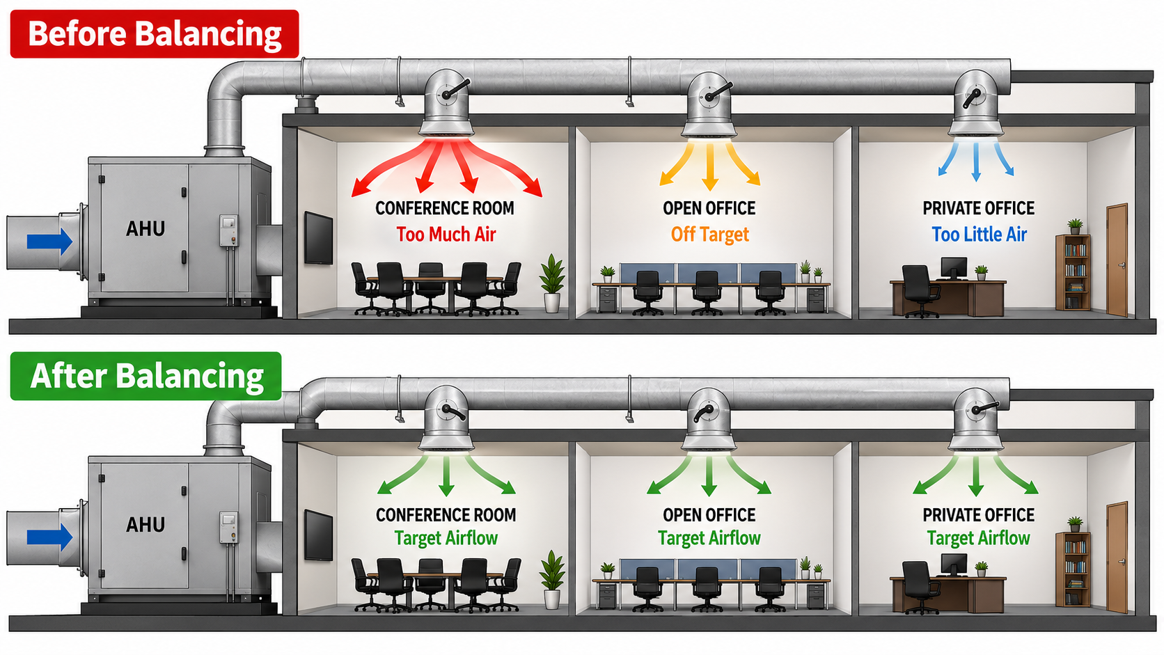
A successful result depends on adequate total fan airflow. If the fan cannot produce the required total, terminal adjustments can only redistribute the shortage.
What HVAC Air Balancing Includes
Air balancing compares measured performance with values shown on approved drawings, schedules, specifications, submittals, control sequences, commissioning documents, or other project criteria. The technician then adjusts intended balancing devices and verifies the resulting system condition.
A typical air-balancing scope may include:
- Total supply airflow from an air-handling unit, rooftop unit, or supply fan
- Airflow through main ducts and major branch ducts
- Airflow through constant-volume or variable-air-volume terminal units
- Supply airflow from diffusers, registers, and grilles
- Return airflow from rooms, zones, and central return paths
- General exhaust, process exhaust, or relief airflow
- Outdoor airflow used for ventilation or building pressurization
- Pressure relationships between rooms and adjacent spaces
- Fan speed, drive condition, and variable-frequency-drive output
- Damper positions, terminal setpoints, and relevant control settings
Testing, Adjusting, and Balancing
Testing establishes the actual operating condition through measurements. Adjusting changes controllable devices or settings. Balancing proportionally distributes airflow or hydronic flow. Final verification confirms and documents the completed operating condition.
Air Balancing Versus Commissioning
Air balancing focuses on measured flow, pressure, equipment operation, distribution, and related adjustments. Commissioning has a broader scope that may verify design intent, installation, controls, sequences, functional performance, training, and documentation. TAB data often supports commissioning, but the processes are not interchangeable.
Air Balancing Versus Duct Cleaning
Duct cleaning removes accumulated material from accessible system components. Air balancing measures and adjusts airflow. Dirty filters, obstructed coils, or contaminated equipment can affect airflow, but cleaning and balancing remain separate activities.
A room that feels uncomfortable does not automatically need more airflow. The cause may involve room load, humidity, thermostat location, diffuser selection, air mixing, solar exposure, controls, or equipment operation.
HVAC Air Balancing Readiness Checklist
Balancing should begin after the system can operate in a stable and representative condition. Testing an incomplete or malfunctioning system produces unreliable readings and repeated field work.
Construction and Installation
- Ductwork, fittings, access doors, terminal units, diffusers, grilles, and registers are installed.
- Duct sealing and insulation are substantially complete.
- Flexible ducts are connected, supported, and free of severe compression or kinks.
- Fire, smoke, control, isolation, and balancing dampers are installed and accessible.
- Ceilings, doors, walls, partitions, and other elements affecting airflow paths are in place.
- Construction debris, temporary filters, and shipping restraints have been removed.
Equipment
- Fans rotate in the correct direction and operate without abnormal vibration.
- Belts, sheaves, couplings, and drives are installed and serviceable.
- Filters are installed and reasonably clean.
- Heating and cooling coils are clean and unobstructed.
- Fan motors, variable-frequency drives, and protective devices are operational.
- Outdoor-air, return-air, relief-air, and exhaust components can move through their intended ranges.
Controls
- Temperature, airflow, pressure, and position sensors are installed and functional.
- Terminal units can be commanded to required maximum and minimum positions.
- Fan speed and static-pressure controls can maintain a stable test condition.
- Economizer, demand-control ventilation, occupancy, and pressure-control modes are understood.
- Interlocks and operating sequences allow testing in the required mode.
A damper adjustment should not be used to conceal a closed fire damper, disconnected duct, failed actuator, dirty coil, incorrect fan rotation, collapsed flexible duct, or incomplete control sequence.
HVAC Air Balancing Process
A reliable balancing sequence moves from the air source toward the terminal devices. The process is iterative because each adjustment changes resistance and can affect airflow elsewhere.

- Review design requirements: Identify required fan, branch, terminal, return, exhaust, and outdoor-air quantities from approved project information.
- Inspect system readiness: Verify that equipment, filters, coils, dampers, ducts, terminals, outlets, and controls are ready for testing.
- Establish the test mode: Operate the system under the condition required by the project procedure, specification, or control sequence.
- Allow operation to stabilize: Avoid final readings while fan speed, static pressure, damper position, or terminal airflow is changing.
- Measure fan performance: Record total airflow, fan speed, motor condition, control output, and required static pressures.
- Verify available airflow: Determine whether the fan produces enough airflow to support downstream design quantities.
- Measure mains and branches: Establish how airflow is distributed among major portions of the system.
- Identify the index path: Locate the branch or outlet with the lowest measured-to-design airflow ratio in the group being balanced.
- Proportionally adjust branches: Reduce stronger paths toward the index path’s percentage while preserving adequate total airflow.
- Balance terminal devices: Measure terminal units, diffusers, registers, and grilles and adjust intended upstream balancing devices.
- Verify return, exhaust, and outdoor air: Confirm that supply adjustments have not created unacceptable airflow or pressure conditions.
- Recheck interacting readings: Repeat critical measurements after significant adjustments because airflow paths interact.
- Record deficiencies: Document conditions that prevent the system from reaching its required performance.
- Complete the TAB report: Record design values, final readings, equipment data, settings, instruments, and unresolved deviations.
Do not begin by closing every high-flow diffuser. Confirm total fan airflow and main-duct distribution first. Otherwise, outlet adjustments may redistribute a system-wide shortage rather than resolve it.
HVAC Air Balancing Tools and Measurements
No single instrument is correct for every measurement. Tool selection depends on duct or terminal geometry, expected velocity, airflow pattern, access, required accuracy, and whether the test involves flow, pressure, speed, or room pressurization.

| Tool or method | Primary measurement | Typical application | Important limitation |
|---|---|---|---|
| Flow hood | Terminal airflow | Supply and return diffusers, registers, and grilles | The hood and terminal discharge pattern can affect the reading |
| Pitot tube and differential manometer | Velocity pressure and duct airflow | Main or branch duct traverse | Requires an appropriate traverse pattern and representative test location |
| Hot-wire anemometer | Air velocity | Low-velocity openings, grilles, coils, and ducts | A single point may not represent average velocity |
| Rotating-vane anemometer | Air velocity | Larger openings, grilles, and face-velocity measurements | Probe area, orientation, and traverse method affect the result |
| Static-pressure probe | Duct or component static pressure | Fans, filters, coils, ducts, and terminal units | Incorrect probe location or orientation can distort the reading |
| Differential-pressure meter | Pressure difference | Rooms, filters, coils, fans, and connected spaces | The reference point and operating condition must be defined |
| Tachometer | Fan or motor rotational speed | Fan and drive verification | Rotational speed alone does not establish airflow |
Duct Traverse
A duct traverse samples velocity pressure or velocity at multiple points across a duct cross-section. The readings are averaged and combined with the measured duct area to estimate volumetric airflow. The best available location should be selected away from severe elbows, transitions, dampers, or other disturbances.
Flow-Hood Testing
A flow hood captures air passing through a terminal device and reports an estimated airflow. Flow hoods are efficient for many outlets, but swirl, low velocity, large diffusers, leakage around the hood, and device-specific discharge patterns can affect the result.
Static-Pressure Testing
Static-pressure measurements help identify resistance across filters, coils, ducts, dampers, and terminal devices. They also help determine whether a fan is operating under the expected system condition and why airflow may differ from design.
Instrument Range and Calibration
The selected instrument should have a suitable range and resolution for the expected condition. Instruments should be inspected, maintained, and calibrated according to the applicable procedure and the balancing provider’s quality requirements.
HVAC Air Balancing Formulas
Balancing instruments may calculate airflow automatically, but basic equations remain useful for checking measurements, converting average velocity to airflow, and comparing actual performance with design values.
Airflow from Area and Average Velocity
- \(Q\) Volumetric airflow, commonly expressed in cfm, m³/s, or L/s.
- \(V_{\mathrm{avg}}\) Average air velocity across the measured area, commonly expressed in ft/min or m/s.
- \(A\) Open cross-sectional area normal to airflow, commonly expressed in ft² or m².
The velocity must represent the cross-sectional average. A single centerline reading should not replace a traverse unless the measurement method and airflow profile justify that approach.
Percent of Design Airflow
- \(Q_{\mathrm{measured}}\) Measured airflow at the fan, duct, branch, terminal unit, diffuser, register, or grille.
- \(Q_{\mathrm{design}}\) Required airflow from approved project documents or operating criteria.
- 100% The measured value equals the stated target before applying project-specific acceptance requirements.
Proportional Airflow Ratio
The ratio \(R_i\) compares each outlet or branch with its own target. A 200 cfm outlet measuring 160 cfm and a 500 cfm branch measuring 400 cfm are both operating at 80% of design, even though their raw airflow values differ.
Simplified Room Airflow Accounting
This relationship is a simplified accounting check for intentional airflow paths. A positive difference may support positive pressure, while a negative difference may support negative pressure. It does not directly predict room pressure because leakage, door position, wind, stack effect, adjacent spaces, and connected systems also influence the result.
Do not assume one universal allowable percentage from design. Acceptance criteria should come from the project specifications, contract documents, commissioning requirements, or applicable TAB standard.
Proportional Air Balancing Example
Consider a supply branch serving three diffusers. The required branch airflow is 900 cfm, divided among the outlets according to their room airflow requirements.
| Outlet | Design airflow | Initial measured airflow | Initial percent of design |
|---|---|---|---|
| Diffuser A | 200 cfm | 220 cfm | 110% |
| Diffuser B | 300 cfm | 255 cfm | 85% |
| Diffuser C | 400 cfm | 300 cfm | 75% |
| Branch total | 900 cfm | 775 cfm | 86.1% |
1. Check the Total-Airflow Shortage
The branch provides only 775 cfm against a 900 cfm target. Closing Diffuser A cannot create the missing 125 cfm. Before final outlet balancing, the technician should investigate the upstream damper, terminal setting, duct condition, fan operation, static pressure, leakage, and total available airflow.
2. Find the Index Outlet
The initial airflow ratios are 1.10 for Diffuser A, 0.85 for Diffuser B, and 0.75 for Diffuser C. Diffuser C has the lowest measured-to-design ratio and is the initial index outlet for this branch.
3. Correct the Upstream Condition
Assume an upstream restriction is corrected and the branch can now provide approximately its required total airflow. Every outlet should be measured again because correcting the upstream condition changes the entire distribution.
4. Proportion the Outlet Ratios
Stronger outlets are adjusted using the intended balancing devices until their measured-to-design ratios are reasonably aligned. The index path is generally left as open as practical while stronger paths are reduced toward it.
5. Verify the Final Readings
Assume the final measurements are 202 cfm at Diffuser A, 296 cfm at Diffuser B, and 398 cfm at Diffuser C. The final branch total is 896 cfm. The outlets are approximately 101%, 98.7%, and 99.5% of their respective targets.
The outlets are closely proportioned, but formal acceptance still depends on the project requirements. Fan, branch, return, exhaust, outdoor-air, and pressure measurements should be rechecked after the outlet adjustments.
Do not create excessive pressure loss merely to force one measurement to its target. Damper position, noise, available static pressure, fan energy, and interaction with other branches remain part of the final operating condition.
Air Balancing for Different HVAC Systems
The balancing strategy must match the system configuration. Constant-volume, variable-air-volume, exhaust, outdoor-air, and pressure-controlled systems do not use identical operating conditions or adjustment sequences.
Constant-Volume Systems
Constant-volume systems are generally balanced at a defined operating condition. Total fan airflow is established first, followed by main ducts, branch ducts, terminal devices, return air, exhaust air, and outdoor air as applicable.
Variable-Air-Volume Systems
Variable-air-volume systems require coordination among fan control, static-pressure control, terminal-unit maximum and minimum settings, diversity, occupancy modes, and control sequences. Terminal units may need to be commanded to defined positions before their airflow setpoints can be verified.
Maximum-flow testing, minimum-flow testing, fan-capacity testing, diversity testing, and normal operating checks answer different questions. The project documents should identify the required test conditions.
Exhaust Systems
Exhaust balancing may include fan airflow, main and branch distribution, grille or hood airflow, replacement air, room pressure, and interaction with connected supply systems. Laboratory, kitchen, toilet, industrial, and hazardous exhaust systems may require specialized procedures.
Outdoor-Air and Ventilation Systems
Outdoor-air measurement can be difficult when intake velocities are low, profiles are turbulent, dampers create uneven flow, or outdoor air mixes with return air before an accessible measurement plane. The method should fit the arrangement and required accuracy.
Pressure-Controlled Spaces
Room pressure depends on the combined effect of supply, return, exhaust, transfer, and leakage paths. A room can have the specified supply airflow and still fail its pressure requirement when exhaust, return, door leakage, transfer openings, or adjacent-space pressure is incorrect.
Pressure readings should be recorded with corresponding door positions, fan modes, terminal conditions, and connected-system status. A pressure value without its operating context may be difficult to interpret or reproduce.
HVAC Airflow Troubleshooting
Unexpected airflow should be traced from the fan through the distribution system rather than corrected through random damper changes. Start with the broadest system condition and work toward the affected branch or room.
Low Total System Airflow
- Incorrect fan rotation, speed, control signal, or variable-frequency-drive setting
- Dirty filters or obstructed heating and cooling coils
- Closed isolation, fire, smoke, control, or balancing dampers
- Excessive duct resistance or poor fitting transitions
- Duct collapse, blockage, leakage, disconnection, or construction debris
- Incorrect fan or terminal control sequence
- Fan operation at an unintended point on its performance curve
- Incorrect test mode or unstable system operation
One Room Has Low Airflow
- Closed or incorrectly positioned branch damper
- Crushed, kinked, disconnected, or excessively long flexible duct
- Incorrect terminal-unit maximum setting
- Restricted diffuser, grille, filter, or balancing device
- High-resistance branch layout or undersized duct
- Incorrect terminal neck size or device selection
- Measurement error caused by swirl, leakage, or instrument placement
Airflow Readings Are Unstable
Changing readings may result from fan-speed control, static-pressure reset, modulating terminals, economizer operation, occupancy logic, pressure-control loops, sensor error, or interaction with another system. Stabilize or define the control condition before treating the variation as a balancing deficiency.
Noise Increases After Balancing
Excessively throttled dampers, high duct velocity, high diffuser velocity, excessive system pressure, poor fittings, or unstable controls can create objectionable noise. Reaching an airflow target does not automatically mean the system is operating acceptably.
Room Pressure Is Incorrect
Check supply, return, exhaust, transfer, door position, adjacent spaces, and leakage paths together. Adjusting one supply diffuser may not correct a pressure problem caused by an exhaust imbalance or uncontrolled opening.
Do not conceal inadequate fan capacity, inaccessible devices, control failures, severe leakage, incorrect construction, or incomplete work by reporting only the outlets that meet their targets.
Residential HVAC Air Balancing
Residential air balancing follows the same basic principle as commercial TAB: verify total system airflow, measure room airflow, compare results with room requirements, make controlled adjustments, and recheck the system.
Signs a Home May Need Airflow Evaluation
- Persistent hot or cold rooms
- Weak airflow from one or more supply registers
- Excessive airflow or noise at outlets near the air handler
- Large temperature differences between rooms
- Doors moving or whistling when the system operates
- Bedrooms becoming pressurized when doors are closed
- Comfort changing after duct, equipment, or remodeling work
Should Homeowners Close Supply Registers?
Partially closing one register may change local airflow, but widespread register closure can increase duct pressure, leakage, noise, and airflow through other branches. It may also reduce airflow across the equipment. Permanent adjustments should be based on measured system and room airflow rather than comfort impressions alone.
When Balancing Cannot Solve the Problem
Balancing may not correct undersized ducts, inadequate return paths, excessive leakage, poor diffuser placement, incorrect equipment airflow, equipment-sizing problems, insulation defects, high solar gain, or control issues. These conditions may require design or installation changes.
Before requesting balancing, confirm that filters are clean, registers are open, return grilles are unobstructed, and visible flexible ducts are not disconnected or severely compressed.
HVAC Air Balancing Report Checklist
The final report should allow the owner, engineer, commissioning provider, contractor, and future service personnel to understand what was tested, how the system operated, what was adjusted, and which deviations remain.
Project and System Information
- Project, building, area, system, equipment, and test dates
- Applicable drawings, schedules, specifications, and approved revisions
- Required airflow and pressure values
- System operating mode and control condition during testing
Fan and Equipment Data
- Fan identification, type, speed, drive condition, and control setting
- Motor electrical measurements when required
- Fan inlet, discharge, and system static pressures
- Total supply, return, exhaust, and outdoor airflow as applicable
- Filter, coil, terminal, and component pressure measurements when required
Air-Distribution Data
- Design and final airflow for main ducts, branches, terminal units, diffusers, registers, and grilles
- Final balancing-device positions or settings when required
- Room and building pressure measurements where applicable
- Maximum and minimum airflow settings for variable-volume devices when required
Instrumentation and Deficiencies
- Instrument identification and calibration information required by the applicable procedure
- Measurement methods and correction factors where applicable
- Unresolved deficiencies, inaccessible components, and test limitations
- Clear distinction among measured, calculated, and design values
- Technician, firm, certification, and approval information required by the project
A future technician should be able to reproduce the accepted operating condition and identify whether later changes resulted from controls, maintenance, equipment replacement, tenant modifications, duct changes, or system deterioration.
HVAC Air Balancing References
These sources support the terminology, procedural framework, measurement principles, and documentation practices used in HVAC testing, adjusting, and balancing.
- ASHRAE Standard 111: Testing, Adjusting, and Balancing of Building HVAC Systems Provides an industry standard addressing testing, adjusting, and balancing of building HVAC systems.
- NEBB Procedural Standard for Testing, Adjusting, and Balancing of Environmental Systems Establishes systematic criteria and minimum NEBB requirements for performing and reporting TAB work.
- AABC National Standards for Total System Balance Addresses total-system balancing, design-intent verification, TAB scope, minimum standards, and procedures.
Frequently Asked Questions
HVAC air balancing measures and adjusts supply, return, exhaust, and outdoor airflow so the installed system operates as closely as practical to its approved airflow and pressure requirements.
Technicians verify readiness, measure total fan airflow, test main ducts and branches, compare terminal airflow with design values, adjust intended balancing devices proportionally, and repeat measurements until the system is stable.
Air balancing is one part of TAB. TAB also includes testing system performance, adjusting equipment and controls, verifying results, balancing hydronic systems when included, and documenting the completed operating condition.
Closing vents can redistribute some airflow but does not verify fan airflow, branch pressure, return paths, duct leakage, or equipment requirements. Excessive closure can increase pressure, leakage, noise, and equipment airflow problems.
Common tools include flow hoods, Pitot tubes, manometers, hot-wire and rotating-vane anemometers, static-pressure probes, tachometers, differential-pressure meters, electrical meters, and system-specific control tools.
Air balancing is commonly performed during new-system commissioning, after major renovations or equipment replacement, after duct or control changes, and when measured diagnosis is needed for persistent comfort, ventilation, airflow, or pressure problems.
Summary and Next Steps
HVAC air balancing verifies how much air an installed system moves and how that airflow is distributed through fans, ducts, branches, terminal units, supply outlets, returns, exhaust systems, and outdoor-air paths. Reliable balancing begins with system readiness and total fan performance before moving downstream to individual outlets.
Successful balancing requires stable operating conditions, suitable instruments, proportional adjustment, repeated verification, and clear reporting. Damper changes cannot correct inadequate fan capacity, failed controls, severe restrictions, excessive leakage, poor design, or incomplete construction.
Where to Go Next
-
Duct Size Calculator
Estimate duct area, round diameter, rectangular dimensions, velocity, and simplified pressure loss from required airflow.
-
Continuity Equation
Review the relationship among volumetric airflow, cross-sectional area, velocity, density, and conservation of mass.
-
HVAC Engineering Resources
Continue to related HVAC design, equipment, ventilation, ductwork, and air-distribution topics.