
Table of Contents
Introduction
An air handling unit, or AHU, is an enclosed HVAC assembly that mixes, filters, heats, cools, and moves air through a building. A typical AHU contains dampers, filters, coils, a fan, sensors, and controls, but its exact configuration depends on the required airflow, ventilation, humidity control, filtration, pressure, acoustics, and available space.
The AHU is one part of the larger HVAC system. It may receive chilled water from a chiller, hot water from a boiler, refrigerant from condensing equipment, or heat from an electric or steam source. The AHU treats the air and sends it through supply ductwork to occupied spaces.
Key Takeaways
- Core function: An AHU moves and conditions air; it is not the entire heating and cooling system.
- Typical air path: Outdoor air and return air mix before passing through filters, coils, a fan, and supply ductwork.
- Configuration matters: Fan location, air source, coil type, casing construction, and controls change how an AHU performs.
- Selection requires more than airflow: Static pressure, coil duties, air conditions, filtration, sound, controls, access, and maintenance must also be checked.
- Start troubleshooting at the air path: Dirty filters, fouled coils, incorrect damper positions, blocked drains, and fan problems are common causes of poor operation.
How Air Moves Through an Air Handling Unit
Most AHUs follow the same basic process even when their physical arrangements differ. Outdoor air and return air enter the unit, pass through the required treatment sections, and leave as conditioned supply air.
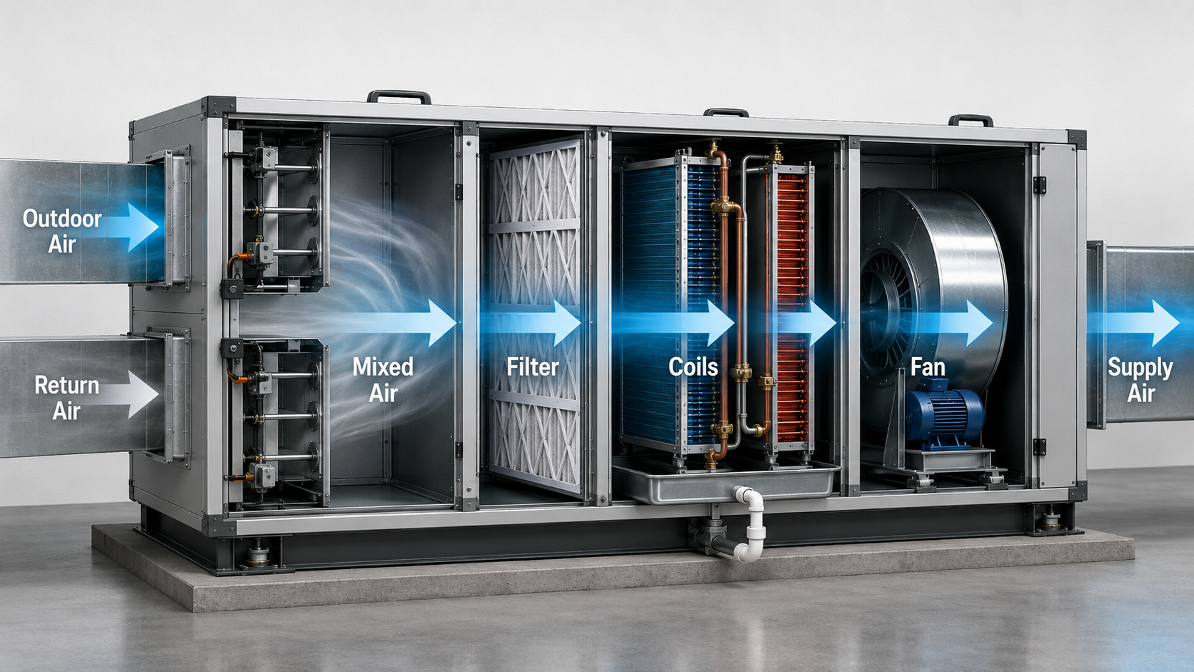
- Outdoor air enters: A controlled quantity of ventilation air enters through an intake and outdoor-air damper.
- Return air enters: Air returning from occupied spaces may be recirculated, relieved outdoors, or exhausted.
- The air streams mix: Dampers establish the outdoor-air and return-air proportions before the combined stream moves downstream.
- Filters capture particles: Filter banks protect internal equipment and provide the level of air cleaning required for the application.
- Coils change the air condition: Heating and cooling coils change temperature, while a cooling coil can also remove moisture.
- The fan creates airflow: The supply fan produces the pressure needed to move air through the AHU and connected duct system.
- Supply air leaves: The conditioned air travels through supply ductwork to terminal devices and occupied zones.
Outdoor air comes from outside, return air comes back from the building, mixed air is their combined stream, and supply air leaves the AHU. Relief air and exhaust air leave the system rather than returning to occupied spaces.
What an AHU Does—and What It Does Not Necessarily Do
An AHU brings several airside functions together inside one casing. Understanding its system boundary prevents confusion with furnaces, rooftop units, chillers, heat pumps, fan coil units, and complete HVAC systems.
Functions an AHU can perform
- Introduce and regulate outdoor ventilation air.
- Recirculate return air from occupied spaces.
- Filter particles from the air stream.
- Heat or cool air with coils or electric heating elements.
- Remove moisture when air passes over a cold cooling coil.
- Add moisture with a humidifier when required.
- Recover energy between outdoor and exhaust air streams.
- Move air through supply and return duct systems.
- Monitor and control temperature, pressure, airflow, and humidity.
Equipment the AHU may rely on
Many central-station AHUs do not independently generate chilled water or hot water. They receive heating or cooling from other equipment, such as:
- A chiller supplying chilled water
- A boiler supplying hot water or steam
- A heat pump or condensing unit supplying refrigerant
- A district heating or cooling connection
- An electric power source for resistance heating
An AHU handles the airside process. The central plant or packaged refrigeration equipment may provide the heating and cooling energy used by the AHU.
Main Air Handling Unit Components
An AHU is assembled in functional sections. Some components are found in nearly every unit, while others are included only when the application requires tighter humidity control, enhanced filtration, energy recovery, low sound, redundancy, or specialized construction.
Casing and access doors
The casing contains the air stream and supports the internal components. Its construction affects air leakage, heat transfer, condensation resistance, sound transmission, durability, and maintenance access.
Access doors must allow filters, coils, fans, dampers, sensors, and drain pans to be inspected safely. Removable panels, coil-pull space, or fan-removal paths may also be required for major repairs.
Mixing box and dampers
The mixing box receives outdoor air and return air. Dampers regulate how much of each stream enters the AHU. The arrangement may also include a relief-air damper that allows air to leave when outdoor-air intake increases.
Damper leakage, failed actuators, disconnected linkages, and incorrect control signals can cause ventilation, pressure, humidity, or temperature problems even when the fan and coils appear to operate normally.
Air filters
Filters capture particles before they reach coils, fans, ductwork, and occupied spaces. Filter efficiency must be evaluated together with pressure drop, available filter area, loading rate, bypass prevention, replacement frequency, and access.
A higher-efficiency filter may add system resistance if the filter bank and fan were not designed for it. The MERV rating guide explains how filter ratings relate to particle-size performance and HVAC system considerations.
Heating and cooling coils
Coils exchange heat between the air stream and another medium. A cooling coil may use chilled water or direct-expansion refrigerant. A heating coil may use hot water, steam, refrigerant, or electric resistance heating.
When cooling-coil surfaces are colder than the entering-air dew point, water vapor condenses on the coil. The condensate must fall into a drain pan and leave through a properly configured drain connection.
The difference between reducing air temperature and removing air moisture is covered in sensible heat versus latent heat.
Drain pan and condensate system
The drain pan collects moisture removed by the cooling coil. Pan slope, outlet location, drain piping, trap geometry, unit pressure, and cleanout access must work together so water leaves without overflowing or drawing air through the drain.
A drain arrangement that works in a positive-pressure section may not work in a negative-pressure section. Final trap dimensions should follow the actual pressure at the drain pan and the equipment manufacturer’s instructions.
Fans, motors, and drives
The fan moves the design airflow while overcoming resistance from filters, coils, dampers, internal accessories, supply ducts, return ducts, terminal equipment, and fittings. Common arrangements include housed centrifugal fans, plenum fans, and fan arrays.
Fan speed may be fixed or controlled with a variable-frequency drive. Belt-driven fans require belt, pulley, alignment, and guard maintenance. Direct-drive configurations remove the belt but still require motor, bearing, vibration, and control checks.
Sensors, actuators, and controls
AHU controls coordinate dampers, fan speed, heating valves, cooling valves, alarms, and operating modes. Typical measurements include supply-air temperature, mixed-air temperature, outdoor-air temperature, duct static pressure, filter differential pressure, humidity, airflow, and fan status.
Optional and specialized components
- Energy-recovery device: Transfers heat or moisture between exhaust and outdoor air streams.
- Humidifier: Adds moisture when the application requires a minimum humidity level.
- Sound attenuator: Reduces fan or airflow noise transmitted into ductwork.
- Final filter bank: Provides an additional filtration stage downstream of other components.
- UV equipment: May be applied for coil-surface treatment or other project-specific air-cleaning goals.
- Moisture eliminator: Helps reduce droplet carryover downstream of a wet cooling coil.
- Access section: Provides working space between components for inspection and maintenance.
A loaded filter increases pressure drop, which can reduce airflow, shift the fan operating point, reduce coil capacity, change discharge-air conditions, and make the controls respond in ways that hide the original cause.
Air Handling Unit Types and Configurations
AHUs can be classified by construction, installation location, air source, airflow control, fan position, and heating or cooling method. These classifications overlap. One unit could be an outdoor, modular, draw-through, variable-air-volume AHU with chilled-water cooling and hot-water heating.
Packaged, modular, and custom AHUs
- Packaged unit: Major heating, cooling, fan, filtration, and control components are assembled as a relatively self-contained system. A rooftop unit is a familiar packaged configuration.
- Modular AHU: Standardized sections are combined to meet the project’s airflow, filtration, coil, fan, access, and dimensional requirements.
- Custom AHU: The casing and component arrangement can be tailored for unusual dimensions, high airflow, critical environmental control, corrosion resistance, redundancy, or demanding sound criteria.
Indoor versus outdoor AHUs
An indoor AHU is normally installed in a mechanical room or penthouse. An outdoor AHU requires weather-resistant construction, suitable support, water management, freeze protection, durable seals, and safe service access for the local climate.
Recirculating, mixed-air, and 100% outdoor-air units
A recirculating AHU returns a large portion of building air to the unit. A mixed-air AHU combines return air with outdoor ventilation air. A 100% outdoor-air unit treats air drawn entirely from outdoors and may require substantial heating, cooling, dehumidification, preheat, or energy-recovery capacity.
Constant-volume and variable-air-volume operation
A constant-volume system maintains a relatively stable supply airflow and changes the delivered air condition as loads vary. A variable-air-volume system adjusts airflow to match zone demand, commonly using a variable-speed supply fan and duct static-pressure control.
Single-zone and multizone service
A single-zone AHU serves one space or group of spaces with similar operating requirements. A multizone AHU serves areas with different loads, schedules, or airflow needs through zone-level terminal equipment and controls.
Draw-Through vs Blow-Through AHUs
The terms draw-through and blow-through describe where the supply fan is located relative to the coils. Fan position affects casing pressure, leakage direction, fan heat, drainage, airflow distribution, and maintenance access.

Draw-through arrangement
In a draw-through unit, the fan is downstream of the primary coil. The fan inlet places the upstream coil and filter sections under negative pressure relative to the surrounding space. Air leakage through an imperfect casing tends to move inward in those sections.
The fan adds heat after the air leaves the cooling coil. That temperature rise must be considered when establishing the required supply-air condition. Negative pressure at the cooling-coil drain pan also makes the condensate trap and drain configuration especially important.
Blow-through arrangement
In a blow-through unit, the fan is upstream of the coil. The fan pushes air through the coil, and the downstream coil section is generally under positive pressure. Fan heat is added before the air reaches the cooling coil, allowing the coil to account for that heat before the air leaves the AHU.
Blow-through arrangements require suitable airflow distribution across the coil. Poor transitions or fan discharge conditions can create uneven coil-face velocity, increased pressure loss, noise, or moisture carryover.
| Design consideration | Draw-through AHU | Blow-through AHU |
|---|---|---|
| Fan location | Downstream of the coil | Upstream of the coil |
| Coil-section pressure | Commonly negative relative to the room | Commonly positive relative to the room |
| Fan heat | Added after the cooling coil | Added before the cooling coil |
| Leakage tendency | Air tends to leak inward through upstream casing gaps | Air tends to leak outward through downstream casing gaps |
| Key review | Drain trapping, casing leakage, and leaving-air temperature after fan heat | Coil-face airflow distribution, casing leakage, and moisture carryover |
Do not choose between draw-through and blow-through based on one advantage alone. Review fan heat, coil performance, casing pressure, drainage, leakage, acoustics, unit length, access, and manufacturer-tested performance as one system.
AHU vs RTU, FCU, Furnace, MAU, and DOAS
HVAC equipment names are sometimes used inconsistently. This comparison identifies the primary role of each category rather than assuming that every product containing a fan and coil is the same type of unit.
| Equipment | Primary role | Typical air source | Key distinction |
|---|---|---|---|
| Air handling unit | Conditions and moves air through a central duct system | Return air, outdoor air, or a mixture | Highly configurable and may rely on separate central heating or cooling equipment |
| Rooftop unit | Provides packaged heating, cooling, ventilation, and air distribution | Usually mixed return and outdoor air | Normally a self-contained packaged unit installed outdoors |
| Fan coil unit | Provides local or zone-level heating and cooling | Mostly recirculated zone air | Smaller assembly centered on a fan and coil, often serving one zone |
| Furnace | Heats and circulates air | Primarily return air | Heating is the defining function; cooling generally requires additional equipment |
| Makeup-air unit | Replaces air removed by exhaust systems | Primarily or entirely outdoor air | Usually sized and controlled to offset a defined exhaust-air quantity |
| DOAS | Conditions outdoor air required for building ventilation | 100% outdoor air | Separates ventilation-air treatment from equipment handling zone sensible loads |
An AHU can perform some of the same functions as these systems, but the names describe different equipment boundaries and control purposes. Review the actual component schedule, airflow diagram, sequence of operation, and manufacturer data before classifying equipment.
Air Handling Unit Selection Checklist
Use this workflow to organize an AHU selection before comparing manufacturers or model sizes. Each step can change the required components, casing dimensions, fan selection, control sequence, or maintenance provisions.
- Define the application and spaces served: Identify the building type, occupancy, operating schedule, process requirements, cleanliness requirements, redundancy expectations, and whether the AHU serves one zone or multiple zones.
- Establish the design air quantities: Determine supply airflow, outdoor-air quantity, return airflow, relief airflow, exhaust relationship, diversity assumptions, and minimum and maximum operating airflow.
- Calculate heating, cooling, and moisture loads: Establish entering and leaving air conditions, sensible load, latent load, preheat, reheat, humidification, dehumidification, and plant conditions. Begin with the project’s HVAC load calculation rather than selecting equipment from floor area alone.
- Build the pressure budget: Include clean and loaded filters, coils, dampers, heat-recovery devices, sound attenuators, internal transitions, supply ductwork, return ductwork, terminal devices, and other system losses. Review the principles in the HVAC static pressure guide.
- Select the air-treatment sections: Choose filtration stages, heating and cooling coils, drain pans, humidification, heat recovery, sound attenuation, final filters, and other required accessories.
- Select the fan arrangement: Evaluate draw-through versus blow-through, fan type, fan array or single fan, redundancy, controllable airflow range, operating point, motor power, drive type, sound, vibration, and serviceability.
- Review casing and installation requirements: Confirm indoor or outdoor construction, leakage performance, thermal performance, condensation resistance, corrosion protection, access-door swing, coil pull, filter removal, lifting points, support, shipping splits, and field assembly needs.
- Define controls and protective functions: Establish required sensors, actuators, valves, VFD control, damper logic, fan proof, freeze protection, filter alarms, condensate alarms, occupied modes, unoccupied modes, and failure responses.
- Verify the complete operating range: Check design cooling, design heating, minimum airflow, maximum airflow, economizer operation, loaded filters, startup conditions, low outdoor temperature, high humidity, and part-load operation.
Information needed before requesting an AHU selection
- Design supply airflow and operating airflow range
- Outdoor-air and return-air quantities
- External static pressure
- Entering and leaving air conditions
- Heating and cooling capacities
- Heating and cooling media conditions
- Filter type and clean and final pressure drops
- Indoor or outdoor installation
- Dimensional and access constraints
- Sound criteria
- Electrical characteristics
- Controls and communication requirements
- Redundancy and serviceability requirements
Preliminary selection example
Consider an office AHU serving a variable-air-volume duct system. The preliminary design calls for mixed outdoor and return air, chilled-water cooling, hot-water heating, moderate filtration, and variable-speed fan control.
The engineer should not search for an AHU using airflow alone. The selection must also include outdoor-air quantity, cooling and heating coil duties, entering and leaving air states, dirty-filter pressure drop, external duct resistance, minimum fan speed, casing dimensions, mechanical-room access, coil-pull clearance, acoustics, controls, and condensate drainage.
The likely result is a modular draw-through or blow-through AHU with a mixing box, filter section, heating and cooling coils, drain pan, supply fan, VFD, access sections, and project-specific sensors. The final arrangement depends on the pressure budget, available space, service access, and manufacturer performance data.
This checklist supports preliminary planning and design review. It does not replace psychrometric analysis, load calculations, fan selection, acoustic analysis, ventilation calculations, control design, applicable code review, or certified manufacturer selection data.
AHU Design Review: Details That Are Easy to Miss
A unit can satisfy the scheduled airflow and capacity while still creating installation, operation, or maintenance problems. Review these details before approving equipment dimensions or submittals.
Physical access and replacement
- Can filters be removed without hitting piping, walls, conduits, or other equipment?
- Is there enough space to pull each coil from the casing?
- Can fan motors, fan wheels, and bearings be replaced through the available doors?
- Will access doors open fully after ductwork and piping are installed?
- Can the AHU sections reach the mechanical room through doors, elevators, shafts, and corridors?
Air-performance review
- Does the fan selection include internal and external pressure losses?
- Has loaded-filter pressure drop been included?
- Is the fan stable across the expected airflow range?
- Are transitions long enough to provide acceptable airflow distribution?
- Is coil-face velocity suitable for pressure drop, performance, and moisture control?
Water and condensate review
- Is the drain pan located beneath the entire wet coil section?
- Does the drain trap account for the actual positive or negative casing pressure?
- Can the trap and drain line be cleaned?
- Is there a route for condensate that avoids electrical equipment and occupied areas?
- Are coil piping, valves, vents, drains, and strainers accessible?
Casing and environment review
- Is the casing suitable for indoor or outdoor exposure?
- Are casing leakage and thermal characteristics appropriate for the application?
- Could cold surfaces create condensation on the casing or frame?
- Are dissimilar metals, chemicals, coastal air, or washdown conditions a corrosion concern?
- Are roof curbs, rails, supports, vibration isolation, and seismic requirements coordinated?
Ask how every serviceable component will be inspected, cleaned, removed, and replaced after the surrounding ductwork, piping, controls, electrical work, and walls are complete.
AHU Controls and Sequence of Operation
An AHU sequence of operation explains how the dampers, fans, valves, sensors, alarms, and operating modes work together. The sequence must reflect the actual equipment and project requirements; a generic sequence should not be copied without checking the intended system.
Representative occupied cooling sequence
- The building automation system enables the AHU according to the occupancy schedule or an approved start command.
- Required dampers move to their startup positions, and the control system verifies permissive conditions.
- The supply fan starts, and a fan-status device or airflow measurement confirms operation.
- The outdoor-air damper establishes the required ventilation position or airflow.
- The cooling valve or DX control signal modulates to maintain the supply-air temperature setpoint.
- In a variable-air-volume system, fan speed adjusts to maintain the duct static-pressure setpoint.
- If outdoor conditions permit economizer operation, the dampers may increase outdoor airflow and reduce mechanical cooling.
- Alarms identify abnormal conditions such as fan failure, dirty filters, low mixed-air temperature, high condensate level, or sensor failure.
Common AHU control points
- Supply-air temperature: Used to control cooling, heating, or reset strategies.
- Mixed-air temperature: Helps monitor outdoor and return-air mixing and can support freeze-protection logic.
- Duct static pressure: Commonly used to control supply-fan speed in variable-air-volume systems.
- Filter differential pressure: Indicates increasing filter resistance and can trigger a maintenance alarm.
- Outdoor-air airflow: Used when the system must verify ventilation quantity rather than relying only on damper position.
- Fan status: Confirms that an enabled fan is actually operating.
- Humidity or dew point: Used when moisture control is part of the AHU’s function.
- Valve and damper feedback: Confirms that commanded devices reach the expected position.
Common protective sequences
- Low mixed-air or coil-air temperature protection
- Fan failure or loss-of-airflow alarm
- High filter differential-pressure alarm
- High condensate-level alarm where provided
- Smoke-control or fire-alarm interfaces defined by the project
- Low-temperature pump, valve, damper, or fan responses
- Safe shutdown following sensor or communication failure
A damper position does not prove an airflow quantity, and a fan command does not prove fan operation. Critical sequences should use a measurement or proof method appropriate to the required outcome.
Common AHU Problems and Troubleshooting
When an AHU has low airflow or poor conditioning performance, inspect the complete air path before changing control setpoints or increasing fan speed. Restrictions and mechanical defects can make the control system appear to be the problem.

Low airflow
Common causes include loaded filters, fouled coils, closed dampers, collapsed flexible connections, incorrect fan rotation, loose belts, low fan speed, failed fan-array members, obstructed ductwork, closed terminal devices, or inaccurate airflow measurement.
Measure pressure across the filters and coils, confirm fan speed and rotation, inspect damper positions, and compare the operating point with the original design information before increasing fan speed.
High duct static pressure
High pressure can result from closed terminal dampers, blocked ductwork, incorrect control setpoints, failed pressure sensors, poor sensor location, or a system operating below its intended airflow. High measured pressure does not always mean the fan is producing adequate airflow.
Poor supply-air temperature control
Possible causes include insufficient water or refrigerant flow, incorrect entering-fluid temperature, a fouled coil, air bypass around the coil, failed valves, incorrect sensors, excessive outdoor-air intake, low airflow, or loads that differ from the design assumptions.
Poor humidity control
A cooling coil may satisfy temperature before removing enough moisture if the selected coil, leaving-air condition, airflow, control sequence, or reheat strategy does not match the latent load.
Review the entering and leaving air states with the psychrometric calculator and verify equipment performance rather than relying on relative humidity alone.
Condensate leakage or standing water
Inspect the drain pan, slope, outlet, trap, drain line, cleanout, coil-face velocity, and casing pressure. A blocked drain can overflow, but an incorrectly designed trap can also prevent drainage when the pipe itself is clear.
Noise and vibration
Potential causes include bearing wear, fan imbalance, loose fasteners, belt problems, misalignment, inadequate isolation, unstable fan operation, excessive air velocity, poor transitions, or vibration transmission into connected ductwork and structure.
Excessive fan energy
Added filter or coil resistance, unnecessarily high pressure setpoints, poor sensor placement, excessive duct losses, simultaneous heating and cooling, and operating schedules that exceed building needs can increase energy use without improving comfort.
Increasing a VFD speed may temporarily restore airflow while increasing noise, power, leakage, or motor load. Find the added resistance or mechanical problem before treating higher fan speed as the permanent correction.
A Practical AHU Troubleshooting Sequence
Use a repeatable sequence so the investigation follows evidence rather than assumptions. The exact procedure must be adjusted for the equipment, site safety rules, and available instruments.
- Confirm the complaint: Identify the affected zones, operating mode, time pattern, weather condition, and whether the problem is airflow, temperature, humidity, noise, water, or controls.
- Review trends and alarms: Check fan command, fan status, speed, temperatures, pressures, valve positions, damper positions, filter pressure, and relevant humidity values.
- Verify sensor credibility: Compare critical BAS readings with an independent measurement before diagnosing the system from a questionable sensor.
- Inspect the air path: Follow outdoor air, return air, filters, coils, fan, supply duct, terminals, and return path for restrictions or incorrect positions.
- Measure pressure changes: Compare filter, coil, fan, and duct pressures with design or baseline values.
- Check heat-transfer inputs: Confirm valve operation, fluid temperatures, fluid flow indicators, refrigerant operation, and coil cleanliness.
- Check the fan and drive: Verify rotation, speed, belt condition, motor current where appropriate, vibration, fan-array status, and control response.
- Correct the root cause: Avoid compensating for restrictions or failed components by permanently changing unrelated setpoints.
- Verify the result: Recheck airflow, pressure, temperature, humidity, noise, and downstream zone conditions after correction.
Record clean-filter pressure, coil pressure drop, fan speed, airflow, supply temperature, valve position, and duct static pressure during known-good operation. A reliable baseline makes future troubleshooting faster.
Air Handling Unit Inspection and Maintenance Checklist
Inspection frequency depends on operating hours, environment, filtration, equipment condition, manufacturer guidance, and owner requirements. The following checks provide a practical starting point for an AHU maintenance program.
Airside inspection
- Inspect outdoor-air intakes, louvers, screens, and nearby contamination sources.
- Check outdoor, return, relief, and bypass dampers for free movement, sealing, and correct actuator operation.
- Inspect filters for loading, damage, bypass gaps, incorrect orientation, and secure installation.
- Inspect coil faces for dust, biological growth, corrosion, damaged fins, and signs of uneven airflow.
- Check casing panels, door seals, flexible connectors, penetrations, and internal insulation for leakage or damage.
Fan and drive inspection
- Verify fan rotation, speed, vibration, bearing condition, fasteners, and isolation mounts.
- Inspect belts for wear, tension, alignment, and matched-set condition where multiple belts are used.
- Check pulleys, guards, motor mounts, fan wheels, shafts, and inlet conditions.
- For fan arrays, confirm that each fan is operating and that the controls respond correctly to a failed fan.
Coils, valves, and condensate
- Inspect drain pans for standing water, debris, corrosion, damaged coatings, and proper drainage.
- Clean and verify the drain line and trap without defeating required seals or pressure relationships.
- Inspect coil piping, valves, strainers, vents, insulation, connections, and supports for leakage or damage.
- Compare coil pressure drop, air temperatures, and fluid temperatures with expected conditions when performance is questionable.
Controls and sensors
- Confirm that sensors are installed in representative locations and have not drifted out of calibration.
- Test damper actuators, valve actuators, fan-status devices, pressure sensors, alarms, and protective functions.
- Review trends for supply temperature, fan speed, duct pressure, filter pressure, valve position, damper position, and humidity.
- Compare the programmed sequence with the current equipment and intended operation after modifications or retrofits.
Maintenance records worth keeping
- Filter installation and replacement dates
- Filter pressure drop at installation and replacement
- Coil cleaning dates and observed condition
- Fan vibration and bearing observations
- Belt replacement, tension, and alignment records
- Sensor calibration and alarm-test results
- Drain-pan and drain-line inspection results
- Changes to setpoints, sequences, or control programming
Follow the site’s electrical, mechanical, rotating-equipment, stored-energy, access, and lockout/tagout procedures before opening or servicing an AHU. Do not enter or reach into operating equipment.
Air Handling Unit Engineering References
These sources support the AHU definitions, component descriptions, equipment classifications, and commercial-system context used on this page.
- Trane Commercial HVAC — What Is a Commercial Air Handler? Supports AHU functions, common components, air mixing, coils, fans, filtration, and building automation controls.
- National Laboratory of the Rockies — Air Handling Unit Resource Supports commercial AHU purpose, filters, coils, outdoor and return air, draw-through and blow-through fans, and energy considerations.
- National Laboratory of the Rockies — Air Handling Unit Types Supports packaged, modular, custom, and fan-coil equipment classifications.
Frequently Asked Questions
An AHU is one assembly within an HVAC system. The complete system may also include chillers, boilers, heat pumps, condensing units, pumps, cooling towers, ductwork, terminal units, controls, exhaust systems, and other equipment.
Not necessarily. A central-station chilled-water AHU normally receives chilled water from separate plant equipment and does not need a compressor in the AHU. Packaged or direct-expansion systems may contain or connect to refrigeration compressors.
A rooftop unit is generally packaged outdoor equipment containing its primary heating, cooling, fan, filtration, and control components. An AHU may be indoors or outdoors and may rely on separate chillers, boilers, heat pumps, or condensing equipment.
Yes. Many AHUs introduce controlled outdoor air through an intake and damper system. The required quantity and control method depend on occupancy, exhaust, building pressure, system design, and applicable requirements.
Separate coils can support seasonal heating and cooling, outdoor-air preheat, freeze protection, dehumidification, and reheat. The required arrangement depends on climate, loads, plant systems, humidity requirements, and the control sequence.
Summary and Next Steps
An air handling unit combines the components needed to mix, clean, heat, cool, and move air through a ducted HVAC system. Understanding the air path makes it easier to see how dampers, filters, coils, fans, drains, sensors, and controls affect one another.
For selection, do not stop at airflow. Confirm the pressure budget, air conditions, coil duties, filtration, fan operating range, humidity requirements, controls, casing, sound, access, drainage, and maintenance needs across every expected operating mode.
Where to go next
-
Review HVAC system components
See how the AHU connects with chillers, boilers, heat pumps, ducts, controls, and terminal equipment.
-
Understand HVAC static pressure
Learn how system resistance affects airflow, fan selection, filter loading, and AHU performance.
-
Review HVAC load calculations
Establish heating and cooling loads before selecting coils and equipment capacity.