
Table of Contents
Introduction
HVAC controls are the sensors, controllers, software, communication networks, and actuators that tell heating, cooling, and ventilation equipment when to operate and how much output to provide. A control system compares measured conditions with desired conditions, applies programmed logic, and adjusts equipment to maintain comfort, indoor air quality, safety, and efficient operation.
A thermostat controlling a residential heat pump is an HVAC control system, but so is a building automation system coordinating hundreds of zones, air handlers, pumps, chillers, boilers, dampers, and variable-frequency drives. The scale changes, but the basic control process remains the same: measure, compare, decide, command, and verify.
Key Takeaways
- Core idea: An HVAC control loop measures a variable, compares it with a setpoint, and adjusts equipment to reduce the difference.
- System structure: Sensors provide inputs, controllers execute logic, and actuators move dampers, valves, relays, compressors, fans, or pumps.
- Control quality: Stable operation depends on correct sensors, suitable sequences, proper tuning, functioning mechanical equipment, and verified feedback.
- Practical check: A command shown on a building automation screen does not prove that the physical device moved or that the intended result occurred.
How an HVAC Control System Is Organized
Most modern commercial systems can be understood as layers. Field devices measure conditions and operate equipment, local controllers execute real-time logic, and supervisory software coordinates schedules, alarms, trends, setpoints, and system-level strategies.
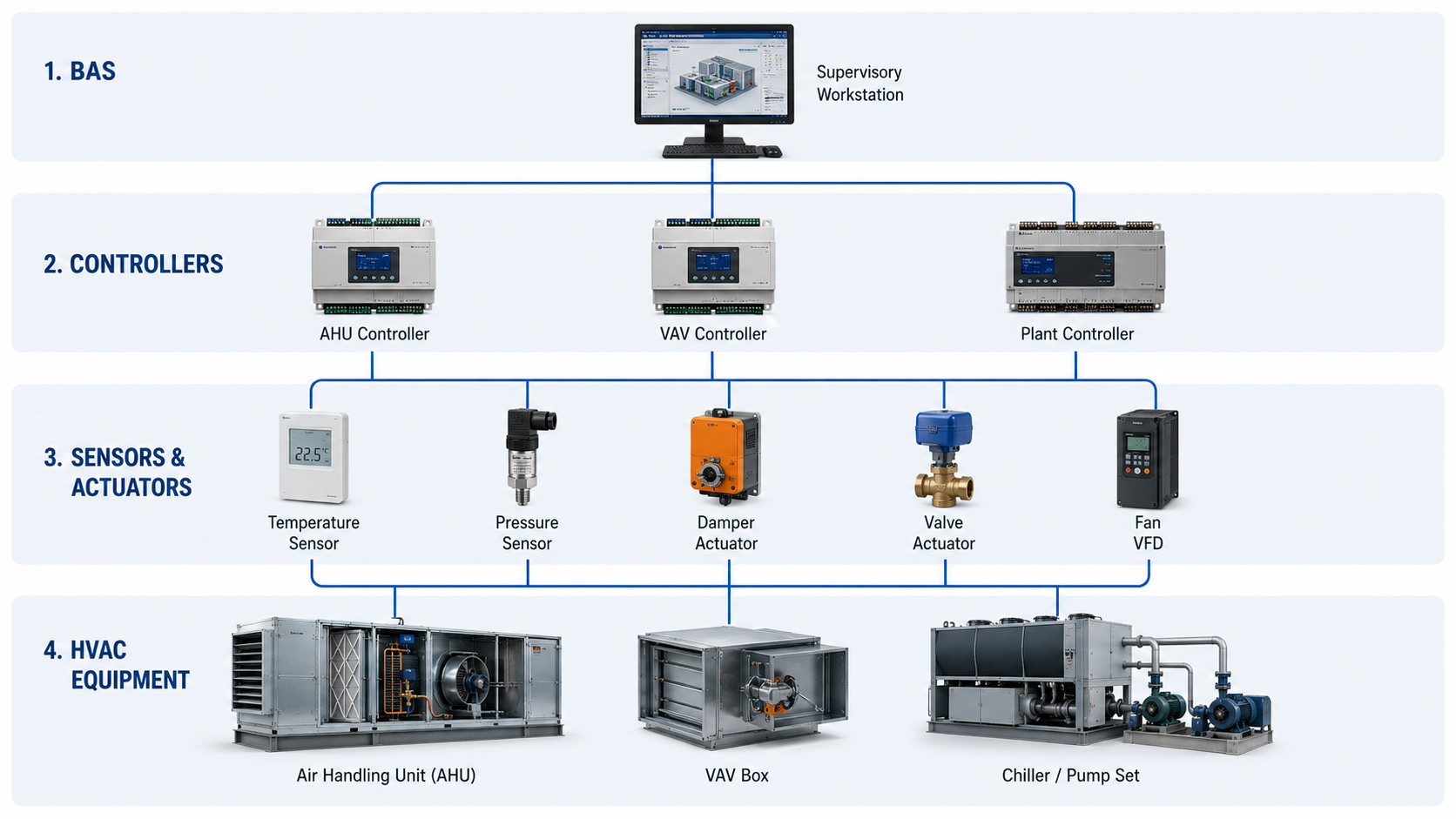
Not every building includes every layer. A packaged rooftop unit may contain most of its control logic internally, while a large central plant may distribute control across equipment controllers, networked supervisory controllers, and operator workstations.
Types of HVAC Controls and Common Terms
HVAC controls can be classified by the signal technology, the location of the logic, or the way multiple devices are connected. Terms such as thermostat, DDC, BAS, BMS, and EMS overlap, but they do not always describe the same scope.
Thermostats and equipment controls
A thermostat measures space temperature and requests heating or cooling. Simple thermostats use on-and-off commands, while communicating thermostats and packaged-equipment controllers may also manage fan speeds, staging, compressor protection, schedules, humidity, or diagnostic information.
Direct digital control
Direct digital control, commonly called DDC, uses a programmable controller to read digital or analog inputs and command outputs according to a sequence of operation. DDC controllers are commonly installed at air handlers, terminal units, mechanical rooms, and central plants.
Building automation systems
A building automation system, or BAS, connects controllers and equipment so operators can view status, change approved setpoints, schedule operation, trend data, receive alarms, and coordinate systems. The term building management system, or BMS, is often used similarly, although some platforms include lighting, electrical metering, access control, or other building functions beyond HVAC.
Energy management systems
An energy management system may use BAS data, meters, analytics, schedules, demand limits, optimization logic, or utility signals to manage energy use. It may be part of the BAS or a separate application connected to it.
DDC describes how control logic is implemented at a controller. BAS describes the connected building-level system. BACnet is a communication protocol, not a complete control sequence or assurance that equipment will operate correctly.
Core Components of an HVAC Control System
A working control system needs more than a thermostat and a relay. Each component must provide accurate information, execute the intended logic, produce a usable output, and confirm the physical response.
Sensors and inputs
Sensors convert physical conditions into signals that a controller can use. Common HVAC inputs include:
- Space, outdoor-air, supply-air, return-air, and water temperature
- Relative humidity and dew point
- Duct, building, filter, and hydronic differential pressure
- Airflow, water flow, and equipment current
- Carbon dioxide or other indoor-air-quality indicators
- Occupancy, smoke, freeze-stat, condensate, and equipment safety contacts
- Fan, pump, compressor, damper, and valve status feedback
Sensor location matters as much as sensor accuracy. A temperature sensor affected by direct sunlight, an unsealed wall opening, stratified air, or nearby equipment can produce a technically valid signal that does not represent the controlled space.
Controllers and sequences
The controller compares inputs with setpoints and executes the sequence of operation. The sequence defines operating modes, start and stop conditions, safeties, setpoint resets, alarms, delays, staging, interlocks, and responses to abnormal conditions.
Outputs and actuators
Controller outputs operate physical devices. Outputs may start a fan, enable a boiler, adjust a variable-frequency drive, stage compressors, energize electric heat, or position a damper or control valve. Modulating outputs allow a device to operate between fully closed and fully open rather than switching only between two states.
Networks and operator interface
Control networks exchange data between controllers, equipment, gateways, and supervisory software. The operator interface presents graphics, setpoints, schedules, alarms, overrides, and trend data. A useful graphic should help an operator understand the system rather than merely display hundreds of unorganized points.
A graphics screen may show that a damper is commanded to 100%, but the linkage may be disconnected or the actuator may be stalled. Reliable control requires either position feedback or confirmation that the expected airflow, pressure, or temperature change actually occurred.
How an HVAC Feedback Control Loop Works
A closed-loop HVAC controller continually uses feedback from the controlled process. The difference between the setpoint and the measured value is called the error. The controller changes its output to reduce that error while avoiding unstable or excessive movement.

For example, if a zone temperature rises above its cooling setpoint, a controller may increase the airflow command to a variable air volume terminal. The damper opens, more cool supply air enters the zone, and the space-temperature sensor reports the resulting change.
Setpoint, process variable, and error
The setpoint is the desired value. The process variable is the measured value. The error is the difference between them. A controller uses the magnitude and behavior of the error to determine its output.
Disturbances and system response
Occupants, solar gain, outdoor weather, open doors, equipment loads, airflow changes, and water-temperature changes act as disturbances. A well-designed loop responds to these changes without excessive overshoot, hunting, long delays, or conflicting commands.
On-Off, Staged, Floating, and Modulating Control
Use this comparison to understand how common control methods change equipment output. The appropriate method depends on the equipment, process response, required stability, available hardware, and sequence of operation.
| Control method | How it operates | Common applications | Main consideration |
|---|---|---|---|
| On-off | Switches the output fully on or fully off around a setpoint and differential. | Compressors, electric heat, small fans, pumps, and simple thermostats | Simple and robust, but the controlled value normally cycles through a range. |
| Staged | Enables additional equipment stages as load increases. | Multistage heating, cooling, boilers, chillers, and packaged equipment | Stage thresholds and time delays should prevent rapid cycling. |
| Floating | Drives an actuator open or closed for timed intervals and stops when no correction is required. | Dampers and valves with three-point or incremental control | Position can drift if travel time, end stops, or synchronization are not handled correctly. |
| Proportional or PID | Modulates output according to the error and, when configured, its accumulated and changing behavior. | Airflow, pressure, temperature, valve, damper, pump, and fan-speed control | Poor tuning can cause hunting, slow recovery, overshoot, or sustained error. |
| Supervisory reset | Changes another controller’s setpoint based on load, demand, outdoor conditions, or zone requests. | Supply-air temperature, duct pressure, water temperature, and central-plant optimization | Reset logic must remain within safe and effective equipment limits. |
More complex control is not automatically better. A stable, understandable sequence that matches the mechanical system is usually more valuable than sophisticated logic that cannot be commissioned, maintained, or diagnosed.
Proportional, integral, and derivative action
Proportional action responds to the current error. Integral action responds to error that persists over time and can remove a steady offset. Derivative action responds to how quickly the error changes, although it is not necessary or desirable in every HVAC loop. Many HVAC applications use proportional-integral control without derivative action.
Do not retune a loop until sensor accuracy, actuator operation, valve or damper sizing, flow availability, and the mechanical process have been checked. Controller tuning cannot correct a stuck actuator, oversized valve, unstable airflow, or incorrect sensor.
Sequences of Operation: How HVAC Equipment Is Coordinated
A sequence of operation is the written description of how the HVAC system should behave in each operating condition. It connects the mechanical design to the control programming and gives the commissioning team a basis for functional testing.
Common operating modes
A complete sequence normally distinguishes the modes that materially change system behavior:
- Occupied: Comfort, ventilation, pressure, and indoor-air-quality requirements are actively maintained.
- Unoccupied: Equipment is generally disabled except for protection, setback, setup, or approved demand-response functions.
- Warm-up or cool-down: The system prepares the building before occupancy, often with different ventilation or temperature logic.
- Economizer: Outdoor air is used for cooling when the required conditions and equipment safeties are satisfied.
- Freeze protection: Fans, dampers, valves, pumps, and heat sources respond to low-temperature risk.
- Smoke or life-safety response: HVAC operation follows the applicable approved smoke-control or shutdown strategy.
- Alarm or failure mode: The system responds to failed sensors, lost communications, abnormal pressure, or unavailable equipment.
Interlocks and proofs
An interlock makes one action dependent on another condition. A heating valve may be allowed to open only when a fan is proven on, or a chiller may be enabled only after required water flow is established. Proof should come from a meaningful feedback point rather than from the command alone.
Setpoint reset strategies
Reset strategies adjust setpoints according to actual demand. An air handler might reduce duct static-pressure setpoint when most terminal dampers are partly closed, or adjust supply-air temperature according to zone cooling requests. Effective reset logic reduces unnecessary fan, pump, heating, or cooling effort while preserving zone performance.
For every operating mode, identify the enabling conditions, commanded outputs, required proofs, time delays, limits, alarms, and fallback behavior. Ambiguous phrases such as “as required” are difficult to program and test.
HVAC Controls Troubleshooting Workflow
HVAC control problems are easiest to diagnose by following the signal path instead of replacing components at random. Start with the complaint, verify the physical condition, and then move from the sensor through the logic and output to the controlled process.

- Define the complaint: Identify the affected zone, equipment, time period, operating mode, and observed symptom. “Too hot” is not enough; determine when, where, and under what conditions it occurs.
- Verify the physical condition: Measure temperature, humidity, airflow, pressure, or equipment state with an appropriate independent instrument when practical.
- Check the input: Compare the BAS value with the independent measurement. Inspect sensor placement, calibration, wiring, scaling, and communication quality.
- Check the setpoint and mode: Confirm occupancy, schedule, overrides, deadbands, lockouts, safeties, and the active heating, cooling, ventilation, or economizer mode.
- Read the sequence: Determine what the controller should command under the verified conditions. Review requests, enable logic, delays, limits, and interlocks.
- Inspect the output command: Confirm that the expected relay, analog signal, network command, speed reference, valve position, or damper position is being issued.
- Verify actuator response: Observe whether the device physically moves or starts. Check linkages, stroke, rotation, end switches, relays, drives, and available power.
- Verify the mechanical process: Confirm that air, water, refrigerant, or heat is actually available. Check fans, pumps, filters, coils, valves, dampers, belts, strainers, and equipment safeties.
- Confirm closed-loop recovery: Trend the input, output, setpoint, mode, and relevant status points long enough to verify that the controlled condition stabilizes.
Example: a warm VAV zone
Assume a zone is warm during occupied hours. An independent thermometer confirms that the space is above setpoint. The zone sensor agrees, the cooling loop is requesting maximum airflow, and the VAV damper command is fully open. If measured airflow remains low, changing the temperature-loop tuning will not solve the problem. The next checks should include damper movement, airflow-sensor accuracy, duct pressure, balancing, restrictions, and upstream air-handler operation.
Trend the controlled variable, setpoint, output, operating mode, and equipment proof together. A single trend point rarely shows whether the controller, actuator, or mechanical system caused the failure.
Common HVAC Control Applications
Control strategies should match the equipment and the building’s operating needs. The following examples show how sensors, setpoints, and actuators work together in common systems.
Air-handling unit controls
An air handling unit may control supply-air temperature, duct pressure, outdoor-air ventilation, economizer dampers, heating and cooling coils, humidity, freeze protection, filter alarms, and fan speed. Because these functions interact, the sequence should define priorities and prevent simultaneous heating and cooling unless a justified application requires it.
Variable air volume controls
A variable air volume system coordinates zone airflow, terminal dampers, reheat valves, supply-air temperature, and central fan pressure. Good system-level control considers the requests of multiple zones instead of maintaining unnecessarily high duct pressure at all times.
Chiller and hydronic controls
A chiller system may include chilled-water temperature control, pump staging, differential-pressure reset, chiller staging, cooling-tower coordination, isolation valves, flow proving, and minimum operating limits. Plant optimization must stay within manufacturer requirements and the mechanical design’s allowable flow and temperature ranges.
Heat pump controls
A heat pump system may control compressor staging or speed, reversing-valve position, fan operation, auxiliary heat, defrost, lockouts, and zone demand. Poor staging or poorly coordinated auxiliary heat can reduce efficiency even when space temperature remains acceptable.
Ventilation and building-pressure controls
Ventilation controls may use schedules, occupancy signals, airflow stations, outdoor-air dampers, exhaust-fan status, or indoor-air-quality measurements. Building-pressure control coordinates supply, return, relief, and exhaust airflow, but pressure sensors and reference locations must represent the intended pressure boundary.
These examples explain typical control relationships, not project-specific sequences. Final controls must reflect the actual equipment, approved design documents, manufacturer requirements, owner criteria, climate, occupancy, and applicable codes and standards.
Common HVAC Control Problems and Failure Modes
Many control complaints originate at the boundary between programming and physical equipment. The screen may appear normal while the process is not responding as intended.
- Biased or poorly located sensor: The controller makes a consistent but incorrect decision because the measured condition does not represent the process.
- Incorrect point scaling: A voltage, current, resistance, pulse, or network value is converted into the wrong engineering value.
- Stuck damper or valve: The command changes, but airflow or water flow does not follow because the actuator, linkage, stem, blade, or power supply has failed.
- Command without proof: The software assumes a fan or pump is running because it was enabled, even though the equipment failed to start.
- Overridden point: A temporary operator override remains active and prevents the normal sequence from regaining control.
- Conflicting loops: Heating and cooling, humidification and dehumidification, or local and supervisory controllers work against each other.
- Excessive deadband or delay: The system responds too slowly or allows uncomfortable drift before taking action.
- Aggressive loop tuning: Valves, dampers, fan speeds, or temperatures repeatedly overshoot and reverse direction.
- Unstable process conditions: Insufficient flow, changing supply conditions, oversized devices, or pressure fluctuations prevent the loop from settling.
- Incomplete sequence: Startup, shutdown, failure, unoccupied, alarm, or changeover behavior was never clearly defined.
- Communication failure: Controllers retain old values, lose supervisory commands, or fall back to an unintended default state.
- Alarm overload: Excessive nuisance alarms condition operators to ignore warnings that require action.
When a zone remains uncomfortable at maximum heating or cooling command, the control loop may already be doing everything it can. Check available airflow, water flow, temperatures, equipment capacity, envelope loads, and balancing before modifying the sequence.
Control-system commissioning
Commissioning verifies that installed sensors, actuators, graphics, alarms, trends, safeties, and sequences perform as intended. Functional testing should create the conditions needed to observe transitions between modes rather than confirming only that individual points appear on a screen.
Useful tests include simulating sensor changes, proving fan and pump status, checking fail positions, testing alarms, verifying setpoint resets, observing equipment staging, confirming safeties, and reviewing trend data after the system operates under realistic loads.
HVAC Controls Engineering References
These sources support the control-loop concepts, building-automation terminology, sequence development, networking, and commissioning principles discussed on this page.
- ASHRAE Handbook: Fundamentals of Control Explains HVAC control fundamentals, control components, sequence development, and the role of commissioning.
- ASHRAE Building Controls Resources Identifies key HVAC control publications and references, including BACnet, building-automation specifications, and high-performance sequences.
- U.S. Department of Energy: About Building Controls Provides an overview of how building controls coordinate equipment, support comfort and indoor-air quality, and manage building operation.
Frequently Asked Questions
HVAC controls include all devices and logic used to regulate HVAC equipment, from a standalone thermostat to a central-plant controller. A building automation system connects and supervises multiple controllers and systems through schedules, graphics, alarms, trends, setpoints, and network communication.
DDC means direct digital control. A programmable digital controller reads inputs, executes a defined sequence, and sends outputs to equipment or actuators. DDC can operate independently at the equipment level while also communicating with a larger building automation system.
The essential parts are a sensor that measures the controlled condition, a controller that compares the measurement with a setpoint, and a controlled device or actuator that changes the process. The resulting condition is measured again to complete the feedback loop.
Hunting can result from aggressive tuning, delayed sensor response, oversized valves or dampers, unstable pressure or flow, actuator problems, conflicting loops, or rapidly changing loads. The physical system should be checked before controller gains are changed.
Verify the complaint physically, compare the sensor value with an independent measurement, confirm the active mode and setpoint, follow the programmed sequence, inspect the output command, verify actuator movement, check the mechanical process, and trend the loop until stable operation is confirmed.
Summary and Next Steps
HVAC controls turn measured building conditions into coordinated equipment actions. Sensors provide information, controllers apply the sequence of operation, actuators change the physical system, and feedback shows whether the intended result occurred.
The most important diagnostic distinction is between a control command and a physical response. Verify the sensor, logic, output, actuator, mechanical process, and resulting feedback before changing programming or replacing components.
Where to go next
-
Air Handling Unit
See how fans, coils, dampers, filters, sensors, and control sequences work together inside an air-handling system.
-
Variable Air Volume System
Learn how zone airflow control, terminal dampers, reheat, duct pressure, and air-handler operation are coordinated.
-
Chiller System
Explore chilled-water equipment, plant components, staging, flow control, and central cooling-system operation.