
Table of Contents
Introduction
The main HVAC system components include controls and sensors, heating and cooling equipment, fans and air handlers, ventilation and filtration devices, ductwork or piping, room air-distribution devices, electrical controls, refrigerant piping, and condensate drainage. The exact components depend on the type of HVAC system installed.
An HVAC system is not simply a furnace and an outdoor air conditioner. It is an interconnected system that senses indoor conditions, produces or transfers heat, moves air or water, controls humidity and ventilation, and distributes conditioned air throughout a building.
Key Takeaways
- Six functional groups: Controls, heating and cooling equipment, air handling, ventilation and air quality, distribution, and support components.
- System type matters: Furnaces, heat pumps, boilers, mini-splits, rooftop units, and chilled-water systems do not use identical components.
- Components operate as a chain: A sensor detects a need, controls activate equipment, air or water is conditioned, and the distribution system serves the building.
- Troubleshoot the system path: Weak airflow, no cooling, leaks, and uneven temperatures can each have several possible causes.
How HVAC Components Work Together
A typical forced-air system follows a repeatable operating sequence. Controls request heating or cooling, equipment changes the air temperature and moisture condition, a blower moves the air, and ducts deliver it to the occupied rooms before it returns to the equipment.
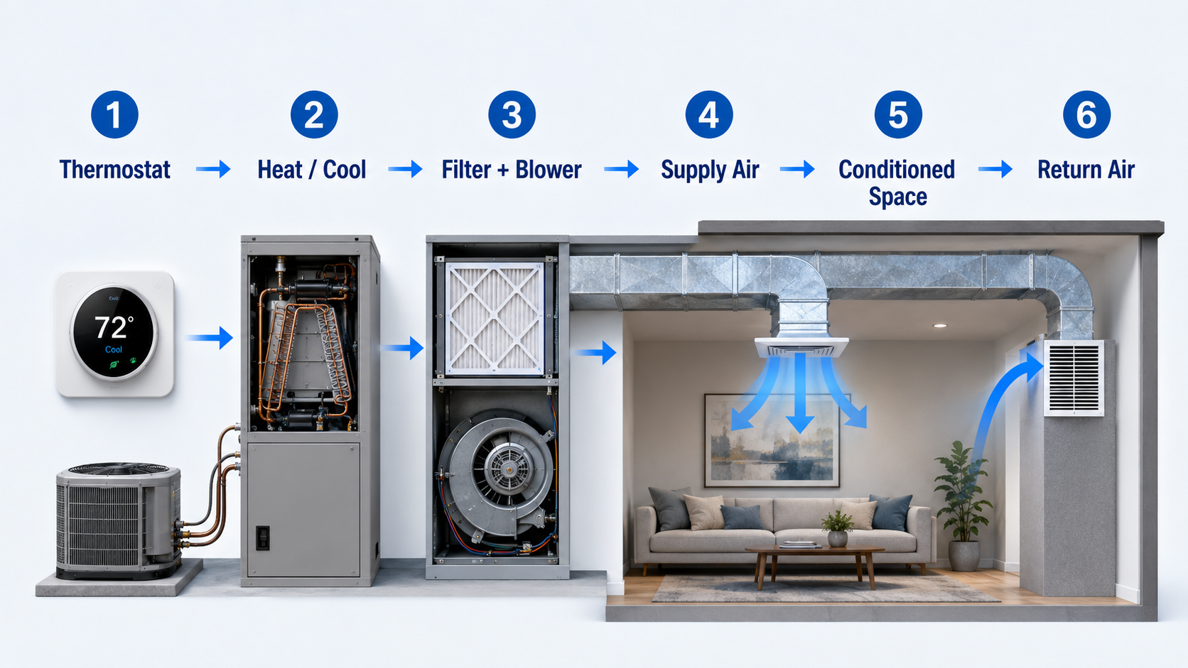
- Sense: A thermostat, temperature sensor, humidity sensor, pressure sensor, or air-quality sensor measures a condition.
- Decide: A controller compares the measured value with a setpoint, schedule, or programmed operating sequence.
- Activate: Relays, contactors, valves, dampers, motors, compressors, burners, heaters, or pumps receive commands.
- Condition: Heating, cooling, filtration, ventilation, humidification, or dehumidification changes the air or water condition.
- Distribute: Fans, ducts, pumps, pipes, terminal units, diffusers, or radiators deliver heating, cooling, or ventilation.
- Return or exhaust: Air returns to the equipment for recirculation or leaves the building through an exhaust system.
A component can operate correctly while the overall system performs poorly. A working blower, for example, cannot overcome a severely restricted filter, dirty coil, closed damper, undersized duct, major duct leak, or incorrect control sequence.
HVAC Components at a Glance
The fastest way to understand an unfamiliar HVAC system is to divide its components by location and function.
Indoor equipment
Indoor components commonly include the furnace or air handler, blower, filter, evaporator coil, heating coil or heat exchanger, control board, drain pan, condensate line, and associated safety devices.
Outdoor equipment
Outdoor components may include the compressor, condenser or heat-pump coil, condenser fan, reversing valve, refrigerant controls, electrical contactors, capacitors, disconnecting means, and protective devices.
Building distribution
Distribution components include supply and return ducts, hydronic piping, pumps, dampers, control valves, registers, grilles, diffusers, terminal units, radiators, and radiant heating or cooling surfaces.
Controls and sensors
Thermostats, sensors, control boards, building automation controllers, relays, contactors, actuators, and safety switches determine when equipment runs and how much heating, cooling, airflow, or water flow it provides.
Follow the connections. Ductwork indicates an air-side function, copper refrigerant tubing indicates a refrigeration function, water piping indicates a hydronic function, drain piping indicates condensate handling, and control wiring indicates sensing or command functions.
The Six Main HVAC Component Groups
HVAC components are easiest to understand when organized by the job they perform. Some components produce heating or cooling, while others control, move, clean, distribute, reject, or drain heat and moisture.
1. Controls and sensors
Controls form the decision layer of the system. A basic residential system may use a wall thermostat and an equipment control board. A commercial system may use many sensors, equipment controllers, networked actuators, and a central building automation system.
- Thermostats: Measure space conditions and provide heating, cooling, fan, or scheduling commands.
- Temperature and humidity sensors: Measure room, outdoor, supply-air, return-air, water, or refrigerant conditions.
- Control boards and controllers: Process inputs and operate equipment according to programmed sequences.
- Actuators: Position dampers and valves to regulate airflow or water flow.
- Relays and contactors: Switch motors, compressors, heaters, and other electrical loads.
- Safety switches: Stop or limit operation when unsafe pressure, temperature, airflow, condensate, combustion, or electrical conditions occur.
2. Heating and cooling equipment
This group adds heat to the building, removes heat from it, or transfers heat between air, refrigerant, water, and the outdoors. Common equipment includes furnaces, heat pumps, air conditioners, boilers, chillers, electric heaters, and heat exchangers.
3. Air-handling equipment
Air-handling components collect, filter, heat, cool, and move air. A residential furnace cabinet may combine a blower, filter rack, heat exchanger, controls, and evaporator-coil connection. A commercial air-handling unit may contain separate fan, coil, filter, mixing, humidification, and damper sections.
4. Ventilation and indoor-air-quality equipment
Ventilation components introduce outdoor air and remove stale or contaminated air. Indoor-air-quality components may filter particles, control moisture, recover energy, or treat specific contaminants.
5. Distribution components
Distribution components carry conditioned air or water to occupied spaces. Forced-air systems use ducts, plenums, dampers, grilles, registers, diffusers, and terminal units. Hydronic systems use pumps, piping, valves, coils, radiators, and other water-side terminal equipment.
6. Support and protection components
Electrical equipment, motors, refrigerant piping, condensate drainage, insulation, equipment supports, vibration isolation, protective devices, and service access allow the primary HVAC equipment to operate safely and reliably.
A compressor is a component. An outdoor condensing unit is an equipment assembly containing several components. A split air-conditioning system includes indoor and outdoor assemblies, controls, refrigerant piping, electrical equipment, drainage, and an air-distribution system.
Controls, Sensors, and Electrical Components
Thermostat and space sensors
The thermostat is the user-facing control in many residential systems. It measures temperature—and sometimes humidity or occupancy—and requests heating, cooling, ventilation, or fan operation. Its signal is sent to an equipment control board or controller rather than directly moving air or refrigerant.
Control board and equipment controller
The controller interprets sensor inputs, applies delays and safety logic, stages equipment, and commands outputs. It may control compressors, burners, heaters, fans, pumps, dampers, valves, defrost cycles, alarms, and equipment shutdowns.
Building automation system
Commercial buildings often connect HVAC controllers to a building automation system. Operators can review temperatures, humidity, pressure, schedules, alarms, equipment status, energy use, and control sequences from a central interface.
Relays, contactors, and transformers
- Relays: Use one electrical signal to switch another circuit.
- Contactors: Switch larger electrical loads such as compressors, heaters, and motors.
- Transformers: Provide the lower control voltage used by many thermostats, control boards, relays, and actuators.
Motors, capacitors, and variable-frequency drives
Motors drive blowers, fans, pumps, and compressors. Some single-phase motors use capacitors for starting or running. Variable-frequency drives regulate motor speed in compatible systems, allowing airflow or water flow to respond to changing demand.
Safety controls
Safety devices may include high- and low-pressure switches, temperature limits, flame sensors, rollout switches, airflow switches, freeze protection, motor overloads, float switches, smoke-control interlocks, and equipment disconnects.
A safety switch usually opens because the system has detected an unsafe or abnormal condition. Repeatedly resetting or bypassing the device can damage equipment or create a serious hazard.
Heating Components and What They Do
Furnace components
A furnace heats air before a blower distributes it through ductwork. Depending on the energy source and equipment design, a furnace may contain the following components:
- Burner or electric heating element: Produces heat from fuel combustion or electrical resistance.
- Heat exchanger: Transfers heat to the airstream while keeping combustion products separate from supply air in a combustion furnace.
- Ignition system: Initiates combustion in applicable gas-fired equipment.
- Gas valve: Regulates fuel flow when heating is requested.
- Induced-draft fan: Moves combustion gases through the heat exchanger and vent system in applicable furnaces.
- Flame sensor: Confirms that flame is present when fuel is being supplied.
- Limit and rollout switches: Stop or limit operation when unsafe temperatures or combustion conditions occur.
- Blower: Moves return air across the heat exchanger and into the supply ducts.
Heat-pump heating components
A heat pump transfers heat rather than producing all of its heat through combustion or electrical resistance. In heating mode, the outdoor coil absorbs heat and the indoor coil releases it. A reversing valve changes refrigerant flow so the indoor and outdoor coils exchange roles between heating and cooling modes.
Many air-source heat-pump systems also include auxiliary electric heat. Auxiliary heat can supplement the refrigeration cycle during high heating demand, defrost operation, or certain equipment conditions.
Boiler and hydronic heating components
A boiler heats water or produces steam for delivery to coils, radiators, baseboard units, radiant surfaces, or process loads. A hydronic system commonly includes:
- Boiler or another water-heating source
- Circulation pumps
- Supply and return piping
- Control and balancing valves
- Expansion tank
- Air separator and vents
- Heat exchangers or terminal heating units
- Temperature, pressure, and flow controls
Combustion, fuel, flue, pressurized-water, line-voltage, and safety-control work should follow equipment documentation and applicable requirements. Do not bypass a limit switch, pressure switch, flame safeguard, or other protective device.
Cooling and Refrigeration Components
Most conventional air conditioners and heat pumps use a vapor-compression refrigeration cycle. Four core components move refrigerant through a closed loop and transfer heat from one location to another.

Evaporator coil
The evaporator is the heat-absorbing side of the cooling cycle. Warm air passes across the cold coil, transferring heat to the refrigerant. Moisture may also condense on the coil when its surface is colder than the air’s dew-point temperature.
Compressor
The compressor circulates refrigerant and raises the pressure and temperature of refrigerant vapor. It is commonly located in an outdoor condensing unit, packaged unit, rooftop unit, chiller, or heat-pump assembly.
Condenser coil
The condenser rejects heat from the refrigerant. In a typical air-cooled system, an outdoor fan moves ambient air across the condenser coil. Water-cooled equipment transfers heat to a water loop that may ultimately reject heat through a cooling tower or another heat sink.
Expansion device
The expansion device meters refrigerant into the evaporator and creates the pressure reduction needed for low-temperature heat absorption. Common devices include thermostatic expansion valves, electronic expansion valves, and fixed metering devices.
Refrigerant lines and accessories
Refrigerant piping connects the cycle components. Depending on the system, additional components may include a reversing valve, accumulator, receiver, filter-drier, oil-management devices, pressure sensors, service valves, and refrigerant controls.
The evaporator, compressor, condenser, and expansion device are the four core refrigeration-cycle components. They are not the complete HVAC system; controls, fans, filters, ducts, ventilation, electrical equipment, and drainage are still required.
Air-Handling, Ventilation, and Air-Quality Components
Air handler
An air handler is an equipment assembly that moves and conditions air. It may contain a supply fan or blower, heating and cooling coils, filters, dampers, access sections, drain pans, sensors, and controls. A furnace can perform air-handling functions, but a furnace and an air handler are not always the same equipment type.
Blowers and fans
Fans create the pressure difference required to move air through filters, coils, ducts, dampers, terminal devices, and rooms.
- Supply fan: Moves conditioned air toward occupied spaces.
- Return fan: Assists the return-air path in larger systems.
- Exhaust fan: Removes air from toilets, kitchens, laboratories, process areas, and other exhaust zones.
- Outdoor condenser fan: Moves outdoor air across an air-cooled condenser coil.
- Induced-draft fan: Supports combustion-gas movement in applicable heating equipment.
Filters and air cleaners
Filters protect HVAC equipment and reduce airborne particles. The appropriate filter depends on equipment capability, air-quality goals, pressure-drop limits, and maintenance practices. A filter that is too restrictive for the available fan pressure can reduce airflow even when it is clean.
Filter efficiency is commonly described using a MERV rating. A higher rating can improve particle capture, but the filter must remain compatible with the system’s airflow and available static pressure.
Outdoor-air and exhaust components
Ventilation systems may use outdoor-air intakes, louvers, dampers, mixing boxes, makeup-air units, exhaust fans, heat-recovery ventilators, or energy-recovery ventilators. These components manage the controlled exchange of indoor and outdoor air.
Humidity-control components
Cooling coils remove moisture when water condenses on their surfaces. Dedicated dehumidifiers can provide additional moisture removal, while humidifiers add moisture where low indoor humidity is a concern. Humidity control depends on equipment capacity, airflow, operating time, controls, outdoor-air load, and building moisture sources.
The psychrometric chart helps engineers evaluate the combined effects of temperature, humidity, cooling, heating, humidification, and dehumidification.
Drain pan, trap, and condensate piping
Water removed at a cooling coil collects in a drain pan and leaves through a condensate drain. The system may require a trap, vent arrangement, float switch, or condensate pump depending on equipment pressure and drainage conditions. A blocked or incorrectly configured drain can cause leaks, equipment shutdown, microbial growth, or building damage.
Air and Water Distribution Components
Supply and return ducts
Supply ducts carry conditioned air from the equipment to the rooms. Return ducts carry air back to the equipment. Both paths affect airflow, fan pressure, noise, filtration, comfort, and equipment performance.
- Supply plenum: Connects the equipment outlet to the main supply duct system.
- Return plenum: Collects return air before it enters the equipment.
- Trunk ducts: Carry larger portions of system airflow.
- Branch ducts: Deliver air to individual zones, rooms, or outlets.
- Balancing dampers: Adjust airflow through branches.
- Zone dampers: Modulate airflow in response to zoning controls.
- Flexible connectors: Reduce vibration transmission between equipment and ductwork where appropriately applied.
Grilles, registers, and diffusers
- Grille: A covering or air opening that generally does not include an integral volume-control damper.
- Register: A grille-type outlet with an adjustable damper.
- Diffuser: A supply-air device designed to distribute air in a controlled pattern.
Terminal units
Commercial systems may use variable-air-volume boxes, fan-powered terminal units, reheat coils, induction units, fan-coil units, or other devices to regulate airflow and temperature near the served zones.
Hydronic distribution
Hydronic systems move heated or chilled water through pumps, piping, valves, and coils. A complete loop may include primary and secondary pumps, balancing valves, control valves, strainers, expansion tanks, air separators, heat exchangers, temperature sensors, pressure sensors, and flow-measurement devices.
Equipment capacity does not guarantee room comfort. The distribution system must deliver the required airflow or water flow at an acceptable pressure drop. Review duct sizing and HVAC air balancing for more detail.
Which Components Does Each HVAC System Use?
Use this comparison to see which component groups are normally present in common systems. Actual equipment arrangements vary by manufacturer, climate, building size, project requirements, and design approach.
| HVAC system | Heating and cooling equipment | Distribution | Defining components |
|---|---|---|---|
| Furnace with split air conditioner | Furnace, indoor evaporator coil, and outdoor condensing unit | Supply and return ducts | Burner or heater, heat exchanger, blower, compressor, condenser, and expansion device |
| Split heat pump | Indoor coil or air handler and outdoor heat-pump unit | Supply and return ducts | Reversing valve, compressor, indoor and outdoor coils, expansion controls, and optional auxiliary heat |
| Packaged or rooftop unit | Heating, cooling, fans, filters, and controls combined in one cabinet | Ductwork connected to the packaged unit | Packaged burners or heaters, coils, compressor, fans, and outdoor-air or economizer section where provided |
| Ductless mini-split | Outdoor heat-pump or condensing unit with one or more indoor units | Refrigerant piping without a central supply-and-return duct system | Indoor fan-coil units, outdoor unit, individual controls, refrigerant lines, and condensate drains |
| Boiler or hydronic heating | Boiler or central heating source | Pumps and water piping | Expansion tank, valves, air separator, radiators, baseboards, radiant surfaces, or heating coils |
| Chilled-water system | Chiller, air handlers or terminal coils, and heat-rejection equipment as required | Chilled-water piping plus an air-distribution system | Chilled-water pumps, control valves, coils, and cooling tower or condenser-water equipment where applicable |
A system name often describes its primary equipment or distribution method rather than every installed component. A heat-pump system, for example, still requires controls, electrical power, refrigerant piping, air movement, drainage, and a way to deliver heating and cooling to the rooms.
For a broader comparison of complete configurations, see Types of HVAC Systems.
HVAC Component Finder: Identify a Part by Its Function
Start with the job the unknown component performs. Then check its location, the medium it handles, and the components connected before and after it.
What controls the system?
Look for a thermostat, sensor, control board, equipment controller, building automation controller, relay, contactor, valve actuator, or damper actuator. Trace control wiring or network connections rather than airflow piping.
What creates or delivers heat?
Look for a burner, electric heating element, furnace heat exchanger, boiler, heat-pump coil, hot-water coil, radiator, baseboard unit, or radiant terminal. Identify whether the energy source is fuel, electricity, refrigerant, hot water, or steam.
What removes heat from indoor air?
Look for an evaporator coil, chilled-water coil, ductless indoor coil, or another cooling heat exchanger. Follow the connected refrigerant lines or hydronic piping to locate the remaining cooling equipment.
What moves air?
Look for a blower, supply fan, return fan, exhaust fan, condenser fan, or terminal-unit fan. Identify the fan inlet, outlet, motor, casing, and connected duct path.
What cleans or treats air?
Look for filters, air cleaners, humidifiers, dehumidifiers, ultraviolet devices, outdoor-air components, or energy-recovery equipment. Confirm the component’s intended purpose and installation requirements from its documentation.
What changes airflow or water flow?
Air systems use dampers, fan-speed controls, inlet devices, and terminal units. Hydronic systems use control valves, balancing valves, pump-speed controls, and bypass arrangements.
What rejects heat outdoors?
Look for an air-cooled condenser, outdoor heat-pump coil, cooling tower, fluid cooler, or another heat-rejection device. Do not assume every outdoor cabinet is only a condenser; a heat pump changes coil function by operating mode.
What handles condensate?
Look for a drain pan beneath a cooling coil, condensate outlet, trap, drain line, float switch, or condensate pump. Water near equipment may also come from piping, humidification equipment, roof drainage, or another building source.
By identifying the component’s function, location, connections, and operating medium, you can usually determine its component group before searching for the exact equipment model or replacement part.
HVAC Troubleshooting by Component Group
Begin with the observed symptom and inspect the component groups that could create it. The visual below identifies useful starting points, not guaranteed diagnoses.

No airflow or weak airflow
- Confirm the thermostat mode and fan command.
- Inspect the filter for blockage or incorrect installation.
- Check accessible supply and return grilles for obstruction.
- Verify that accessible dampers are not closed.
- Consider blower, motor, control, coil-fouling, duct-leakage, or duct-restriction problems.
System runs but does not cool
- Confirm the cooling setpoint and operating mode.
- Check whether both indoor and outdoor equipment are operating.
- Inspect airflow conditions before assuming a refrigerant problem.
- Look for dirty coils, blocked outdoor airflow, control problems, or equipment shutdowns.
- Use qualified service for refrigerant, compressor, capacitor, contactor, and line-voltage diagnosis.
Water near indoor equipment
- Inspect the drain pan and visible condensate line.
- Look for a blocked drain, failed condensate pump, damaged pan, or activated float switch.
- Consider coil icing caused by airflow, controls, equipment, or refrigeration problems.
- Protect the surrounding building area before restarting equipment.
Uneven room temperatures
- Check supply outlets, return paths, doors, and accessible dampers.
- Compare airflow among rooms rather than judging temperature alone.
- Inspect duct leakage, duct size, branch routing, balancing, zoning controls, and room thermal loads.
- Determine whether the problem occurs continuously or only during peak heating or cooling conditions.
Short cycling
Repeated rapid starts and stops may involve thermostat location, controls, restricted airflow, dirty coils, safety-limit operation, condensate switches, incorrect equipment sizing, or equipment-specific faults. Avoid repeatedly resetting equipment that is stopping on a safety control.
Unusual noise or vibration
Rattling, grinding, squealing, buzzing, or severe vibration may involve loose panels, fan wheels, bearings, motors, compressors, contactors, duct movement, refrigerant flow, or mounting problems. Shut down equipment when the noise suggests mechanical damage or an electrical fault.
Stop using the equipment when there is a fuel odor, combustion concern, smoke, arcing, damaged wiring, repeated breaker operation, severe vibration, major refrigerant-line damage, rapidly spreading water, or repeated safety shutdown.
HVAC Component Maintenance Priorities
Maintenance should preserve airflow, heat transfer, drainage, control accuracy, and safe operation. The correct procedure and service interval depend on the equipment and operating environment.
Basic checks building occupants can make
- Review the thermostat mode, schedule, and setpoint.
- Inspect or replace accessible filters according to the equipment and filter instructions.
- Keep supply and return grilles unobstructed.
- Keep leaves, debris, storage, and vegetation away from outdoor equipment.
- Watch for water around indoor equipment or a condensate pump.
- Listen for changes in noise, vibration, cycling, or airflow.
Professional maintenance and commissioning checks
- Measure airflow and external static pressure.
- Inspect and clean coils, fans, burners, heat exchangers, and drain systems as applicable.
- Test electrical connections, current draw, capacitors, contactors, motors, and safeties.
- Verify refrigerant-system and hydronic-system operation using equipment-specific procedures.
- Check combustion, venting, flame safeguards, and fuel components where applicable.
- Verify sensors, controls, staging, dampers, valves, alarms, and operating sequences.
- Confirm that equipment remains accessible for inspection and replacement.
Maintenance frequency should respond to actual conditions. A filter in a construction environment, a coil handling high outdoor-air loads, or a drain serving long cooling seasons may require more frequent attention than the same component in a cleaner or lighter-duty application.
HVAC Component Compatibility and Design Review
Correct individual components can still form a poor system when capacities, pressure drops, controls, materials, or operating sequences are incompatible. Use this checklist during design review, replacement planning, or system troubleshooting.
- Confirm the load: Determine the heating, sensible-cooling, latent-cooling, and ventilation requirements before selecting equipment. Start with the HVAC load calculation guide.
- Match equipment capacity: Confirm that coils, compressors, heat sources, fans, pumps, and terminal units can satisfy the design condition without relying on incompatible assumptions.
- Check airflow and water flow: Verify design flow rates, coil requirements, fan or pump capability, balancing provisions, and expected operating ranges.
- Account for pressure drop: Include filters, coils, dampers, ducts, fittings, terminal devices, piping, valves, strainers, and heat exchangers.
- Verify electrical compatibility: Check voltage, phase, frequency, circuit requirements, motor controls, disconnects, transformer capacity, and control voltage.
- Verify control compatibility: Confirm sensor types, signal ranges, thermostat stages, controller outputs, actuator actions, safeties, interlocks, alarms, and failure modes.
- Confirm refrigerant or water-side compatibility: Follow equipment documentation for refrigerant, piping, oil management, water quality, freeze protection, flow, and pressure requirements.
- Plan condensate management: Provide drainage, traps, pumps, overflow protection, insulation, slope, and maintenance access as required by the equipment arrangement.
- Check service clearances: Filters, coils, fans, motors, valves, controls, pans, and heat exchangers need space for inspection, cleaning, removal, and replacement.
- Commission the complete system: Verify operating sequences, airflow, temperatures, pressures, control responses, safety devices, drainage, and zone performance under actual operating conditions.
Practical component review example
Consider a replacement air handler with a higher-efficiency filter and a new cooling coil. Each item may be correctly selected on its own, but the combined filter and coil pressure drop could exceed the available fan pressure. The result may be reduced airflow, inadequate capacity, poor dehumidification, excessive noise, or coil icing.
The review must therefore include the complete air path: return grille, return duct, filter, coil, fan, supply duct, fittings, dampers, and room outlets—not only the nominal capacity printed on the equipment.
Many HVAC problems occur at the connections between components: an abrupt duct transition, incorrectly trapped drain, mismatched control signal, inaccessible filter, closed balancing damper, unsupported refrigerant line, or valve installed against its required flow direction.
HVAC Systems and Equipment References
These references support the system classifications, component groups, and heating-and-cooling principles used throughout this page.
- ASHRAE Handbook—HVAC Systems and Equipment Organizes HVAC systems and equipment across air handling, heating, cooling, distribution, controls, motors, pumps, valves, and heat exchangers.
- ASHRAE Fundamentals of HVAC Systems Supports the system-level relationship among heating, cooling, ventilation, air movement, and conditioned spaces.
- U.S. Department of Energy Heating and Cooling Resources Provides general heating, cooling, energy-transfer, building-comfort, and system-efficiency context.
Frequently Asked Questions
A typical forced-air residential system includes a thermostat, furnace or air handler, blower, filter, heating equipment, evaporator coil, outdoor condensing or heat-pump unit, refrigerant lines, supply and return ducts, grilles or registers, electrical controls, and condensate drainage.
Not necessarily. Both can contain a blower and other air-side components, but a furnace includes a heating section such as a combustion heat exchanger or electric heater. An air handler may instead work with a heat pump, chilled-water coil, hot-water coil, or another external heating and cooling source.
The four core vapor-compression refrigeration components are the evaporator, compressor, condenser, and expansion or metering device. Together they circulate refrigerant through a loop that absorbs heat at one location and rejects it at another.
An outdoor unit commonly contains a compressor, condenser or heat-pump coil, fan, electrical controls, and protective devices. Packaged and rooftop systems may place most heating, cooling, ventilation, and air-handling components outdoors in one cabinet.
Weak airflow can result from a restricted filter, dirty coil, blower or motor problem, closed damper, blocked grille, leaking or undersized duct, excessive pressure drop, or incorrect control setting. The symptom does not identify one failed component by itself.
Summary and Next Steps
HVAC system components form a connected chain: sensors measure conditions, controls make decisions, heating or cooling equipment transfers energy, fans or pumps move air or water, and distribution components serve the occupied spaces. Ventilation, filtration, electrical protection, drainage, and safety devices support that process.
When selecting or troubleshooting equipment, follow the complete system path. Verify capacity, flow, pressure drop, controls, electrical requirements, drainage, service access, and component compatibility rather than judging one part in isolation.
Where to go next
-
Compare the types of HVAC systems
See how these components are assembled into split, packaged, ductless, hydronic, and central systems.
-
Learn HVAC load calculation
Understand how building loads determine heating and cooling equipment requirements.
-
Use the HVAC load calculator
Estimate preliminary heating, cooling, and equipment-capacity requirements.