
Table of Contents
Introduction
HVAC static pressure is the resistance a blower must overcome to move air through filters, coils, ducts, fittings, grilles, and registers. It is usually measured in inches of water column. High static pressure generally indicates excessive airflow resistance, but the result must be compared with the equipment manufacturer’s rated total external static pressure.
Static pressure is not the same as airflow. A pressure test shows how much resistance the blower encounters, while blower data or an airflow measurement is still needed to determine how much air the system actually delivers.
Key Takeaways
- Core idea: Static pressure represents resistance to airflow within the equipment and duct system.
- Main calculation: Total external static pressure equals the magnitude of the return reading plus the supply reading.
- Best diagnostic clue: Comparing return and supply pressure helps identify which side of the system deserves further testing.
- Critical limitation: A static-pressure reading does not prove airflow without equipment-specific blower data or an airflow test.
How Static Pressure Changes Through an HVAC System
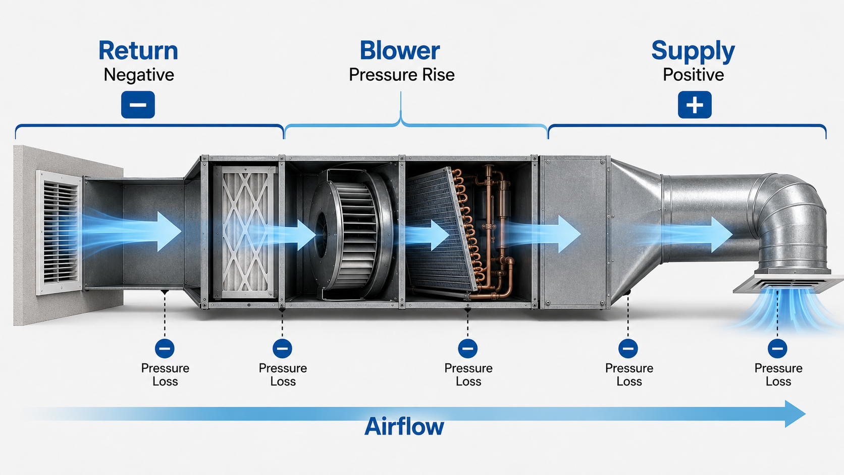
Think of the blower’s available pressure as a limited budget. Every component and duct section uses part of that budget, leaving less pressure available for the rest of the airflow path.
What HVAC Static Pressure Means
Static pressure is the pressure exerted against the interior surfaces of HVAC equipment and ductwork. Field measurements are normally referenced to the pressure in the surrounding room or mechanical space, which the manometer treats as the zero-pressure reference.
On a typical draw-through residential system, the blower pulls air through the return path, producing negative pressure upstream of the blower. The blower then adds energy to the air, producing positive pressure on the supply side.
Positive and Negative Static Pressure
- Negative return pressure: The pressure inside the return duct is lower than the surrounding room pressure.
- Blower pressure rise: The blower increases the air pressure as air passes through the fan section.
- Positive supply pressure: The pressure downstream of the blower is higher than the surrounding room pressure.
- Pressure losses: Filters, coils, duct walls, fittings, dampers, grilles, and registers reduce the available pressure.
Static Pressure Versus Airflow
Static pressure and airflow interact through the blower’s operating curve, but they are not interchangeable measurements. When system resistance changes, the blower moves to a different operating point. The resulting airflow depends on the fan, motor, speed setting, controls, and equipment configuration.
- Static pressure describes pressure acting against the duct or equipment surfaces.
- Velocity pressure represents the kinetic energy associated with air velocity.
- Total pressure is the sum of static pressure and velocity pressure at a location.
- Airflow is the volume of air delivered over time, commonly expressed in cubic feet per minute, or CFM.
High static pressure does not mean the system is delivering strong airflow. It usually means the blower is working against substantial resistance, and actual airflow may be lower than required.
Static Pressure Units
HVAC field measurements in the United States commonly use inches of water column, written as in. w.c., in. wg, or inH₂O. SI calculations commonly use pascals.
These air-pressure values are much smaller than typical refrigerant or hydronic-system pressures. Technicians therefore use sensitive manometers rather than ordinary mechanical pressure gauges.
Total External Static Pressure Explained
Total external static pressure, abbreviated TESP, represents the pressure difference experienced by the air-moving equipment between its applicable external inlet and outlet boundaries.
The return reading is normally negative and the supply reading positive. Calculate TESP by adding their magnitudes rather than allowing the signs to cancel.
- \(\mathrm{TESP}\) Total external static pressure, usually measured in inches of water column or pascals.
- \(P_{\mathrm{return}}\) Static pressure at the applicable external return-side test location, normally negative relative to the room.
- \(P_{\mathrm{supply}}\) Static pressure at the applicable external supply-side test location, normally positive relative to the room.
Worked TESP Example
Assume an HVAC system has a return static-pressure reading of \(-0.32\) in. w.c. and a supply reading of \(+0.27\) in. w.c.
The measured TESP is 0.59 in. w.c. Whether that result is acceptable depends on the equipment’s rated external static pressure, active blower setting, required airflow, and manufacturer fan-performance data.
What “External” Includes
The word external is important because equipment arrangements differ. A furnace with an evaporator coil installed above the cabinet may use different test boundaries than an air handler with an internal coil. Filters may also be internal, cabinet-mounted, or remotely located at a return grille.
Before choosing test locations, identify:
- The exact furnace, fan coil, air handler, or packaged-unit model.
- The manufacturer’s rated maximum external static pressure.
- Whether the filter and evaporator coil are included within the rated cabinet.
- The active blower speed, airflow setting, or operating stage.
- The applicable blower-performance table or fan curve.
A probe installed on the wrong side of a filter or coil can include or exclude resistance that the equipment rating treats differently. Match the measurement locations to the manufacturer’s defined external boundary.
How to Measure HVAC Static Pressure
A typical TESP test uses a dual-port digital manometer, pressure tubing, and static-pressure probes. The equipment should operate under a documented test condition, commonly the highest required airflow mode unless the manufacturer or commissioning procedure specifies otherwise.

- Identify the equipment: Record the model, rated external static pressure, blower setting, filter arrangement, and coil location.
- Inspect the system: Look for unsafe access, missing panels, severe filter loading, damaged ductwork, or other conditions that could affect the test.
- Prepare the instrument: Connect the appropriate static-pressure probes and tubing, then zero the manometer according to its instructions.
- Establish the test condition: Run the blower at the required heating, cooling, or commissioning airflow and allow operation to stabilize.
- Measure return pressure: Place the return probe at the correct external inlet boundary and record the negative reading.
- Measure supply pressure: Place the supply probe at the correct external outlet boundary and record the positive reading.
- Calculate TESP: Add the absolute values of the return and supply readings.
- Compare with equipment data: Review the rated pressure and manufacturer blower table at the actual fan setting.
- Seal the test ports: Remove the probes and close the openings using an appropriate permanent sealing method.
Use a Static-Pressure Probe
A static-pressure probe is designed to sense pressure acting against the duct walls while reducing the effect of air velocity. A pitot tube measures total and static pressure for velocity calculations and should not be confused with a simple static-pressure tip.
Choose Stable Test Locations
Avoid placing probes directly in highly turbulent airflow when a more representative location is available. Abrupt fittings, blower discharge regions, turning vanes, and other disturbances can produce unstable or misleading readings.
Common Measurement Errors
- Failing to zero the manometer before testing.
- Using the wrong probe or tubing connection.
- Testing with equipment panels removed when the system normally operates closed.
- Taking readings at undocumented or incorrect equipment boundaries.
- Testing at an unknown blower speed or operating stage.
- Taking measurements in highly turbulent airflow.
- Comparing the result with a generic target instead of manufacturer data.
- Treating the TESP reading as a direct airflow measurement.
Testing may involve electrical components, rotating equipment, sharp sheet metal, hot surfaces, and combustion equipment. Follow manufacturer instructions and applicable safety procedures. Unqualified users should not drill test ports or open equipment compartments.
What Is a Good HVAC Static Pressure?
A good HVAC static-pressure result is one that remains within the air-moving equipment manufacturer’s rated external static pressure while the system delivers the required airflow.
Approximately 0.50 in. w.c. is frequently discussed as a residential reference value, but it is not a universal target. Equipment ratings, blower types, cabinet arrangements, filters, coils, and required airflow vary.
Compare With the Equipment Rating
Begin by comparing measured TESP with the equipment’s rated maximum external static pressure.
If equipment rated for 0.50 in. w.c. is measured at 0.65 in. w.c., it is operating at 130% of the rated pressure:
This comparison identifies a pressure concern, but it does not identify the cause. Return pressure, supply pressure, component pressure drops, blower data, and actual airflow are needed to complete the diagnosis.
How Blower Type Affects the Result
Blower response depends on the motor, controls, fan geometry, and operating mode:
- Conventional fixed-speed systems: Delivered airflow generally decreases as external resistance rises.
- Constant-torque systems: The motor may compensate for some resistance, but airflow can still decline as the system moves outside its intended range.
- Constant-airflow variable-speed systems: The controls may increase blower speed and power to maintain airflow until the motor or fan reaches an operating limit.
A variable-speed blower that temporarily maintains airflow does not make restrictive ductwork acceptable. Higher speed can increase noise, electrical consumption, and motor loading while leaving the underlying restriction unresolved.
Evaluate pressure and airflow together. Pressure indicates system resistance; airflow indicates whether the equipment is delivering the air required for heating, cooling, dehumidification, and comfort.
HVAC Static Pressure Diagnostic Matrix
Use this matrix after confirming the test condition, instrument setup, probe locations, and equipment rating. The goal is to select the next useful measurement—not to diagnose the entire system from one pressure value.
| Reading pattern | Likely interpretation | What to check next | Important limitation |
|---|---|---|---|
| TESP is within the equipment rating and airflow is correct | The total equipment and duct resistance may be acceptable at the tested operating condition. | Confirm room delivery, temperature performance, noise, and system balance. | An acceptable total reading can still hide branch restrictions, leakage, or poor room distribution. |
| TESP exceeds the equipment rating | The system has excessive resistance, an excessive airflow command, or both. | Compare return and supply pressure, then isolate individual component pressure drops. | TESP alone does not identify the restricted component. |
| Return pressure magnitude is dominant | The return side contributes a larger portion of the measured resistance. | Check the filter, filter cabinet, return grille, return duct, flex duct, and transition. | The supply side and internal components can still contribute meaningful resistance. |
| Supply pressure is dominant | The supply side contributes a larger portion of the measured resistance. | Check the coil, plenum, fittings, dampers, branches, boots, and registers. | The expected pressure split varies with the actual equipment and duct layout. |
| High pressure drop across the filter | The filter, filter area, filter cabinet, or loading condition may be restrictive. | Compare filter pressure drop with applicable product or system data. | MERV rating alone does not determine installed pressure drop. |
| High pressure drop across the coil | The coil may be dirty, wet, incorrectly selected, damaged, or carrying excessive airflow. | Inspect the coil and compare its pressure drop with manufacturer data when available. | Coil pressure drop changes with airflow and operating condition. |
| Low TESP with low airflow | The blower may be running slowly, duct leakage may be present, or the measurement may be incomplete. | Verify blower setup, test locations, duct integrity, and airflow directly. | Low static pressure does not prove that the duct system is properly designed. |
| Acceptable TESP but poor airflow in one room | The problem is likely localized to a branch, damper, register, leakage point, or balancing condition. | Inspect and measure the affected branch and outlet. | Whole-system TESP cannot evaluate every branch independently. |
The most useful diagnostic measurement is often the one that divides the system into smaller sections. Start with return versus supply, then test individual filters, coils, accessories, or duct sections.
Common Causes of High HVAC Static Pressure
High static pressure develops when the blower must overcome more resistance than the equipment and air-distribution system were intended to handle. Restrictions may occur on the return side, within the equipment, on the supply side, or at several locations simultaneously.
Return-Side Restrictions
- Loaded filter: Dust accumulation reduces available flow area and increases pressure drop.
- Insufficient filter area: A small filter face area can create excessive velocity and resistance even when the filter is clean.
- Restrictive filter cabinet: Narrow openings, poor transitions, or internal obstructions can increase resistance.
- Undersized return duct: A return path that is too small for the required airflow can create high velocity, noise, and pressure loss.
- Restrictive return grille: Small free area, dense grille construction, or blocked furniture can limit airflow.
- Compressed flex duct: Crushing, sagging, sharp bends, or excess length can create substantial resistance.
- Poor return transition: Abrupt or misaligned connections can create turbulence and local pressure loss.
Equipment and Component Restrictions
- Dirty evaporator coil: Debris on the entering-air surface restricts airflow through the coil fins.
- High coil pressure drop: Even a clean coil can be restrictive at an airflow outside its intended operating range.
- Dirty blower wheel: Accumulation on the blades can reduce fan performance and alter the operating point.
- Restrictive accessories: Humidifiers, zoning components, specialty filters, and poorly installed add-on devices consume available pressure.
- Incorrect airflow setting: A blower commanded to move more air than the duct system can support may create excessive static pressure.
Supply-Side Restrictions
- Undersized supply duct: Small trunks and branches increase air velocity and friction.
- Closed balancing dampers: Restricting the available flow area increases resistance.
- Closed supply registers: Closing outlets can raise system pressure and disrupt room-to-room balance.
- Restrictive fittings: Sharp elbows, poor takeoffs, abrupt transitions, and crowded plenums consume pressure.
- Compressed supply flex duct: Sagging, crushing, and tight bends increase resistance.
- Long effective length: Numerous fittings can make a short physical duct route behave like a much longer airflow path.
Several moderate restrictions can combine to create one high TESP reading. Correcting only the most visible issue may improve performance without bringing pressure and airflow into an acceptable range.
How to Troubleshoot High HVAC Static Pressure
Start with the total reading, divide the system into return and supply sides, and then isolate individual component pressure drops. This sequence reduces guesswork and helps prevent unnecessary equipment or duct replacement.

- Verify the test: Confirm the manometer is zeroed, the probes are appropriate, and the test locations match the equipment boundary.
- Confirm operating conditions: Record the fan speed, airflow setting, operating stage, filter condition, and panel configuration.
- Calculate TESP: Add the magnitudes of the return and supply readings.
- Compare with the equipment rating: Determine whether the measured total exceeds the rated external static pressure.
- Compare return and supply: Identify which side accounts for the larger portion of the total resistance.
- Measure component drops: Test across the filter, coil, accessory, or suspected duct section.
- Inspect physical conditions: Look for blocked grilles, crushed flex duct, closed dampers, dirty surfaces, and abrupt transitions.
- Correct the dominant restriction: Repair the actual airflow problem rather than compensating only by increasing blower speed.
- Retest the system: Repeat pressure and airflow measurements under the same operating condition.
Diagnostic Example
Consider equipment rated for a maximum external static pressure of 0.50 in. w.c. The measured return pressure is \(-0.41\) in. w.c. and the supply pressure is \(+0.23\) in. w.c.
The measured total exceeds the example equipment rating, and the return side contributes the larger share. The next checks should focus on filter pressure drop, available filter area, return grille free area, return duct size, flex-duct installation, and the transition into the equipment.
After correcting the restriction, repeat the pressure readings and verify airflow. The pressure split identifies where to investigate; it does not prove which individual component is responsible.
What Not to Do
- Do not assume increasing blower speed permanently solves restrictive ductwork.
- Do not replace the blower before evaluating the airflow path and equipment data.
- Do not close registers as a general energy-saving strategy.
- Do not assume a clean-looking filter has an acceptable pressure drop.
- Do not declare the system acceptable from TESP alone.
Document the original condition, correction, final pressure readings, blower setting, and verified airflow. Testing before and after the repair confirms whether the change actually improved system operation.
Static Pressure in HVAC Duct Design
Duct design begins with the pressure the selected fan can provide at the required airflow. Filters, coils, grilles, registers, dampers, accessories, and other components consume part of that pressure. The pressure remaining is available for the supply and return duct paths.
- \(P_{\mathrm{available}}\) Static pressure remaining for the supply and return duct paths.
- \(P_{\mathrm{fan}}\) External pressure capability at the required airflow and selected fan operating point.
- \(\sum P_{\mathrm{components}}\) Combined design pressure losses through filters, coils, grilles, registers, dampers, and accessories.
Available Static Pressure
Available static pressure is not simply the maximum number printed on the equipment. The pressure consumed by required components must be subtracted before determining what remains for the duct system.
If a fan can provide 0.50 in. w.c. at the design airflow and the applicable components consume 0.22 in. w.c., the preliminary pressure remaining for the supply and return duct paths is:
That remaining pressure must serve the critical supply and return routes, including straight duct, elbows, takeoffs, transitions, dampers, boots, grilles, and registers.
Duct Size, Friction, and Pressure
Smaller ducts require higher air velocity to carry the same airflow. Higher velocity generally increases friction loss and noise. Poorly installed flex duct, excessive fittings, high-aspect-ratio rectangular duct, and long effective length can add further resistance.
Use the HVAC duct size calculator to compare preliminary round and rectangular duct sizes using airflow and velocity. Final sizing must also account for available static pressure, fitting losses, total effective length, balancing, noise, leakage, and manufacturer data.
For a broader explanation of the design process, continue to HVAC duct sizing.
Static-Pressure Budget Review
- Start with the required airflow for each room and duct segment.
- Use manufacturer fan data at the expected operating condition.
- Account for filter, coil, grille, register, and accessory pressure drops.
- Identify the critical supply and return paths.
- Include fittings through an accepted effective-length or loss-coefficient method.
- Check air velocity, friction, noise, and balancing requirements.
- Verify the installed system using pressure and airflow measurements.
Symptoms, Misconceptions, and Testing Limits
Static pressure provides a useful view of system resistance, but it must be interpreted with equipment and airflow data. Symptoms and common misconceptions can otherwise lead to an incomplete or incorrect repair.
Possible Symptoms of High Static Pressure
- Low airflow at multiple supply registers.
- Air noise at returns, dampers, grilles, or registers.
- Uneven room temperatures and comfort complaints.
- Long heating or cooling cycles.
- Evaporator-coil freezing risk when cooling airflow is inadequate.
- Furnace temperature-rise problems when heating airflow is inadequate.
- Elevated blower speed or power on systems attempting to maintain airflow.
- Filter deformation or air bypass around a poorly fitted filter.
Common Static-Pressure Misconceptions
- “Higher pressure means stronger airflow.” High static pressure usually means increased resistance. Actual airflow depends on the fan operating point.
- “A reading below 0.50 in. w.c. proves the system is good.” The correct comparison is with manufacturer data, and airflow still requires verification.
- “Low static pressure always means good ductwork.” Low blower speed, leakage, missing components, or incorrect test locations can produce low readings and poor airflow.
- “Closing registers saves energy.” Closing outlets can increase resistance and disrupt room-to-room airflow distribution.
- “A larger blower fixes undersized ducts.” Increasing fan output may increase pressure, noise, and power without correcting the duct restriction.
- “A high-MERV filter always causes high static pressure.” Installed pressure drop depends on media design, surface area, cabinet configuration, airflow, and filter loading.
For more detail on filter classifications and selection, see the MERV rating guide.
Limits of Static-Pressure Testing
Static pressure does not directly measure duct leakage, room-by-room balance, register throw, thermal capacity, latent performance, or occupant comfort. It also cannot determine airflow accurately unless the blower-performance relationship is known and the test condition matches the manufacturer data.
A complete evaluation may also require:
- Direct airflow measurement or another validated airflow-determination method.
- Blower-table or fan-curve interpretation.
- Heating temperature-rise or cooling temperature measurements.
- Filter and coil pressure-drop measurements.
- Duct leakage testing.
- Register and grille airflow measurements.
- Room-by-room load, airflow, and balancing review.
Continue to HVAC air balancing to understand how delivered airflow is measured and adjusted throughout the duct system.
The goal is not to achieve the lowest possible pressure reading. The goal is to deliver the required airflow quietly and efficiently while keeping the equipment within its approved operating range.
HVAC Static Pressure References
These resources support the measurement, interpretation, commissioning, and duct-design concepts used on this page.
- ACCA: Use Static Pressure Measurement to Pinpoint Duct Deficiencies Supports total external static-pressure measurement, comparison with manufacturer ratings, and return-versus-supply diagnostic methods.
- ACCA Technical Manuals and Standards Provides recognized residential HVAC design, duct-system, airflow, and quality-installation references.
- ENERGY STAR HVAC Contractor Requirements and Resources Provides HVAC commissioning resources related to fan airflow, static-pressure measurement, and installed-system verification.
Frequently Asked Questions
Normal static pressure is a measured TESP within the equipment manufacturer’s rated external static pressure while the blower delivers the required airflow. Approximately 0.50 in. w.c. is often cited for residential systems, but it is not a universal limit.
Measure the negative return pressure and positive supply pressure at the correct equipment boundaries, then add their absolute values. A return reading of \(-0.30\) in. w.c. and a supply reading of \(+0.25\) in. w.c. produce a TESP of 0.55 in. w.c.
No. High static pressure indicates substantial airflow resistance. Airflow may decrease or the blower may increase its effort depending on the fan, motor, controls, speed setting, and operating limits.
Yes. A loaded or restrictive filter can increase return-side pressure drop. Measure pressure across the filter and consider media design, filter area, cabinet configuration, airflow, and loading rather than relying only on appearance or MERV rating.
Yes. Low blower speed, duct leakage, incorrect test locations, missing components, or measurement error can produce low pressure while airflow remains inadequate. Evaluate static pressure with equipment data and an appropriate airflow check.
Summary and Next Steps
HVAC static pressure represents the resistance the blower encounters as air moves through the return system, equipment, supply ducts, fittings, and outlets. Calculate total external static pressure by adding the magnitudes of the return and supply readings.
The most important interpretation step is to compare measured TESP with the equipment’s rated external static pressure and verify airflow. When pressure is high, separate return and supply resistance, isolate component pressure drops, correct the dominant restriction, and repeat the test.
Where to Go Next
-
Learn how HVAC air balancing works
Continue from total system pressure to room-by-room and branch airflow measurement and adjustment.
-
Calculate preliminary HVAC duct size
Compare round and rectangular duct sizes using airflow and velocity, then evaluate pressure loss and fittings.
-
Review HVAC load calculation
Understand how heating and cooling loads establish the capacity and airflow requirements the duct system must serve.