
Table of Contents
Direct Answer
An HVAC load calculation determines the rate of heating or cooling a building requires at selected indoor and outdoor design conditions. It evaluates envelope heat transfer, solar gain, outdoor air, infiltration, occupants, lighting, equipment, moisture, ducts, and fan effects to produce heating, sensible cooling, latent cooling, room, zone, and whole-building loads.
The load is a building requirement, usually expressed in BTU/hr or watts. It is not automatically the nominal capacity of the HVAC unit. Equipment selection is a separate step that compares the calculated heating, sensible, latent, and total loads with manufacturer performance at the project conditions.
What a Useful Load Calculation Must Provide
- Separate results: Heating, sensible cooling, latent cooling, and total cooling must remain distinct.
- Room-by-room distribution: Whole-building load supports equipment selection; room loads support airflow, outlets, zoning, and duct design.
- Traceable inputs: Weather, geometry, construction, windows, leakage, outdoor air, occupancy, equipment, ducts, and schedules must be documented.
- No direct tonnage shortcut: Converting BTU/hr to tons is a unit conversion, not equipment selection.
- Design sequence: Residential work generally proceeds from Manual J load calculation to Manual S equipment selection and Manual D duct design.
Heating, Sensible, Latent, and Total HVAC Loads
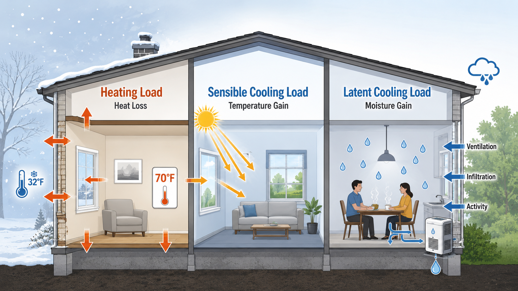
The calculation must separate the type of load because each result controls a different equipment or air-distribution decision.
Heating load
Heating load is the rate at which heat must be added to maintain the indoor heating setpoint at the selected winter design condition. Major contributors include transmission through exterior assemblies, infiltration, ventilation, ducts outside the conditioned envelope, and other project-specific losses.
Sensible cooling load
Sensible cooling load is the heat that raises dry-bulb temperature. Envelope transmission, window solar gain, outdoor air, occupants, lighting, appliances, motors, computers, ducts, and fan heat can contribute.
Latent cooling load
Latent cooling load represents moisture removal. Outdoor air, infiltration, occupants, cooking, washing, plants, and processes can add water vapor. A unit with sufficient total capacity may still be a poor match when its sensible and latent capacity split does not match the building.
Total cooling load and sensible heat ratio
Total cooling load is the sum of sensible and latent cooling. Sensible heat ratio is the sensible portion divided by the total. The ratio helps describe the required balance between temperature reduction and moisture removal.
ACCA Manual J identifies separate heating, sensible cooling, latent cooling, room, zone, and block load procedures for residential buildings within its scope: Manual J Residential Load Calculation.
Where HVAC Heating and Cooling Loads Come From
A complete load is the sum of individual heat and moisture paths, calculated for the room where each path occurs.

Walls, roofs, floors, ceilings, and doors
Heat transfer depends on assembly area, complete assembly U-value, adjacent condition, indoor and outdoor temperatures, and the procedure used to account for thermal response. Framing and thermal bridges mean that insulation R-value alone is not the whole-assembly performance.
Windows, skylights, and solar exposure
Fenestration contributes conduction and solar heat gain. Orientation, glass area, U-factor, solar heat gain coefficient, exterior shading, interior shading, tilt, frame, and time of day can make otherwise similar rooms peak at different times.
Infiltration, ventilation, exhaust, and makeup air
Outdoor air can add heating, sensible cooling, and latent cooling load. Infiltration is uncontrolled leakage. Ventilation is intentional outdoor air. Exhaust may require conditioned makeup air. These air quantities must be entered consistently so they are not omitted or double counted.
People, lighting, appliances, and equipment
Occupants can add sensible and latent heat. Lighting normally adds sensible heat. Appliances, computers, motors, cooking, and processes may add sensible heat, latent heat, or both, and schedules determine whether those gains coincide with the building peak.
Ducts, leakage, and fan heat
Ducts outside the conditioned envelope can gain or lose heat. Leakage changes the amount of conditioned air delivered and may draw outdoor or unconditioned air into the system. Fan energy can also become a cooling load.
HVAC Load Calculation Input Checklist
Accurate arithmetic cannot correct inaccurate building inputs. Collect and verify the following information before calculating the load.
Winter design temperature, summer dry-bulb and moisture conditions, indoor setpoints, humidity target, elevation, and operating schedules.
Room dimensions, orientation, exterior surfaces, adjacent conditions, construction assemblies, windows, doors, skylights, shading, and leakage.
Ventilation, infiltration, exhaust, makeup air, occupants, lighting, equipment, processes, ducts, fan heat, and control zones.
Design weather and indoor conditions
- Winter outdoor design dry-bulb temperature
- Summer outdoor dry-bulb and moisture condition
- Indoor heating and cooling setpoints
- Indoor humidity or dew-point target when required
- Site elevation and applicable air-density correction
- Occupied, unoccupied, and process schedules
Room geometry, orientation, and adjacency
- Room dimensions, floor area, and ceiling height
- Exterior wall, roof, floor, ceiling, door, window, and skylight areas
- North, east, south, and west orientation
- Adjacency to outdoors, ground, attics, crawlspaces, garages, or unconditioned rooms
- Permanent shading and neighboring obstructions
Envelope and fenestration properties
- Whole-assembly U-values or verified construction descriptions
- Window and skylight U-factor and solar heat gain coefficient
- Frame, glass, coatings, screens, shading, and skylight tilt where applicable
- Insulation condition, continuity, and thermal bridges
- Measured or procedurally estimated leakage and infiltration
Outdoor air, internal gains, ducts, and fans
- Ventilation, exhaust, and makeup-air quantities
- Occupant count and activity
- Lighting and equipment power with schedules
- Cooking, laundry, process, and moisture-producing activities
- Duct location, surface area, insulation, leakage, and operating condition
- Fan power or fan heat where required by the calculation procedure
Core HVAC Load Formulas and What They Mean
These equations explain common load components and support preliminary checks. They do not reproduce the complete solar, thermal-mass, diversity, duct, ventilation, and documentation procedures in Manual J or Manual N.
Envelope transmission load
Use consistent units. In U.S. customary units, Q̇ is in BTU/hr when U is in BTU/(hr·ft²·°F), area is in ft², and temperature difference is in °F.
Sensible load from outdoor or infiltrating air
The factor 1.08 is an approximate standard-air value. Elevation, density, and reference conditions can change the appropriate factor.
Latent load from outdoor air
The moisture difference must use compatible psychrometric data in grains of moisture per pound of dry air. The coefficient is an approximation tied to reference air conditions.
Total cooling load
Sensible heat ratio
Preliminary room airflow from sensible load
This is a starting airflow relationship. Final airflow depends on equipment sensible capacity, humidity control, ventilation, air distribution, acoustics, fan selection, and duct design.
Cooling-load conversion to refrigeration tons
A calculated load of 2.92 tons does not automatically mean “install a 3-ton unit.” Equipment must be matched to heating, sensible, latent, and total loads using manufacturer performance at the design conditions.
Manual J, Manual N, Room Loads, and Block Loads
The correct load procedure depends on the building type, and room-by-room and whole-building results answer different design questions.
| Procedure | Application | Primary outputs | What follows |
|---|---|---|---|
| ACCA Manual J | Residential buildings and dwelling units within the procedure’s scope | Heating, sensible cooling, latent cooling, room, zone, and block equipment-sizing loads | Manual S equipment selection and Manual D duct design |
| ACCA Manual N | Commercial buildings and commercial spaces within the procedure’s scope | Heating and cooling loads with commercial schedules, internal gains, ventilation, zoning, and diversity considerations | Commercial equipment, airflow, zoning, hydronic, and air-distribution design |
Room-by-room load
Room loads identify where heating and cooling are required. They support airflow allocation, branch ducts, supply outlets, return-air strategy, zoning, terminal selection, and comfort analysis.
Zone load
A zone load combines rooms served by one control zone or system while accounting for the calculation procedure’s timing and diversity rules. Rooms should not be grouped merely because they are adjacent.
Whole-building or block load
The block load is the coincident requirement for the system or building. It supports equipment selection but does not show how capacity must be distributed to each room.
Do not simply add every room’s independent maximum. East- and west-facing rooms, internal gains, schedules, and ventilation may peak at different times.
ACCA states that Manual J 8th Edition is the ANSI-recognized residential procedure and includes component, room, zone, block, infiltration, ventilation, duct, internal, and moisture-related load procedures: Manual J.
Step-by-Step HVAC Load Calculation Workflow
The load calculation should progress from verified building inputs to room loads, coincident system loads, equipment selection, airflow, and distribution design.

- Select design conditions. Establish representative outdoor winter and summer conditions and indoor temperature and humidity targets.
- Create rooms and zones. Separate spaces with different orientations, exposures, schedules, uses, or controls.
- Build the geometry. Enter room dimensions, exposed surfaces, orientations, adjacent conditions, windows, doors, skylights, and shading.
- Assign thermal properties. Use complete assembly and fenestration properties rather than generic insulation assumptions.
- Calculate envelope and solar loads. Evaluate opaque surfaces, fenestration conduction, and solar exposure according to the applicable method.
- Calculate outdoor-air loads. Add infiltration, ventilation, exhaust makeup air, sensible load, and latent load consistently.
- Add internal gains. Include occupants, lighting, equipment, cooking, motors, and process loads with realistic schedules.
- Add duct and fan effects. Include applicable heat transfer, leakage, and fan heat without double counting.
- Review room results. Check heating, sensible cooling, latent cooling, and the largest contributors for each room.
- Develop zone and block loads. Apply the procedure’s timing, diversity, and system-grouping rules.
- Select equipment. Compare the loads with manufacturer heating, sensible, latent, and total performance at design conditions.
- Design airflow and distribution. Use room loads, selected equipment, required airflow, duct geometry, terminals, and pressure relationships.
Sort the report by largest load component. An unexpectedly large wall, window, ventilation, infiltration, duct, or internal load often reveals an incorrect area, orientation, U-value, airflow, unit conversion, or duplicate input.
Complete Simplified HVAC Load Calculation Example
Calculate Sensible Load, Latent Load, Total Load, SHR, Airflow, and Tons
This educational example demonstrates the result chain readers most often need to understand. The assumed component values stand in for detailed Manual J or Manual N calculations.
A formal load calculation uses more detailed methods for weather, solar gain, thermal response, infiltration, ventilation, ducts, diversity, schedules, and documentation.
Add the Sensible Cooling Loads
Combine only the temperature-related loads before calculating airflow or SHR.
Add the Latent Cooling Loads
Combine moisture-related loads separately from sensible heat.
Calculate Total Cooling Load
Add sensible and latent loads to determine the total cooling requirement.
Calculate Sensible Heat Ratio
Determine what portion of the total cooling load is temperature-related.
Estimate Preliminary Room Airflow
Use sensible load and the assumed supply-to-room temperature difference to estimate starting airflow.
Convert Total Load to Refrigeration Tons
Express the load in familiar units without treating the result as a final equipment selection.
11,760 BTU/hr divided by 544 CFM is approximately 21.6 BTU/hr per CFM, which matches 1.08 × 20°F.
The example starts with assumed component loads and does not reproduce full Manual J or Manual N solar, thermal-response, duct, infiltration, diversity, and documentation procedures.
Combine room loads according to the applicable procedure, select equipment from actual performance data, and design the airflow and duct system.
How Load Results Control Equipment, Airflow, and Duct Design
Each result should flow into a specific downstream design decision rather than being collapsed into one tonnage number.
Heating load
Compare the heating load with equipment output at the winter design condition. Heat-pump capacity can change significantly with outdoor temperature, so nominal size or warm-weather capacity is not sufficient.
Room sensible load
Use room sensible load to develop preliminary room airflow and evaluate supply-air distribution. Do not allocate airflow only by room floor area.
Latent load
Use latent load to evaluate moisture-removal capability. A cooling unit can meet total load and still provide an unsuitable sensible-to-latent capacity split.
Zone and block load
Use coincident zone or block load to evaluate system capacity. The selected grouping must reflect controls, schedules, exposures, equipment arrangement, and the applicable procedure.
Residential Manual J, S, and D sequence
- Manual J: Calculate room, zone, and block heating and cooling loads.
- Manual S: Match equipment to the loads using manufacturer performance at design conditions.
- Manual D: Design ducts using selected equipment airflow, fan capability, layout, fittings, materials, and pressure relationships.
ACCA’s residential review guidance separates load calculation, equipment selection, and duct design into Manual J, Manual S, and Manual D rather than treating them as one calculation: Residential System Design Review Forms and Examples.
How to Review an HVAC Load Calculation Report
A useful report should make the inputs, results, assumptions, and downstream design decisions auditable.
- Weather: Location, winter and summer design conditions, indoor setpoints, humidity assumptions, and elevation are identified.
- Geometry: Room dimensions, surface areas, orientation, adjacency, windows, doors, skylights, and shading match the building.
- Envelope: Complete assembly and fenestration properties are traceable to plans, labels, specifications, inspection, or stated assumptions.
- Air leakage: Infiltration method, leakage input, blower-door data where used, and treatment of ventilation and exhaust are documented.
- Internal gains: Occupants, lighting, equipment, appliances, processes, and schedules are realistic and not duplicated.
- Ducts and fans: Duct location, insulation, leakage, surface area, and fan heat are included according to the procedure.
- Room results: Heating, sensible cooling, latent cooling, and airflow are available by room where distribution design requires them.
- Peak timing: Zone and block results follow the applicable coincidence or diversity method rather than adding every independent room peak.
- Largest components: Unusually large windows, ventilation, infiltration, ducts, walls, or internal loads have been investigated.
- Equipment separation: The report does not imply that calculated tons equal selected nominal equipment size.
- Software: Formal ACCA-compliant work uses software recognized for the applicable procedure.
- Documentation: Assumptions, defaults, overrides, exclusions, and revision dates are visible.
Common Load Calculation Mistakes and When to Use a Professional
The largest errors usually come from shortcuts, default inputs, double counting, or confusing the load calculation with equipment selection.
- Using BTU per square foot: Floor area does not capture weather, glass, orientation, insulation, leakage, ventilation, moisture, ducts, or internal gains.
- Using the wrong design weather: An unrepresentative city or mixed weather dataset can distort heating and cooling loads.
- Ignoring orientation and shading: Solar loads and peak timing can vary greatly by room.
- Using insulation R-value as the assembly: Framing and thermal bridges change the whole-assembly U-value.
- Guessing window properties: U-factor, solar heat gain coefficient, frame, glass, coatings, and shading materially affect cooling load.
- Ignoring latent load: Sensible BTU/hr does not represent the complete cooling requirement.
- Double counting outdoor air: Infiltration, ventilation, exhaust makeup air, and duct leakage must be treated consistently.
- Adding arbitrary safety factors: Conservative inputs and extra margins can compound into substantial oversizing.
- Adding every room peak: Independent room maximums may occur at different times.
- Selecting from nominal tons: Manufacturer heating, sensible, latent, and total capacity must be evaluated at design conditions.
Use a preliminary calculator for
- Learning how building inputs affect heating and cooling load
- Comparing insulation, window, leakage, or setpoint scenarios
- Early planning, budgeting, and reasonableness checks
- Identifying questions to resolve before formal design
Use approved software or a qualified professional for
- New HVAC equipment selection or replacement sizing
- Permit, code, rebate, or incentive documentation
- Room-by-room airflow, zoning, outlet, and duct design
- Heat-pump selection at project heating and cooling conditions
- Major additions, envelope changes, or system conversions
- Persistent comfort, humidity, noise, or airflow problems
- Commercial ventilation, schedules, diversity, fan heat, and process loads
The Turn2Engineering HVAC Load Calculator supports education and preliminary estimates. Formal ACCA-compliant documentation requires the applicable procedure and recognized software.
ACCA states that software not listed on its approved-software page is not ACCA-approved for producing compliant results: ACCA Approved Software.
HVAC Load Calculation Engineering References
These sources support the calculation scope, residential and commercial procedures, software requirements, design sequence, and risks of rule-of-thumb equipment sizing.
- Air Conditioning Contractors of America — Manual J Residential Load Calculation ANSI/ACCA 2 Manual J—2016. Residential component, room, zone, block, heating, sensible cooling, latent cooling, infiltration, ventilation, duct, internal, and moisture-related load procedures.
- Air Conditioning Contractors of America — Manual N Commercial Load Calculation Commercial heating and cooling load procedures, including room, zone, block, ventilation, internal, fan, duct, schedule, and diversity considerations.
- Air Conditioning Contractors of America — Approved Software Current software recognized by ACCA for applicable Manual J, Manual D, and Manual N procedures.
- U.S. Department of Energy — Proper HVAC Sizing of HVAC Systems Explains why heating and cooling loads should be calculated before equipment selection and why rules of thumb can produce oversized systems.
- ACCA — Residential System Design Review Forms and Examples Summarizes the relationship among Manual J load calculation, Manual S equipment selection, and Manual D duct design.
Frequently Asked Questions
How do I calculate HVAC load?
Calculate envelope, solar, outdoor-air, infiltration, occupant, lighting, equipment, moisture, duct, and fan loads for each room at selected design conditions. Combine them into heating, sensible cooling, latent cooling, room, zone, and coincident building loads according to the applicable procedure.
How many BTU per square foot do I need?
No single BTU-per-square-foot value is reliable for final equipment sizing. Equal-size buildings can have different loads because of weather, windows, orientation, shading, insulation, leakage, ventilation, occupancy, moisture, ducts, and internal equipment.
How do I convert HVAC load to tons?
Divide total cooling load in BTU/hr by 12,000 to express the load in refrigeration tons. This is a unit conversion only; equipment selection must use actual manufacturer performance at the design conditions.
Why is room-by-room load calculation important?
Room loads show where heating and cooling are required. They support room airflow, supply outlets, return-air strategy, branch ducts, zoning, and comfort analysis that a whole-building load cannot provide.
What is the difference between HVAC load and equipment capacity?
Load is what the building requires at the selected design condition. Capacity is what a specific unit can deliver at stated indoor, outdoor, airflow, and configuration conditions. Equipment should be selected by comparing both sets of values.
Summary and Next Step
An HVAC load calculation builds heating, sensible cooling, latent cooling, room, zone, and building requirements from verified weather, geometry, envelope, fenestration, outdoor-air, internal-gain, duct, fan, and schedule inputs.
Use simplified equations to understand and check individual components. Use the applicable full procedure and recognized software when selecting equipment, designing airflow, or producing formal documentation.