
Table of Contents
Direct Answer
The major HVAC system families are ducted split systems, packaged unitary systems, ductless mini-splits, heat-pump systems, variable refrigerant flow systems, central all-air systems, hydronic systems, air-water systems, radiant systems, water-source heat-pump systems, and central heating-and-cooling plants. The categories overlap because some terms describe equipment arrangement, others describe the energy-delivery medium, and others describe controls or heat-production technology.
The most useful comparison is not “which system is best?” but “which complete system can meet the building loads, outdoor-air, humidity, zoning, space, controls, maintenance, resilience, and lifecycle requirements?”
Key Selection Principles
- Classify the whole system: Distinguish equipment arrangement, delivery medium, heat source, ventilation, and zone control.
- Separate ventilation from heating and cooling: A system that conditions a zone does not automatically provide required outdoor air.
- Eliminate infeasible options first: Loads, shafts, ceiling space, utilities, roof loading, acoustics, access, and owner capability create hard constraints.
- Compare real operating conditions: Part-load performance, humidity control, fan and pump energy, maintenance, and controls often matter more than one rated efficiency value.
- Verify the complete path: A viable system must produce heating or cooling, distribute it, ventilate the spaces, control zones, reject heat where required, and remain serviceable.
HVAC System Types at a Glance
Use this first-pass comparison to understand the major system arrangements before evaluating detailed design criteria.
| System family | Primary delivery | Common fit | Major strength | Main issue to verify |
|---|---|---|---|---|
| Ducted split system | Refrigerant and air | Homes and light commercial | Familiar equipment and whole-building air distribution | Duct condition, return paths, ventilation, humidity, and equipment sizing |
| Packaged rooftop unit | Air | Retail, restaurants, offices, and low-rise commercial | Factory package with limited indoor equipment space | Roof loading, weather exposure, access, zoning, and duct routing |
| Ductless mini-split | Refrigerant | Additions, retrofits, and individual zones | Minimal ductwork and strong local control | Outdoor air, condensate, appearance, capacity diversity, and service access |
| Variable refrigerant flow | Refrigerant | Multizone offices, hotels, multifamily, and retrofits | Extensive zoning with reduced large-duct demand | Ventilation, refrigerant limits, controls, piping, and technician capability |
| Central all-air | Air | Large commercial and institutional buildings | Centralized ventilation, filtration, humidity, and pressure control | Duct and shaft space, fan energy, terminal control, balancing, and commissioning |
| Fan-coil or water-source terminal system | Water or water loop plus local air | Hotels, offices, multifamily, and campuses | Compact distribution and local zone control | Outdoor air, condensate, distributed maintenance, valves, filters, and controls |
| Radiant plus ventilation air | Water and air | Comfort-focused and high-performance buildings | Low air-distribution demand and quiet sensible conditioning | Condensation, surface capacity, response time, envelope, and ventilation |
| Central plant with air handlers | Water and air | Large buildings, campuses, healthcare, and high-load facilities | Plant staging, diversity, redundancy, and centralized service | First cost, plant space, controls, distribution, operators, and lifecycle value |
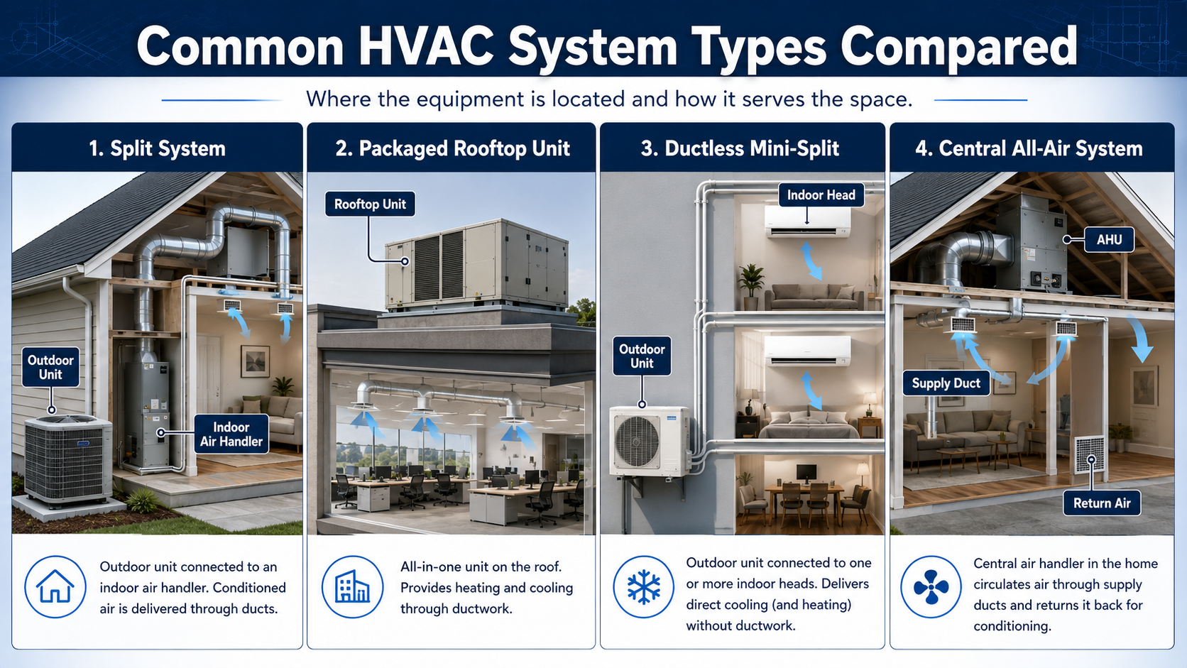
The table identifies system families worth investigating. It does not replace load calculations, ventilation design, equipment performance checks, energy modeling, acoustic analysis, or lifecycle comparison.
A Better Way to Classify HVAC Systems
HVAC terminology becomes much clearer when every term is assigned to the part of the system it actually describes.
Equipment arrangement
Examples: split, packaged, rooftop, central, decentralized, and terminal. These terms describe where major equipment is located and how it is grouped.
Energy-delivery medium
Examples: all-air, hydronic, refrigerant, and air-water. These terms describe what moves heating or cooling through the building.
Heating or cooling technology
Examples: furnace, boiler, heat pump, chiller, evaporative cooling, and electric resistance. These terms describe how thermal energy is produced or transferred.
Zone-control method
Examples: constant air volume, variable air volume, single-zone, multizone, and variable refrigerant flow. These terms describe how output changes with zone demand.
Ventilation strategy
Examples: integrated outdoor air, dedicated outdoor air, natural ventilation, makeup air, and local exhaust. These terms describe how outdoor air and exhaust are handled.
Zone terminal
Examples: diffuser, VAV box, fan coil, chilled beam, radiator, radiant panel, indoor VRF unit, and water-source heat pump.
A heat pump, boiler, chiller, VAV box, or DOAS is not automatically a complete HVAC system. A complete comparison must trace energy production, distribution, ventilation, zone control, condensate, heat rejection, and maintenance.
The 2024 ASHRAE Handbook—HVAC Systems and Equipment separates system analysis, decentralized systems, central plants, air distribution, terminal systems, radiant systems, heat pumps, hydronic systems, VRF, unitary equipment, and dedicated outdoor-air systems into distinct technical topics.
How HVAC Systems Deliver Heating and Cooling
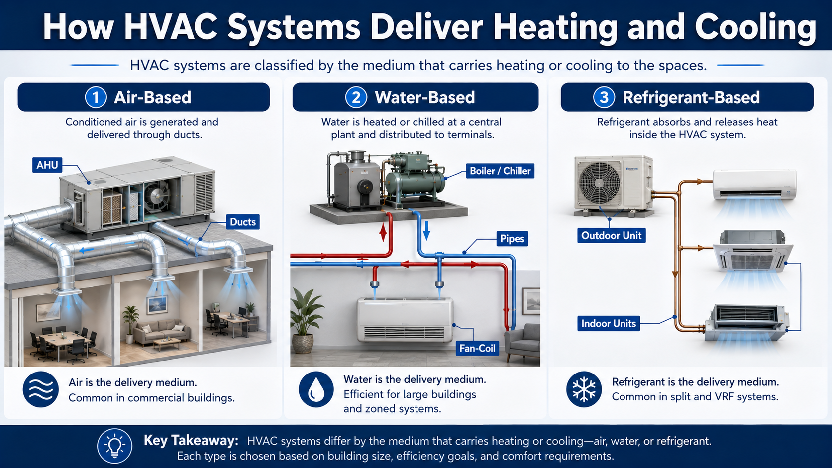
The delivery medium strongly affects shaft size, ceiling coordination, pumping or fan energy, zoning, ventilation integration, and maintenance location.
All-air systems
All-air systems use ductwork to deliver heating, cooling, ventilation, filtration, and humidity control. Central air handlers and packaged units can coordinate multiple indoor-air functions, but large ducts, fan pressure, shaft space, balancing, leakage, and terminal noise must be addressed.
Hydronic systems
Hydronic systems circulate heated or chilled water to air-handler coils, fan coils, radiant terminals, chilled beams, radiators, or process equipment. Piping can transport thermal energy through less building volume than low-pressure ductwork, but occupied spaces still require an outdoor-air and exhaust strategy.
Direct-refrigerant systems
Split systems, mini-splits, packaged DX equipment, and VRF systems circulate refrigerant between heat-rejection equipment and indoor coils. These systems can reduce central plant and large-duct requirements, but refrigerant piping, code limits, condensate, service expertise, and ventilation remain project constraints.
Air-water systems
Air-water systems often use primary air for outdoor-air ventilation and humidity control while water-based terminals handle much of the zone sensible load. The arrangement can reduce primary duct size, but the air and water systems must be designed as one coordinated sequence.
Common Residential and Light-Commercial HVAC Systems
Residential and small-building systems are usually unitary or decentralized, but the correct choice still depends on loads, climate, ducts, ventilation, humidity, utilities, and zoning.
Ducted split system
A conventional split system places a condenser or heat-pump unit outdoors and a furnace, air handler, or evaporator coil indoors. Ductwork distributes supply air and returns air to the equipment. The arrangement is common because equipment and service practices are familiar, but performance depends heavily on load-based sizing and duct quality.
Best fit: Whole-home conditioning where usable ducts or adequate duct pathways exist. Disqualifying concerns: severely constrained duct space, inaccessible return paths, major leakage, or a renovation where duct replacement is impractical.
Air-source heat pump and dual-fuel
A heat pump reverses its refrigeration cycle to provide cooling and heating. It may be ducted, ductless, packaged, water-source, or ground-source. A dual-fuel arrangement combines a heat pump with another heat source and changes operating mode according to capacity, temperature, cost, or control logic.
Verify: Heating capacity at the project design temperature, defrost, supplemental heat, electrical service, sound, refrigerant, controls, and the selected distribution system.
Ductless mini-split
A ductless mini-split connects outdoor equipment to one or more local indoor units. It is useful for additions, retrofits, isolated rooms, and buildings without practical duct routes. It provides local heating and cooling but should not be assumed to provide code-required outdoor air.
Packaged and rooftop systems
A packaged system places major heating, cooling, fan, filtration, and control components in one cabinet. Residential packaged units may be located outdoors at grade or on a roof; commercial rooftop units connect to supply and return ducts below. Package construction saves indoor equipment space but increases weather, roof, access, and curb coordination.
Ground- and water-source heat pumps
Water-source and ground-source heat pumps exchange heat with a water loop, groundwater source, or ground heat exchanger. They can provide efficient zone-level heating and cooling, but pumping, loop design, drilling or water access, water quality, controls, first cost, and regulatory constraints must be evaluated.
Commercial and Large-Building HVAC System Families
Larger buildings require system architectures that coordinate many zones, outdoor air, humidity, operating schedules, pressure relationships, controls, maintenance, and redundancy.
Central all-air CAV and VAV
A central all-air system conditions air at one or more air-handling units and distributes it through ducts. Constant-air-volume systems maintain relatively constant airflow, while variable-air-volume systems reduce or increase zone airflow as loads change. VAV can reduce fan energy and serve many zones, but minimum airflow, reheat, ventilation, static-pressure reset, sensors, terminal controls, balancing, and commissioning determine real performance.
Variable refrigerant flow
VRF systems connect multiple indoor units to shared outdoor equipment and vary refrigerant flow with zone demand. They offer flexible zoning and can reduce large ductwork, but ventilation is commonly handled separately. Refrigerant concentration limits, piping restrictions, controls, branch components, failure impact, condensate, acoustics, and qualified service capability are critical.
Fan-coil units with dedicated outdoor air
Fan coils use local fans and water coils to condition individual zones. A dedicated outdoor-air system can deliver dehumidified ventilation air while the fan coils handle local sensible loads. This reduces large supply ducts but distributes filters, valves, motors, condensate systems, and maintenance points throughout the building.
Radiant systems and chilled beams
Radiant floors, ceilings, and panels condition spaces through surface heat exchange. Chilled beams combine water-side sensible cooling with room-air induction or primary ventilation air. These systems can improve comfort and reduce fan demand, but condensation control, envelope quality, ventilation, dew-point control, response time, and surface capacity must be demonstrated.
Central chilled-water and heating plants
Central plants produce heating or cooling at shared equipment and distribute water or steam to air handlers and terminals. They can support staging, diversity, heat recovery, redundancy, district connections, and centralized maintenance. The benefits must justify plant rooms, pumps, towers or other heat rejection, controls, operators, water treatment, replacement access, and capital cost.
What Actually Determines the Best HVAC System
The best system is the feasible option that most completely satisfies the project requirements over its expected service life.
Loads and climate
Heating, sensible cooling, latent cooling, outdoor-air, infiltration, solar, occupancy, schedule, process, and design-weather conditions establish capacity and moisture-control requirements.
Zoning and schedules
Perimeter exposure, occupancy, tenant hours, equipment loads, room use, and simultaneous heating and cooling determine the required zone granularity.
Space and structure
Ceiling depth, shafts, plant rooms, roof loading, clearances, replacement routes, structural openings, piping, ducts, and architectural impacts eliminate otherwise attractive options.
Indoor environmental requirements
Temperature, humidity, ventilation, filtration, acoustics, pressure relationships, contaminants, exhaust, and process conditions define what the system must control.
Utilities and energy
Electrical capacity, fuels, water, demand charges, climate, heat recovery, electrification goals, grid constraints, emissions, and local rates change comparative performance.
Operations and maintenance
Staff capability, access, equipment count, filter locations, alarms, replacement parts, controls support, redundancy, and acceptable downtime determine long-term viability.
- Required heating, sensible, latent, ventilation, exhaust, and pressurization performance
- Feasible central, distributed, and hybrid system architectures
- Space, structural, electrical, fuel, water, noise, and access constraints
- Controls, commissioning, maintenance, resilience, and replacement strategy
- First cost, modeled annual energy, lifecycle cost, and owner priorities
The U.S. Department of Energy explains that HVAC configuration, zoning, sizing, hydronic and air distribution, heat sources, controls, and hybridization can be compared through building-energy modeling: Building Energy Modeling 101: HVAC Design and Operation Use Case.
How Engineers Choose an HVAC System Type
Use this workflow to eliminate systems that cannot satisfy the project before spending time on detailed equipment selection.
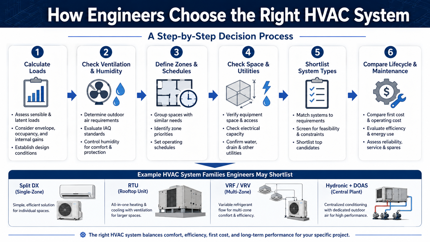
- Calculate the loads. Establish heating, sensible cooling, latent cooling, ventilation, infiltration, occupancy, lighting, equipment, and schedule-related loads.
- Define indoor-environment requirements. Document temperatures, humidity, filtration, outdoor air, exhaust, pressure relationships, acoustics, and special process needs.
- Map zones and schedules. Group spaces with compatible loads, exposures, occupancy, use, and operating hours.
- Document hard constraints. Confirm shafts, ceiling depth, plant space, roof loading, access, utilities, drainage, structure, phasing, and architectural limits.
- Choose feasible architectures. Compare central, decentralized, and hybrid systems; eliminate arrangements that cannot physically or operationally work.
- Choose feasible delivery media. Compare air, water, refrigerant, and air-water distribution for the remaining architectures.
- Define ventilation independently. Trace outdoor air, exhaust, filtration, humidity control, and building pressure under occupied and unoccupied modes.
- Check controls and maintenance. Review equipment count, service locations, staffing, sequences, alarms, interoperability, spare parts, and replacement access.
- Model the finalists. Compare loads, equipment performance, fan and pump energy, part-load operation, heat recovery, controls, and utility impacts.
- Document the basis of design. Record why the selected system satisfies the project and why the rejected alternatives were eliminated.
A final recommendation should state the assumptions, required performance, eliminated options, remaining risks, owner responsibilities, and verification required during design, construction, and commissioning.
Worked HVAC System Shortlisting Example
Consider a multizone office renovation with different tenant schedules, limited ceiling depth, required outdoor air, restricted roof loading, and a requirement to keep much of the building occupied during construction.
- Define the controlling constraints: Limited ceiling depth restricts large supply and return ducts; roof loading restricts large rooftop equipment; occupied phasing limits demolition and shutdowns.
- Evaluate central all-air: A new VAV system can integrate ventilation and humidity control, but large duct routes and shafts may make it infeasible without major construction.
- Evaluate multiple rooftop units: Packaged units can divide the building into zones, but structural loading, curb work, roof access, noise, and occupied tie-ins may eliminate the option.
- Evaluate VRF plus outdoor air: Refrigerant distribution can fit the ceiling constraints and support tenant zoning, but a separate ventilation strategy, refrigerant-limit review, controls, and service capability are mandatory.
- Evaluate fan coils plus DOAS: Water piping and smaller ventilation ducts can fit constrained areas, but distributed filters, valves, drains, and maintenance access must be acceptable.
- Shortlist the feasible systems: Retain VRF plus DOAS and fan coils plus DOAS for detailed load, humidity, acoustic, energy, first-cost, maintenance, controls, and lifecycle comparison.
The example does not identify a universal winner. A real project requires verified loads, ventilation, refrigerant and code analysis, equipment selections, piping and duct layouts, energy modeling, cost estimates, and owner review.
HVAC System Types by Building Application
Building type narrows the candidate systems, but it does not determine the answer without project-specific analysis.
Single-family home
Often considered: ducted heat pump, furnace with cooling, dual-fuel, ductless, or ground-source. Focus: climate, ducts, humidity, comfort, electrical capacity, sound, and installation cost.
Retail or restaurant
Often considered: rooftop units, split systems, DOAS, and dedicated kitchen systems. Focus: occupancy, outdoor air, exhaust, makeup air, roof access, zoning, and schedules.
Office
Often considered: VAV, VRF plus outdoor air, fan coils plus DOAS, heat pumps, or packaged systems. Focus: perimeter and interior loads, tenant schedules, zoning, controls, and flexibility.
Hotel or multifamily
Often considered: fan coils, water-source heat pumps, VRF, packaged terminals, or central hydronic systems. Focus: room control, acoustics, ventilation, condensate, distributed service, and metering.
School
Often considered: VAV, packaged systems, heat pumps, fan coils plus DOAS, or central hydronic systems. Focus: outdoor air, filtration, acoustics, variable occupancy, maintainability, and lifecycle cost.
Healthcare
Often considered: central all-air systems, central plants, hydronic systems, and specialized air systems. Focus: pressure relationships, filtration, humidity, redundancy, infection-control requirements, and commissioning.
Warehouse or industrial
Often considered: packaged units, unit heaters, radiant systems, makeup-air systems, evaporative cooling where suitable, or process-specific HVAC. Focus: door infiltration, stratification, exhaust, process loads, and high ceilings.
Campus or district
Often considered: central chilled-water and heating plants, district energy, distributed heat pumps, or hybrid plants. Focus: diversity, redundancy, distribution losses, expansion, operators, and long-term capital planning.
Retrofit or addition
Often considered: ductless, small ducted heat pumps, VRF, fan coils, or extensions of existing systems. Focus: existing capacity, phasing, access, disruption, envelope, controls integration, and outdoor air.
Where HVAC System Choices Fail in Practice
Most system-selection failures begin with an incomplete design basis rather than an inherently bad equipment type.
- Selecting before calculating loads: This can produce oversizing, cycling, poor humidity control, insufficient capacity, or unnecessary infrastructure.
- Assuming heating and cooling equipment provides ventilation: Local indoor units and zone terminals may recirculate room air without delivering outdoor air.
- Ignoring latent load and dew point: A system can maintain temperature while allowing high humidity, condensation, discomfort, and moisture risk.
- Creating too few control zones: Spaces with different orientation, schedules, occupancy, or internal loads can overheat and overcool simultaneously.
- Underestimating distribution space: Ducts, pipes, refrigerant lines, drains, insulation, valves, dampers, access, and structure compete for the same space.
- Comparing only rated equipment efficiency: Fan energy, pump energy, distribution losses, reheat, simultaneous heating and cooling, cycling, controls, and schedules determine building performance.
- Choosing controls beyond operator capability: Unsupported sequences, poor trending, overrides, unresolved alarms, and sensor failures can erase expected benefits.
- Ignoring maintenance location and quantity: Hundreds of distributed filters, valves, drains, motors, or fan coils can impose a very different burden than centralized equipment.
- Omitting resilience requirements: Shared refrigerant circuits, central plants, common fans, and single electrical feeds create different failure consequences.
- Skipping commissioning: Incorrect setpoints, airflow, water flow, ventilation, static pressure, sensor calibration, and schedules can prevent the selected architecture from working as intended.
A system type should be judged by installed and operated performance—not by the best-case catalog condition. Maintainability, accessibility, controls, balancing, training, and verification are part of the engineering selection.
HVAC System Selection QA/QC Checklist
Use this checklist before accepting a preferred system or issuing a basis of design.
- Loads: Heating, sensible, latent, ventilation, exhaust, infiltration, process, and schedule loads are documented.
- Zones: Orientation, occupancy, operating hours, room use, internal loads, and control expectations support the zoning plan.
- Outdoor air: The path from intake through conditioning and distribution to every occupied zone is defined.
- Humidity: Moisture removal, dew-point control, condensate, reheat where applicable, and part-load behavior are addressed.
- Physical fit: Equipment, ducts, pipes, refrigerant lines, drains, insulation, valves, dampers, access, and replacement routes are coordinated.
- Utilities: Electrical, fuel, water, drainage, heat rejection, structural support, and emergency-power requirements are confirmed.
- Controls: Sequences, sensors, setpoints, alarms, integration, trending, cybersecurity, and operator capability are defined.
- Acoustics: Equipment, terminals, ducts, piping, structure-borne transmission, exterior sound, and sensitive spaces are reviewed.
- Maintenance: Service access, filter replacement, cleaning, water treatment, condensate, spare parts, staffing, and shutdowns are acceptable.
- Resilience: Failure domains, redundancy, standby capacity, partial operation, and acceptable downtime are documented.
- Energy and lifecycle: Part-load operation, fan and pump energy, heat recovery, controls, utility rates, maintenance, replacement, and first cost are compared.
- Codes and standards: Applicable mechanical, energy, ventilation, refrigerant, fire, smoke, health, and jurisdictional requirements are verified.
- Commissioning: Required functional tests, measurements, balancing, seasonal checks, trend reviews, and acceptance criteria are identified.
- Decision record: The selected system, rejected alternatives, assumptions, risks, and owner responsibilities are documented.
HVAC System Classification and Selection References
These sources support the system-family framework and the process of comparing equipment arrangements, delivery media, zoning, ventilation, controls, and building-level performance.
- ASHRAE — 2024 Handbook, HVAC Systems and Equipment Official table of contents covering system analysis and selection, decentralized systems, central plants, air distribution, terminal systems, radiant systems, heat pumps, hydronic systems, VRF, unitary systems, and dedicated outdoor-air systems.
- ASHRAE — Description of the 2024 HVAC Systems and Equipment Handbook Explains that the handbook compares system and equipment features to support selection and use by designers and operators.
- U.S. Department of Energy — Building Energy Modeling for HVAC Design and Operation Supports project-specific comparison of HVAC configuration, zoning, sizing, air and hydronic distribution, controls, and hybrid strategies.
- ASHRAE — 2025 Handbook, Fundamentals Supports load, psychrometric, heat-transfer, duct, piping, indoor-environment, and other foundational calculations required before system selection.
Frequently Asked Questions
How many types of HVAC systems are there?
There is no universal fixed number because HVAC systems can be classified by equipment arrangement, delivery medium, heating and cooling technology, ventilation strategy, terminal type, or control method. The practical families on this page cover the arrangements most commonly compared for residential and commercial buildings.
What are the four basic residential HVAC system types?
A simplified residential list commonly includes split heating-and-cooling systems, heat-pump systems, ductless mini-splits, and packaged systems. That list is useful for homeowners but does not cover all commercial, hydronic, radiant, central-plant, or air-water systems.
Is a heat pump a complete HVAC system type?
A heat pump describes reversible heating-and-cooling technology. It can be used in ducted split, ductless, packaged, VRF, water-source, ground-source, or central-plant arrangements, so the rest of the distribution and ventilation system must also be identified.
What is the difference between central and decentralized HVAC?
Central HVAC concentrates major heating, cooling, or air-handling equipment in shared locations and distributes air or water through the building. Decentralized HVAC places more equipment near individual zones, on roofs, beside the building, or throughout occupied floors.
Which HVAC system is the most efficient?
No system is universally most efficient. Comparative performance depends on climate, envelope, loads, ventilation, humidity, equipment selection, distribution losses, part-load operation, controls, schedules, utility source, installation quality, and maintenance.
Summary and Next Step
HVAC systems are best understood as complete architectures rather than flat lists of equipment names. Classify each alternative by arrangement, delivery medium, heat-production technology, ventilation, terminals, and controls.
Then eliminate infeasible options using loads, indoor-environment requirements, building space, utilities, maintenance, resilience, codes, lifecycle value, and commissioning requirements.